Multi-tool with bit slot
Levand , et al. Oc
U.S. patent number D864,693 [Application Number D/659,953] was granted by the patent office on 2019-10-29 for multi-tool with bit slot. This patent grant is currently assigned to THE SHERWIN WILLIAMS COMPANY. The grantee listed for this patent is THE SHERWIN-WILLIAMS COMPANY. Invention is credited to Randi Boss, Sharad Gaurav, Edward Ray Goodwin, Michael C. Lambertson, Jr., Victor J. Levand, Sarah Bridget Mulroy, Joshua R. Robertson.

| United States Patent | D864,693 |
| Levand , et al. | October 29, 2019 |
Multi-tool with bit slot
Claims
CLAIM The ornamental design for a multi-tool with bit slot, as shown and described.
| Inventors: | Levand; Victor J. (Lyndhurst, OH), Gaurav; Sharad (Lakewood, IN), Mulroy; Sarah Bridget (Rocky River, OH), Robertson; Joshua R. (North Ridgeville, OH), Goodwin; Edward Ray (Westlake, OH), Boss; Randi (Avon Lake, OH), Lambertson, Jr.; Michael C. (Aurora, OH) | ||||||||||
|---|---|---|---|---|---|---|---|---|---|---|---|
| Applicant: |
|
||||||||||
| Assignee: | THE SHERWIN WILLIAMS COMPANY
(Cleveland, OH) |
||||||||||
| Appl. No.: | D/659,953 | ||||||||||
| Filed: | August 14, 2018 |
Related U.S. Patent Documents
| Application Number | Filing Date | Patent Number | Issue Date | ||
|---|---|---|---|---|---|
| 29591135 | Jan 17, 2017 | D828740 | |||
| Current U.S. Class: | D8/107 |
| Current International Class: | 0805 |
| Field of Search: | ;D8/45,107,14,82,83 ;D4/138 ;D7/395 ;D32/46,49,52 |
References Cited [Referenced By]
U.S. Patent Documents
| 4620369 | November 1986 | Gercken |
| 5251352 | October 1993 | Cullison |
| 5546625 | August 1996 | Mealey |
| 5615445 | April 1997 | Kelsay |
| 5956799 | September 1999 | Panaccione |
| 6009581 | January 2000 | Davis |
| D420887 | February 2000 | Chen |
| 6131222 | October 2000 | Anderson |
| 6131290 | October 2000 | Chiou |
| 6182317 | February 2001 | Huang |
| D444692 | July 2001 | Marquardt |
| D446104 | August 2001 | Chen |
| D456236 | April 2002 | Norton |
| D462251 | September 2002 | Collins |
| D472125 | March 2003 | Hsu |
| 6530098 | March 2003 | Gringer |
| 6668751 | December 2003 | Henke |
| D487387 | March 2004 | Chen |
| D498124 | November 2004 | Mitchell |
| D534781 | January 2007 | Chen |
| D535174 | January 2007 | Chen |
| D535541 | January 2007 | Holby |
| D569215 | May 2008 | Chiu |
| 7434318 | October 2008 | Perez |
| 7587778 | September 2009 | Rosso |
| D608177 | January 2010 | Perlman |
| D612702 | March 2010 | Perlman |
| D629578 | December 2010 | Molina |
| 8205341 | June 2012 | Rosso |
| 8844087 | September 2014 | Henke |
| 8844410 | September 2014 | Henke |
| D719433 | December 2014 | Cooper |
| D733517 | July 2015 | Constantine |
| 2007/0074401 | April 2007 | Myers |
| 2009/0293200 | December 2009 | Rosso |
| 2010/0117262 | May 2010 | Gringer |
| 2012/0246946 | October 2012 | Kreitz |
Attorney, Agent or Firm: Tucker Ellis LLP Garritano; Carlos
Description
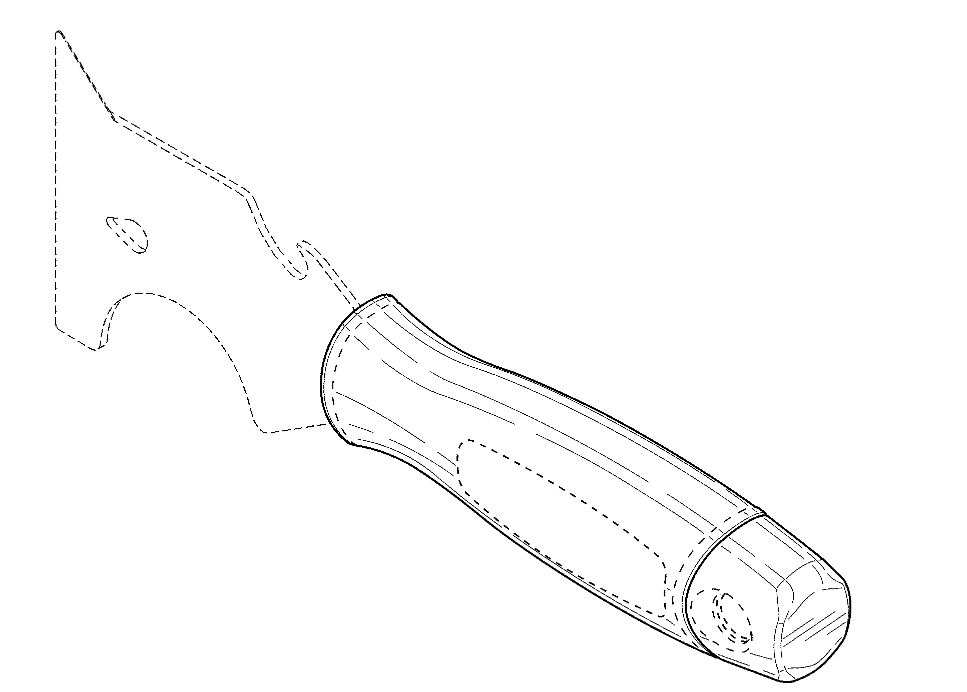
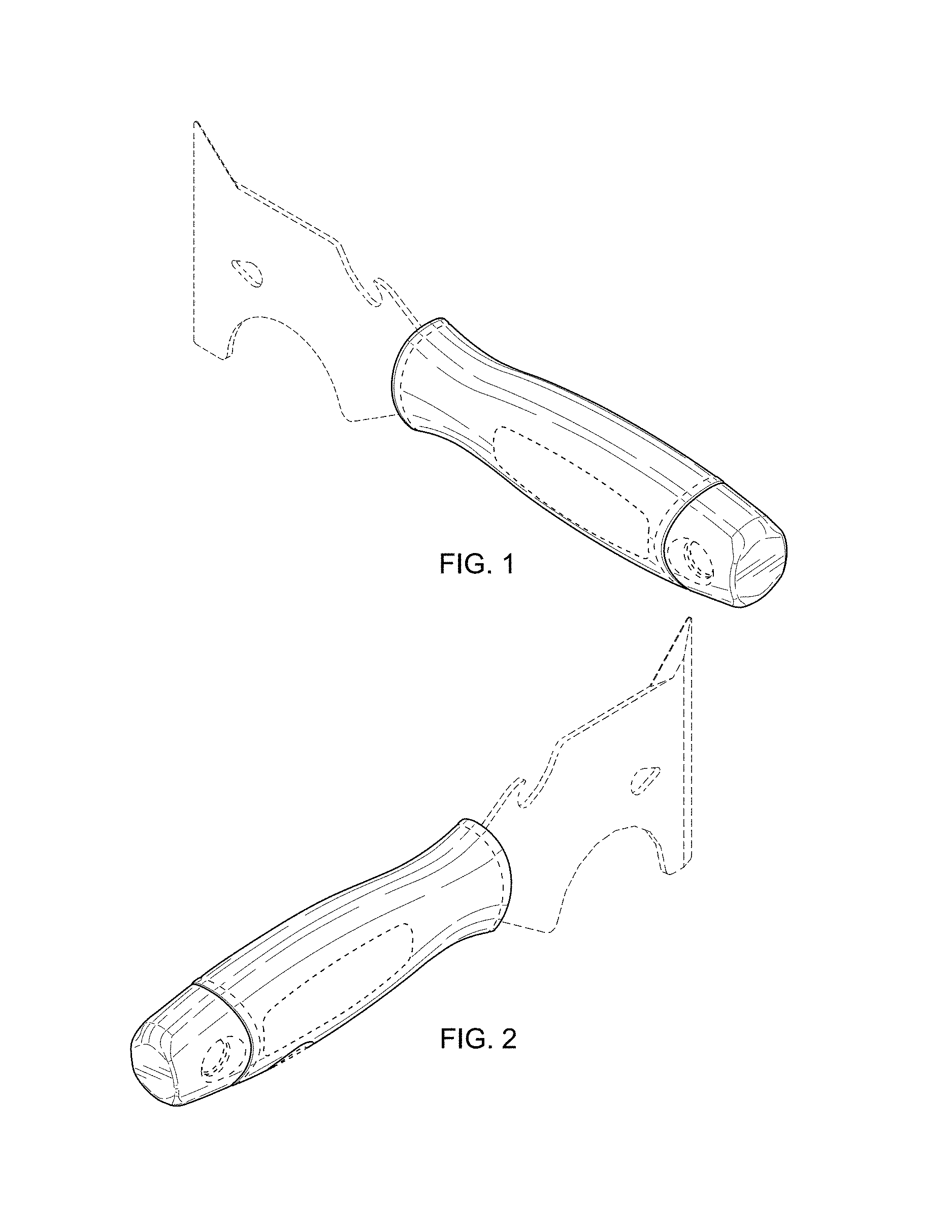
FIG. 1 is a top front perspective view of an embodiment of a multi-tool with bit slot showing a new design;
FIG. 2 is a top rear perspective view of the multi-tool as illustrated in FIG. 1;
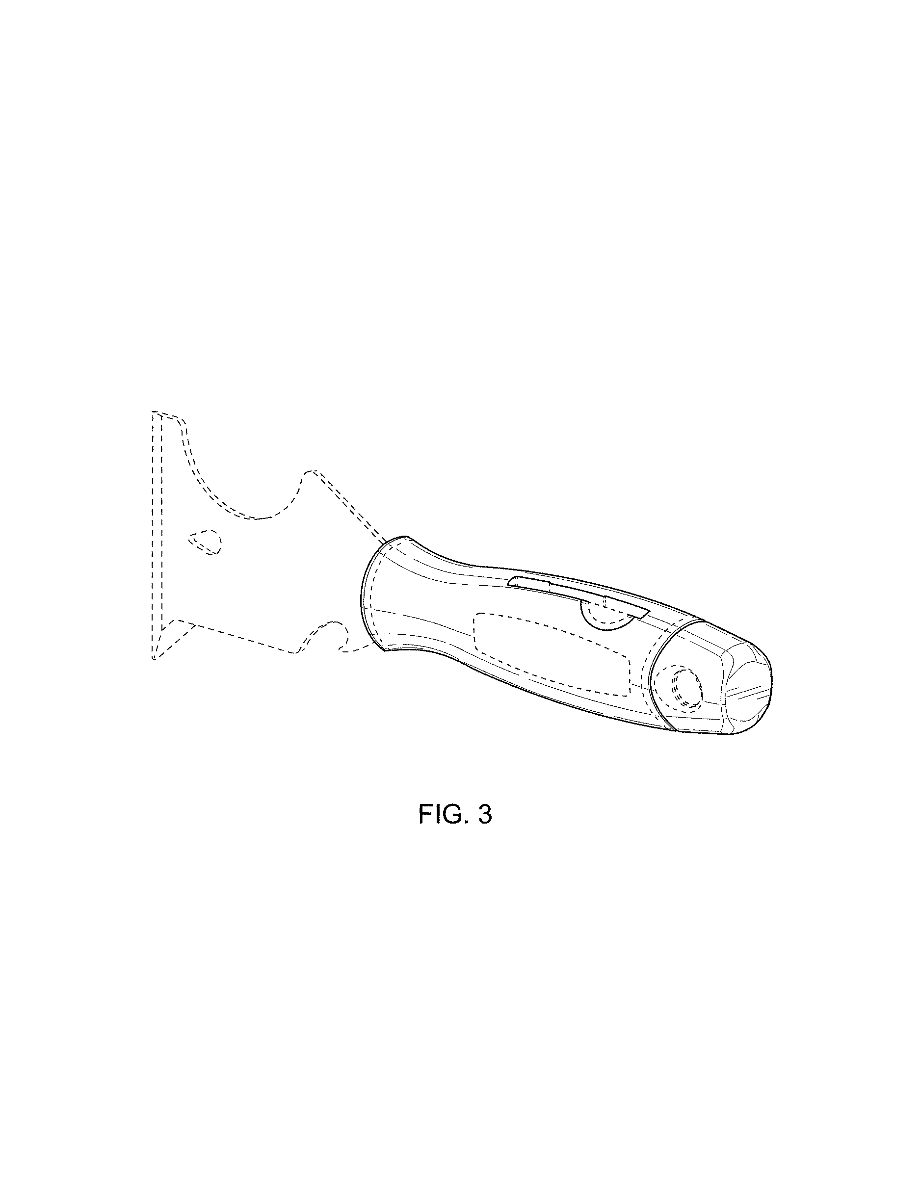
FIG. 3 is a bottom rear perspective view of the multi-tool as illustrated in FIG. 1;
FIG. 4 is a top view of the multi-tool illustrated in FIG. 1;
FIG. 5 is a bottom view of the multi-tool illustrated in FIG. 1;
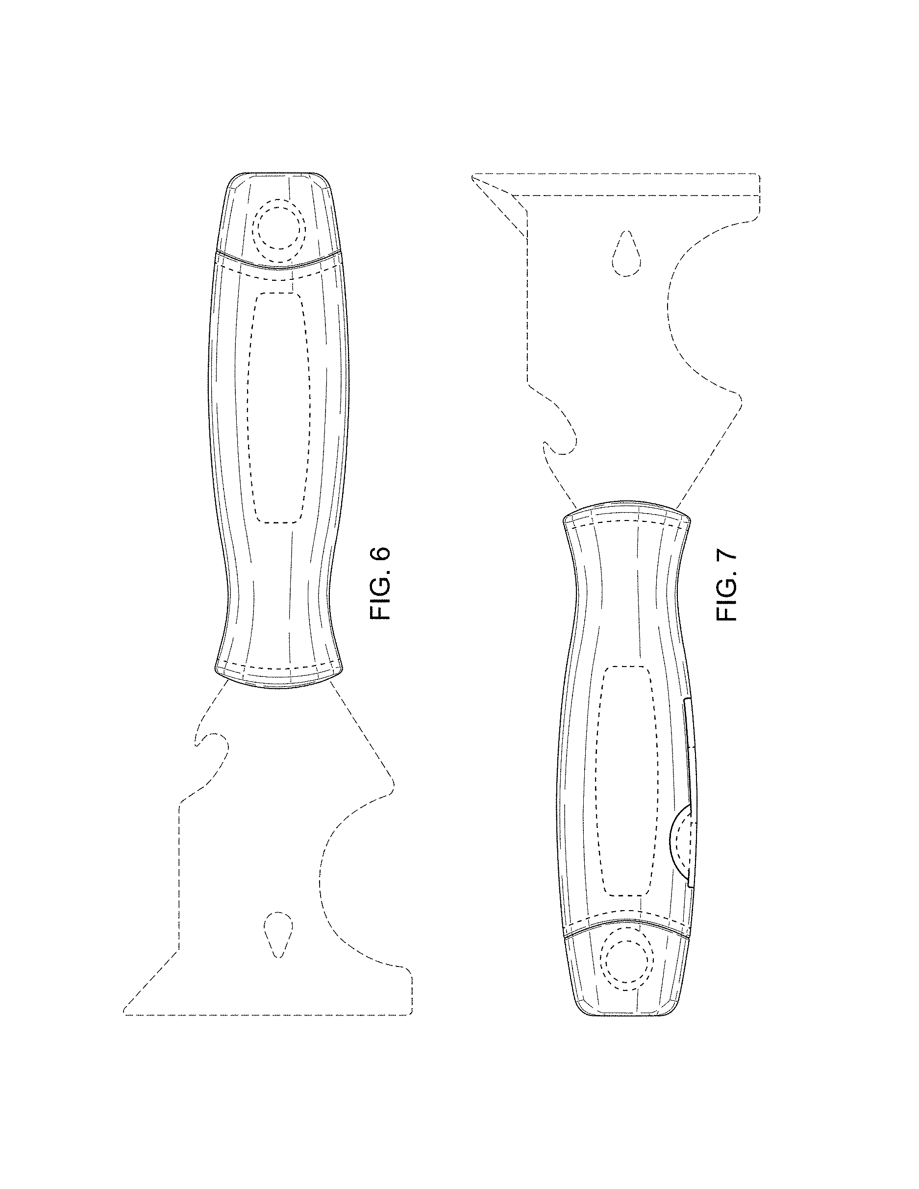
FIG. 6 is a front view of the multi-tool illustrated in FIG. 1;
FIG. 7 is a rear view of the multi-tool illustrated in FIG. 1;
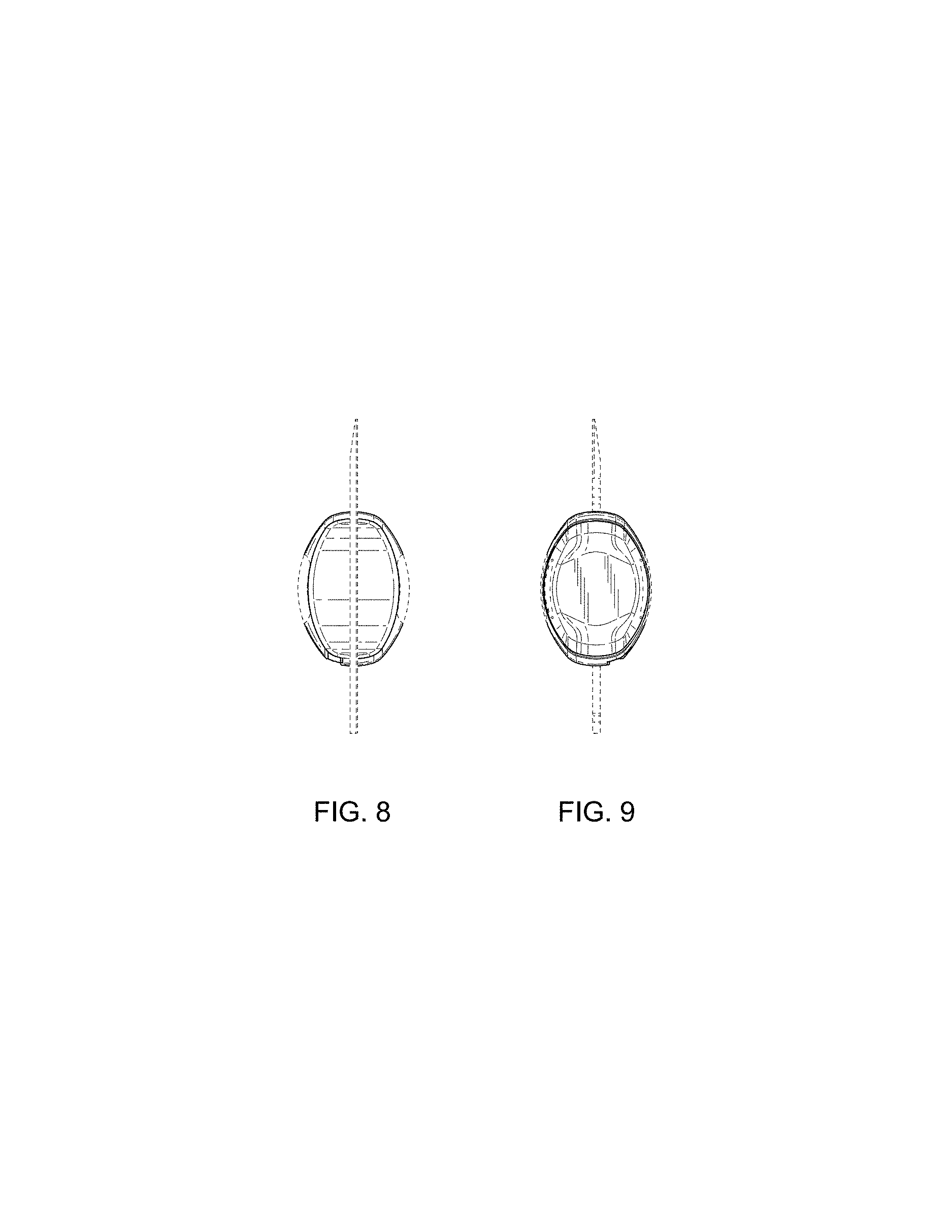
FIG. 8 is a left side view of the multi-tool illustrated in FIG. 1; and,
FIG. 9 is a right side view of the multi-tool illustrated in FIG. 1.
The broken lines depict portions of the multi-tool with bit slot in which the design is embodied that are not considered part of the claimed design.
* * * * *
D00000
D00001
D00002
D00003
D00004
D00005
XML
uspto.report is an independent third-party trademark research tool that is not affiliated, endorsed, or sponsored by the United States Patent and Trademark Office (USPTO) or any other governmental organization. The information provided by uspto.report is based on publicly available data at the time of writing and is intended for informational purposes only.
While we strive to provide accurate and up-to-date information, we do not guarantee the accuracy, completeness, reliability, or suitability of the information displayed on this site. The use of this site is at your own risk. Any reliance you place on such information is therefore strictly at your own risk.
All official trademark data, including owner information, should be verified by visiting the official USPTO website at www.uspto.gov. This site is not intended to replace professional legal advice and should not be used as a substitute for consulting with a legal professional who is knowledgeable about trademark law.