Extender port for making optical connections
Dannoux , et al. Oc
U.S. patent number D864,207 [Application Number D/654,911] was granted by the patent office on 2019-10-22 for extender port for making optical connections. This patent grant is currently assigned to Corning Research & Development Corporation. The grantee listed for this patent is Corning Research & Development Corporation. Invention is credited to Thierry Luc Alain Dannoux, Felix Scotta, Michael Wimmer, Shane Woody.


| United States Patent | D864,207 |
| Dannoux , et al. | October 22, 2019 |
Extender port for making optical connections
Claims
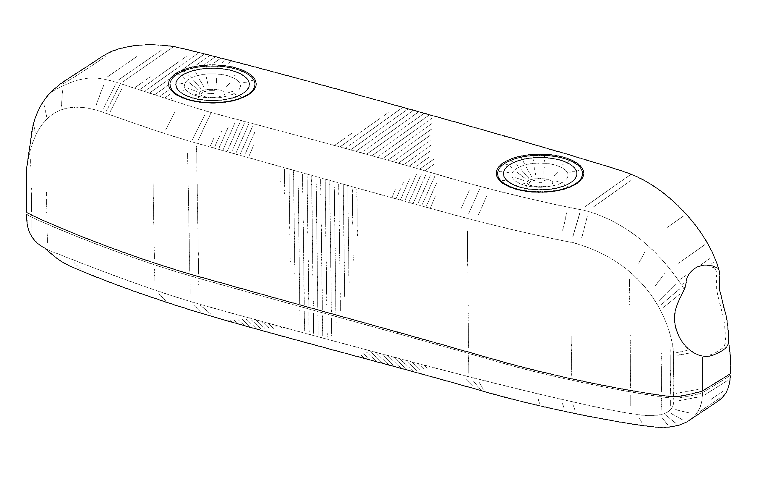
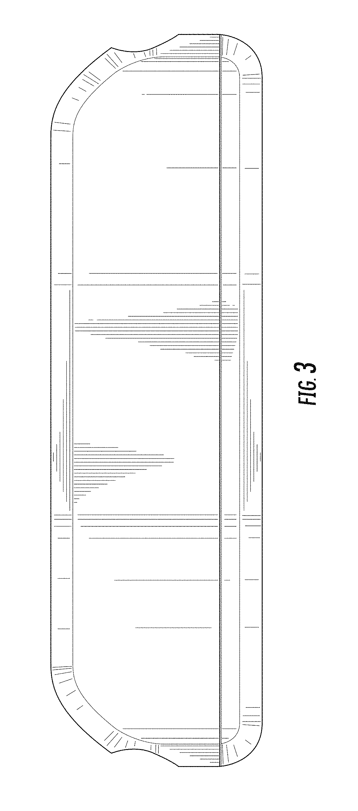
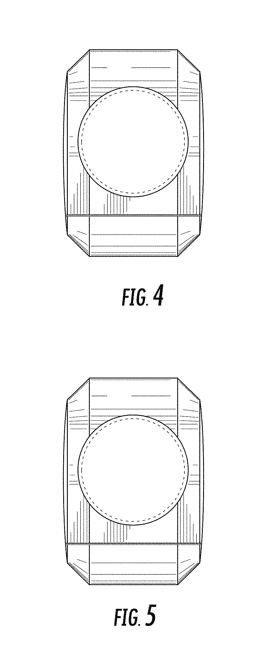
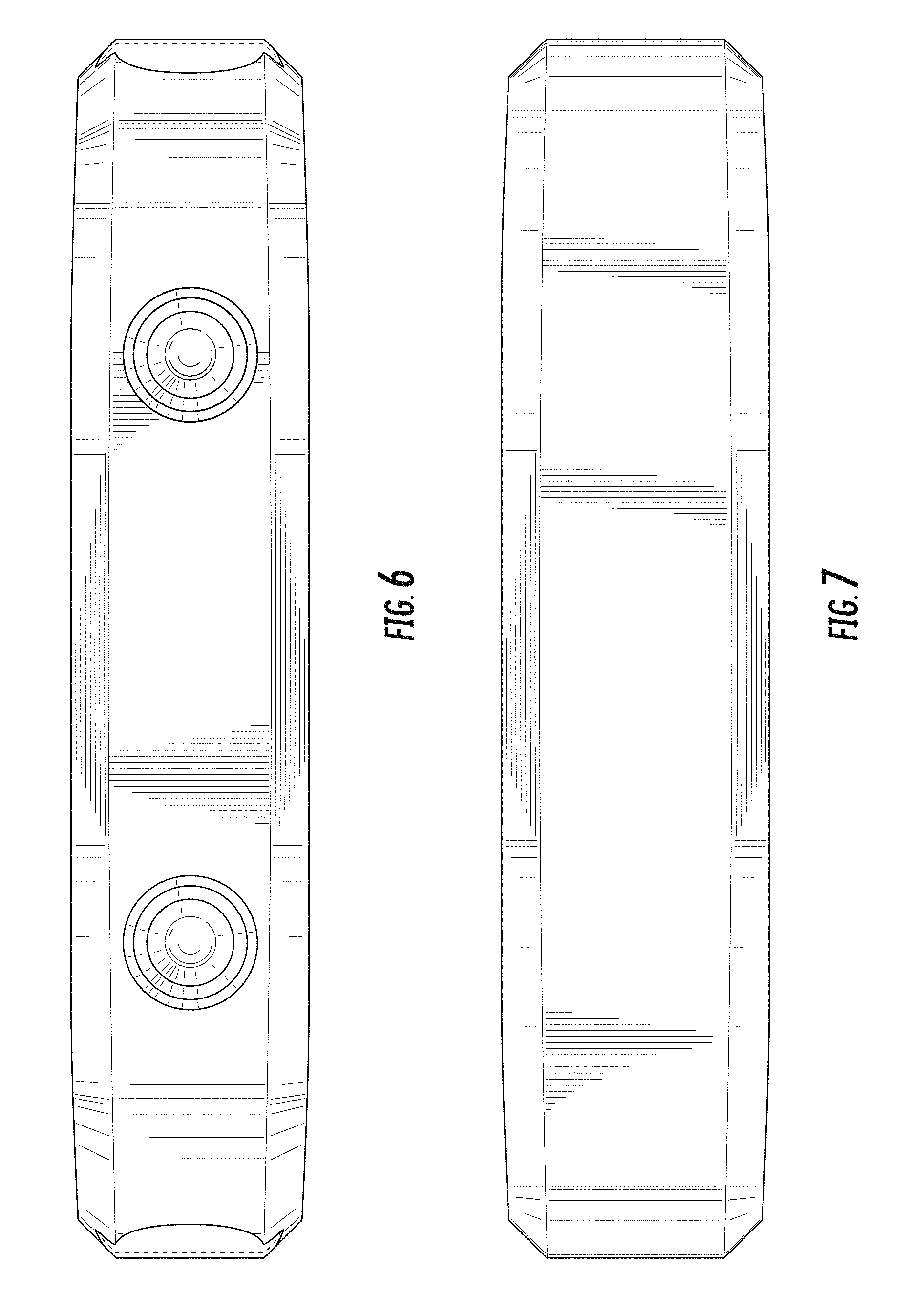
CLAIM The ornamental design for an extender port for making optical connections, as shown and described.
| Inventors: | Dannoux; Thierry Luc Alain (Avon, FR), Scotta; Felix (Savigny le Temple, FR), Wimmer; Michael (Berlin, DE), Woody; Shane (Charlotte, NC) | ||||||||||
|---|---|---|---|---|---|---|---|---|---|---|---|
| Applicant: |
|
||||||||||
| Assignee: | Corning Research & Development
Corporation (Corning, NY) |
||||||||||
| Appl. No.: | D/654,911 | ||||||||||
| Filed: | June 28, 2018 |
| Current U.S. Class: | D14/433 |
| Current International Class: | 1402 |
| Field of Search: | ;D14/356,432-434,453,454,511,203.8,209.1,238.1,240,125 ;439/638,928,105,502 ;710/303,304 ;D13/110,133,146,123,162 |
References Cited [Referenced By]
U.S. Patent Documents
| 5600747 | February 1997 | Yamakawa et al. |
| D559848 | January 2008 | Siu |
| D587269 | February 2009 | Keeports |
| 7753596 | July 2010 | Cox |
| D664146 | July 2012 | Hoehn |
| D678286 | March 2013 | Cheng |
| D734752 | July 2015 | Chen |
| D776659 | January 2017 | Hou |
| D815091 | April 2018 | Nguyen |
| D826942 | August 2018 | Lu |
| 2014/0161397 | June 2014 | Gallegos et al. |
| 2014/0241671 | August 2014 | Koreeda et al. |
| 104064903 | Sep 2014 | CN | |||
| 2009265208 | Nov 2009 | JP | |||
| 05537852 | Jul 2014 | JP | |||
| 05538328 | Jul 2014 | JP | |||
| 2016156610 | Oct 2016 | WO | |||
Attorney, Agent or Firm: Carroll, Jr.; Michael E.
Description
FIG. 1 is a front perspective view of an extender port for making optical connections showing our new design;
FIG. 2 is a front view thereof of FIG. 1;
FIG. 3 is a rear view thereof of FIG. 1;
FIG. 4 is a right side view thereof of FIG. 1;
FIG. 5 is a left side view thereof of FIG. 1;
FIG. 6 is a top view thereof of FIG. 1; and,
FIG. 7 is a bottom view thereof of FIG. 1.
In FIGS. 1, 4, 5, and 6, the broken lines represent the bounds of the claim and form no part of the claimed design.
* * * * *
D00000
D00001
D00002
D00003
D00004
D00005
XML
uspto.report is an independent third-party trademark research tool that is not affiliated, endorsed, or sponsored by the United States Patent and Trademark Office (USPTO) or any other governmental organization. The information provided by uspto.report is based on publicly available data at the time of writing and is intended for informational purposes only.
While we strive to provide accurate and up-to-date information, we do not guarantee the accuracy, completeness, reliability, or suitability of the information displayed on this site. The use of this site is at your own risk. Any reliance you place on such information is therefore strictly at your own risk.
All official trademark data, including owner information, should be verified by visiting the official USPTO website at www.uspto.gov. This site is not intended to replace professional legal advice and should not be used as a substitute for consulting with a legal professional who is knowledgeable about trademark law.