Titrator
Staton , et al. Oc
U.S. patent number D864,000 [Application Number D/667,721] was granted by the patent office on 2019-10-22 for titrator. This patent grant is currently assigned to THERMO ORION INC.. The grantee listed for this patent is THERMO ORION INC.. Invention is credited to William A. Liberis, Jr., Mohan Rajasekaran, John M. Staton, Aaron Szymanski.

| United States Patent | D864,000 |
| Staton , et al. | October 22, 2019 |
Titrator
Claims
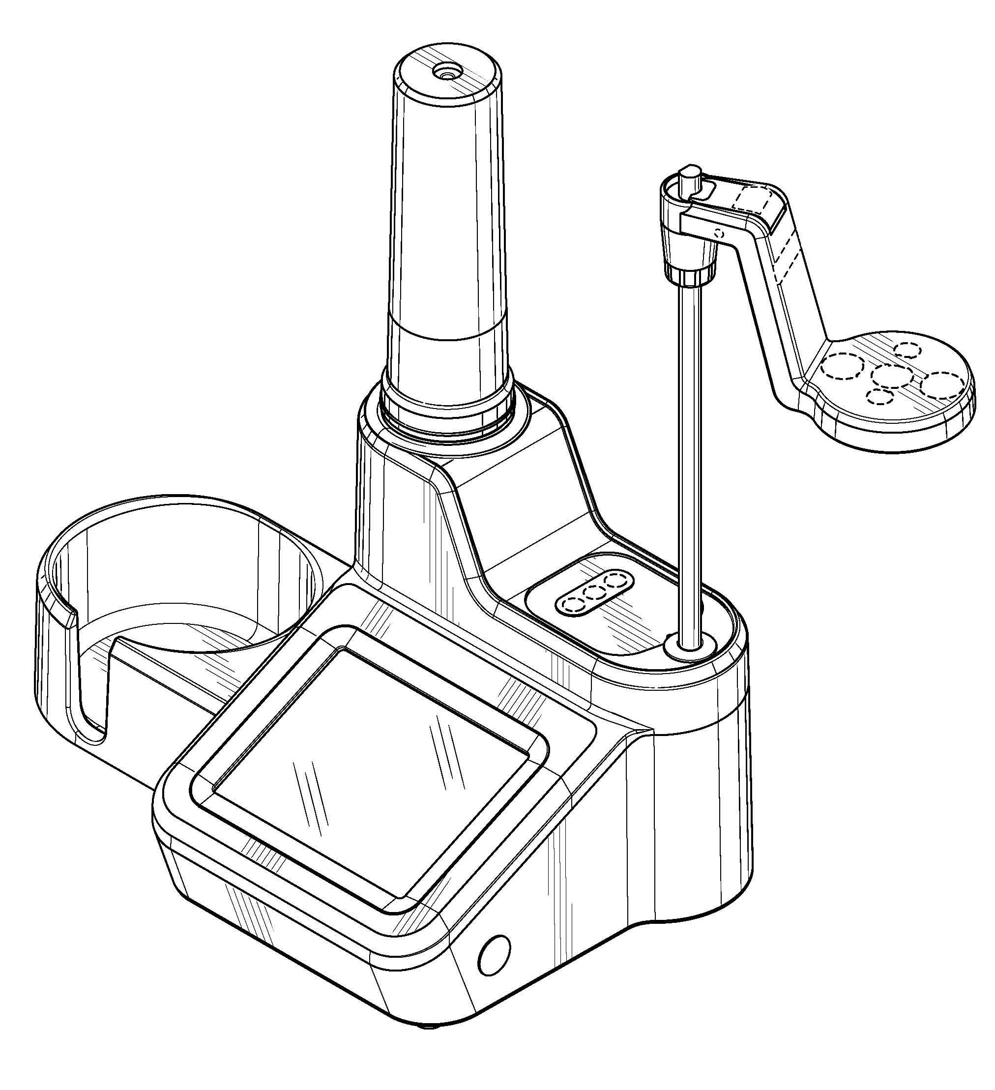
CLAIM The ornamental design for a titrator, as shown and described.
| Inventors: | Staton; John M. (Waltham, MA), Liberis, Jr.; William A. (Somerville, MA), Szymanski; Aaron (Thomaston, CT), Rajasekaran; Mohan (Bristol, CT) | ||||||||||
|---|---|---|---|---|---|---|---|---|---|---|---|
| Applicant: |
|
||||||||||
| Assignee: | THERMO ORION INC. (Chelmsford,
MA) |
||||||||||
| Appl. No.: | D/667,721 | ||||||||||
| Filed: | October 24, 2018 |
Related U.S. Patent Documents
| Application Number | Filing Date | Patent Number | Issue Date | ||
|---|---|---|---|---|---|
| 29608514 | Jun 22, 2017 | D836014 | |||
| Current U.S. Class: | D10/81; D24/216 |
| Current International Class: | 1004 |
| Field of Search: | ;D10/81 ;D24/216,232,233,234 |
References Cited [Referenced By]
U.S. Patent Documents
| D417634 | December 1999 | Aebi |
Attorney, Agent or Firm: Wood Herron & Evans LLP
Description
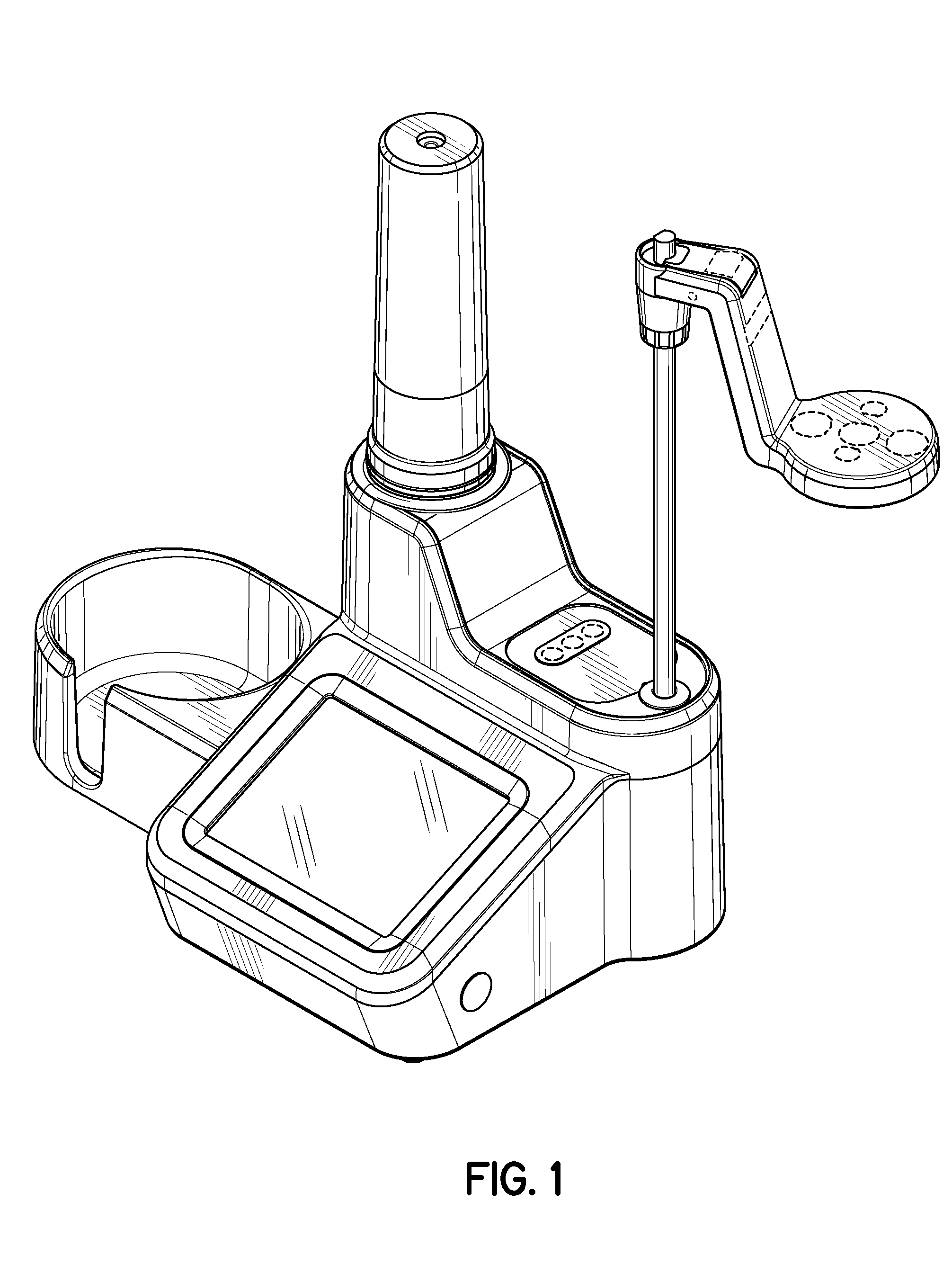
FIG. 1 is a front right perspective view of our new titrator design;
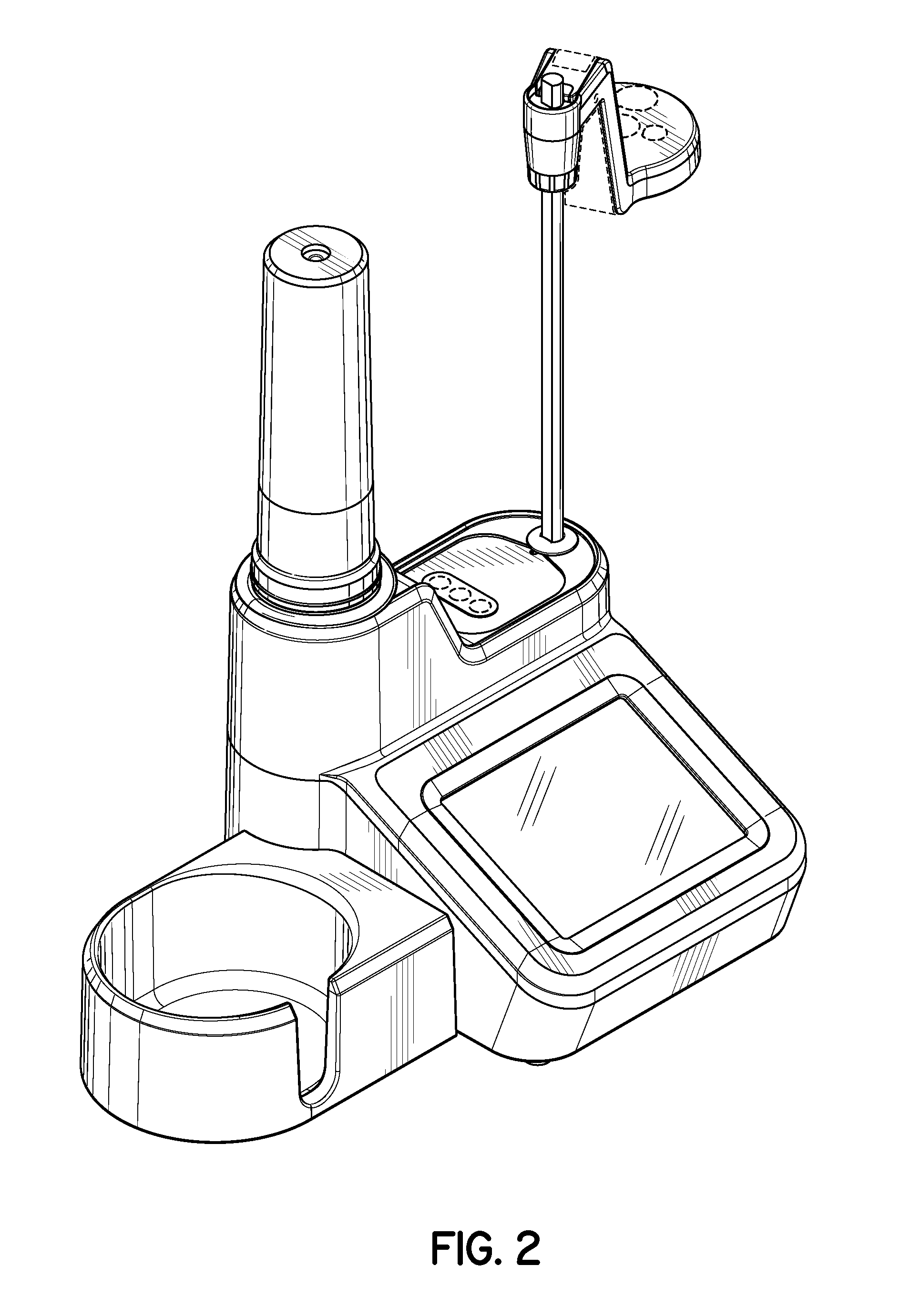
FIG. 2 is a front left perspective view of the titrator of FIG. 1;
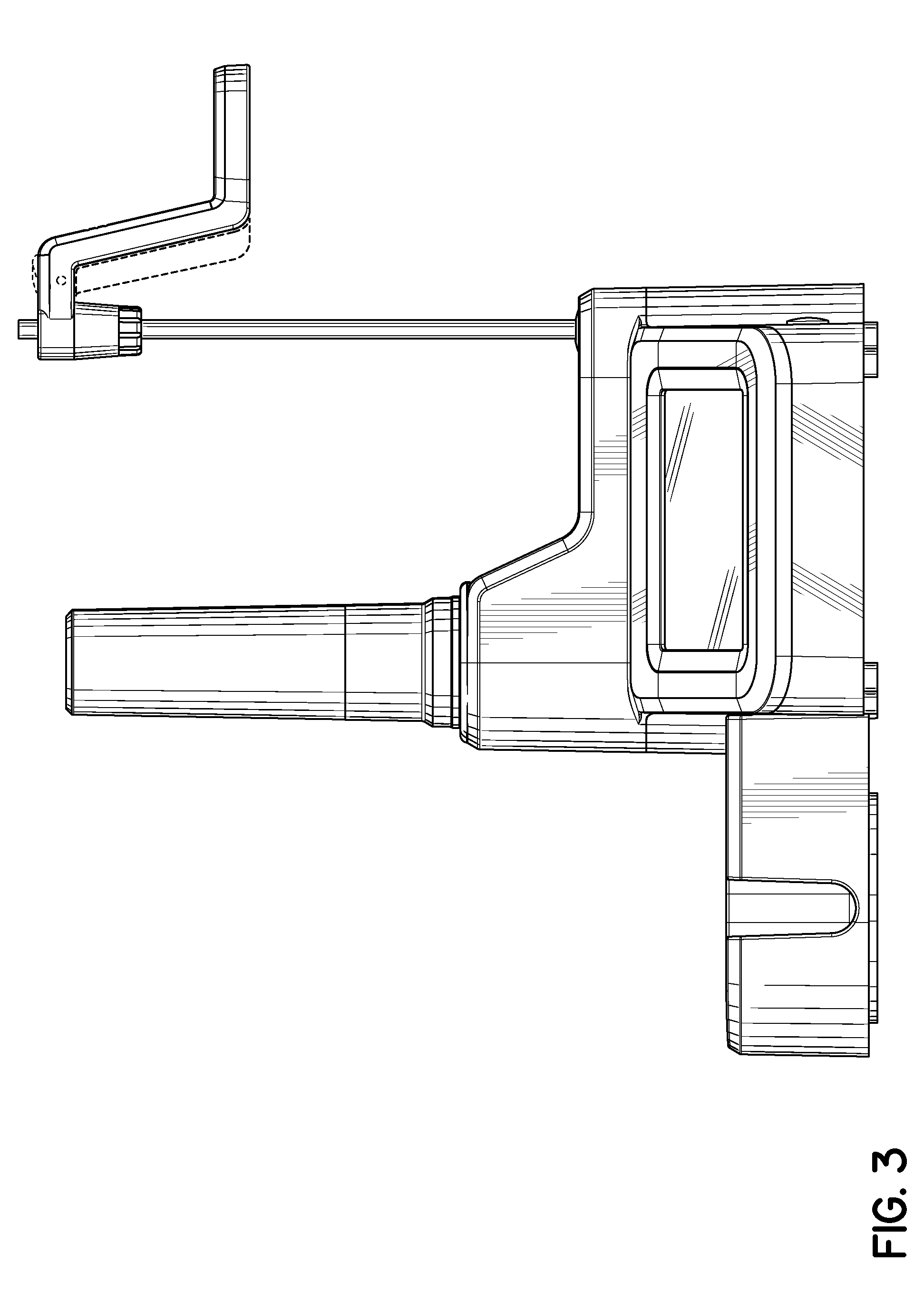
FIG. 3 is a front view of the titrator of FIG. 1;
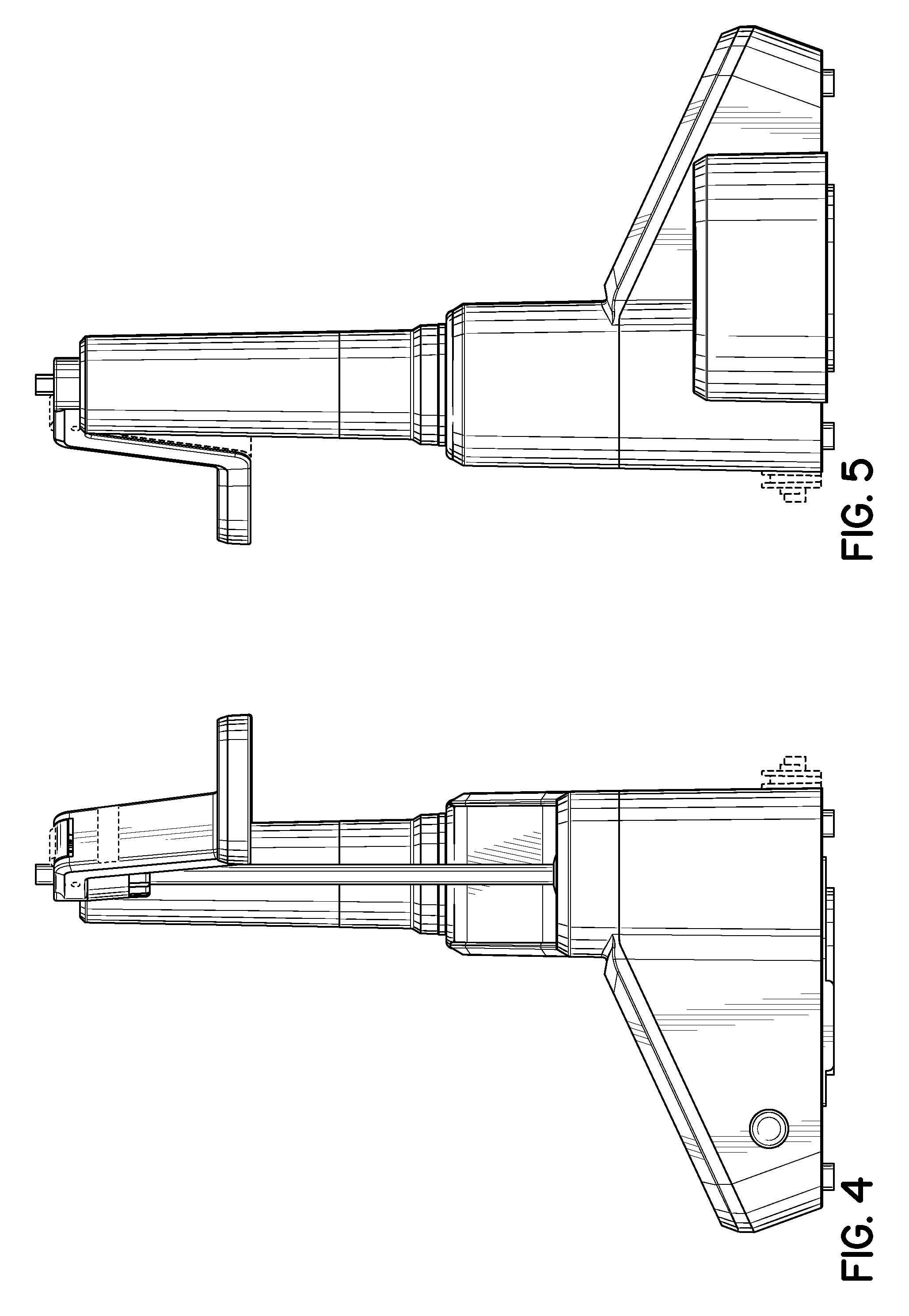
FIG. 4 is a right side view of the titrator of FIG. 1;
FIG. 5 is a left side view of the titrator of FIG. 1;
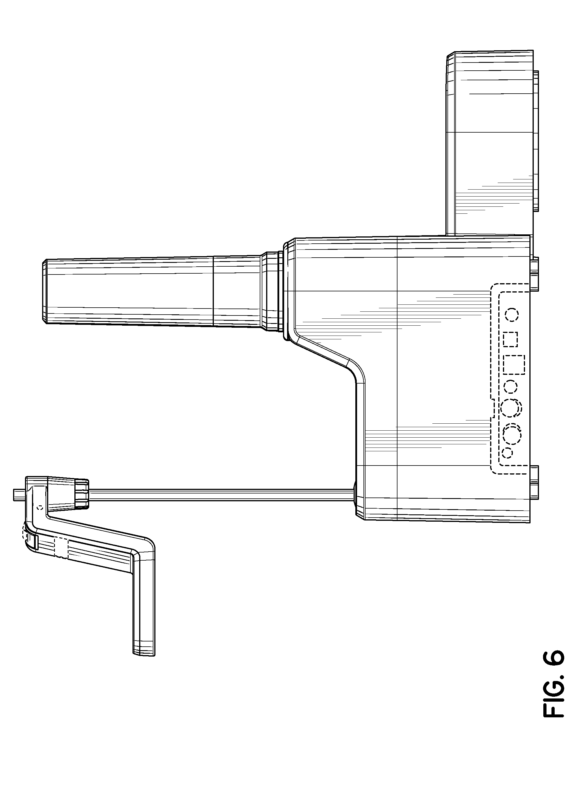
FIG. 6 is a rear view of the titrator of FIG. 1;
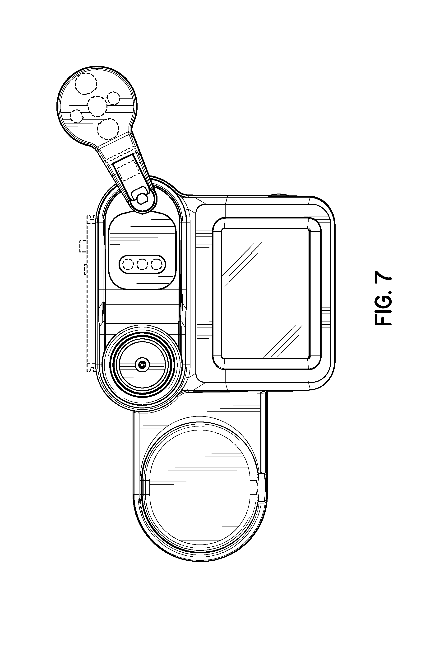
FIG. 7 is a top view of the titrator of FIG. 1; and,
FIG. 8 is a bottom view of the titrator of FIG. 1.
The features of the titrator shown in broken lines are for illustrative purposes only and form no part of the claimed design.
* * * * *
D00000
D00001
D00002
D00003
D00004
D00005
D00006
D00007
XML
uspto.report is an independent third-party trademark research tool that is not affiliated, endorsed, or sponsored by the United States Patent and Trademark Office (USPTO) or any other governmental organization. The information provided by uspto.report is based on publicly available data at the time of writing and is intended for informational purposes only.
While we strive to provide accurate and up-to-date information, we do not guarantee the accuracy, completeness, reliability, or suitability of the information displayed on this site. The use of this site is at your own risk. Any reliance you place on such information is therefore strictly at your own risk.
All official trademark data, including owner information, should be verified by visiting the official USPTO website at www.uspto.gov. This site is not intended to replace professional legal advice and should not be used as a substitute for consulting with a legal professional who is knowledgeable about trademark law.