Socket wrench selector
Albertson Oc
U.S. patent number D863,005 [Application Number D/651,054] was granted by the patent office on 2019-10-15 for socket wrench selector. The grantee listed for this patent is Robert V. Albertson. Invention is credited to Robert V. Albertson.


View All Diagrams
| United States Patent | D863,005 |
| Albertson | October 15, 2019 |
Socket wrench selector
Claims
CLAIM The ornamental design of a socket wrench selector, as shown and described.
| Inventors: | Albertson; Robert V. (Mound, MN) | ||||||||||
|---|---|---|---|---|---|---|---|---|---|---|---|
| Applicant: |
|
||||||||||
| Appl. No.: | D/651,054 | ||||||||||
| Filed: | November 14, 2017 |
| Current U.S. Class: | D8/25 |
| Current International Class: | 0805 |
| Field of Search: | ;81/58,58.1,59.1,60,61,62,63,63.1,63.2,121.1,125,177.1,177.2,177.85,180.1,489 ;D8/25 ;192/44 |
References Cited [Referenced By]
U.S. Patent Documents
| 5216940 | June 1993 | Hedden |
| 5259278 | November 1993 | Leas |
| 5603248 | February 1997 | Eggert et al. |
| 5761973 | June 1998 | Tung |
| 5970825 | October 1999 | Barnet et al. |
| 6067881 | May 2000 | Albertson |
| 6276239 | August 2001 | Albertson |
| 6516688 | February 2003 | Albertson |
| 6601476 | August 2003 | Hu |
| 6748824 | June 2004 | Chen |
| 6782777 | August 2004 | Wei |
| D521824 | May 2006 | Albertson et al. |
| 7077032 | July 2006 | Lee |
| D529778 | October 2006 | Albertson |
| 8297152 | October 2012 | Hu |
| 8904907 | December 2014 | Douglass |
| D727120 | April 2015 | Wang |
| 9156144 | October 2015 | Gummow |
| D749384 | February 2016 | Chang |
| D797531 | September 2017 | Albertson |
| 2003/0126957 | July 2003 | Huang |
| 2007/0163398 | July 2007 | Lai Lee |
Attorney, Agent or Firm: Barte; Richard John
Description
FIG. 1 is a perspective view of a first embodiment of the socket wrench selector of my design;
FIG. 2 is a top plan view thereof;
FIG. 3 is a bottom plan view thereof;
FIG. 4 is a front elevational view thereof;
FIG. 5 is a rear elevational view thereof;
FIG. 6 is a left side elevational view thereof;
FIG. 7 is a right side elevational view thereof;
FIG. 8 is a sectional view taken along line 8-8 of FIG. 2;
FIG. 9 is a sectional view taken along line 9-9 of FIG. 2;
FIG. 10 is a sectional view taken along line 10-10 of FIG. 4;
FIG. 11 is a perspective view of a second embodiment of the socket wrench selector of my design;
FIG. 12 is a top plan view of FIG. 11;
FIG. 13 is a bottom plan view of FIG. 11;
FIG. 14 is a front elevational view of FIG. 11;
FIG. 15 is a rear elevational view of FIG. 11;
FIG. 16 is a left side elevational view of FIG. 11;
FIG. 17 is a right side elevational view of FIG. 11;
FIG. 18 is a sectional view taken along line 18-18 of FIG. 12;
FIG. 19 is a sectional view taken along line 19-19 of FIG. 12;
FIG. 20 is a sectional view taken along line 20-20 of FIG. 14;
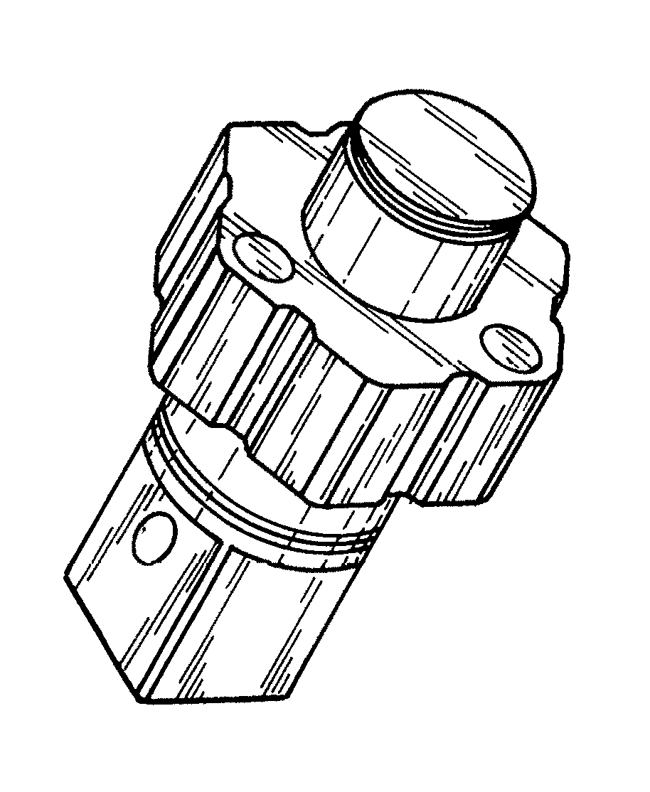
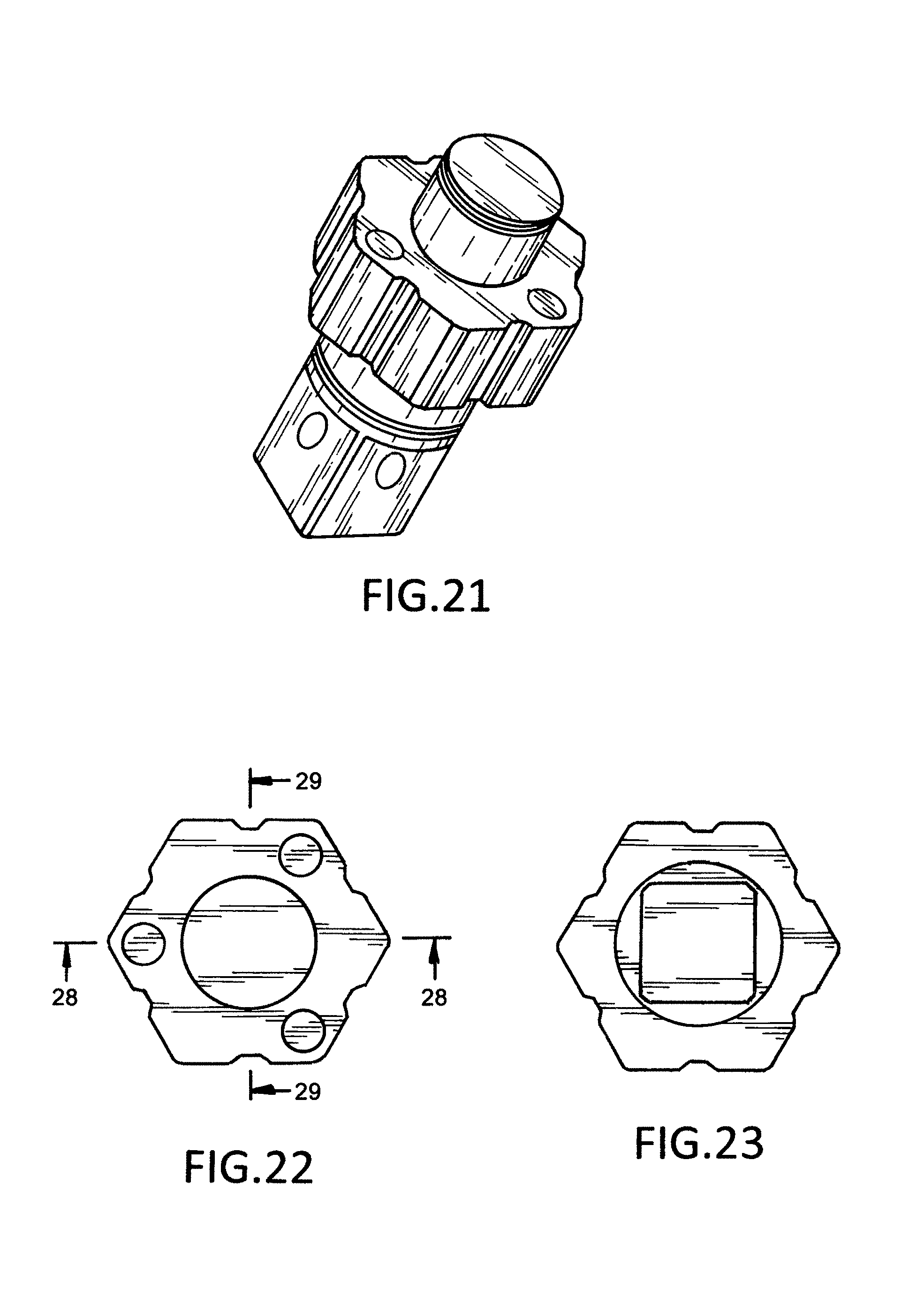
FIG. 21 is a perspective view of a third embodiment of the socket wrench selector of my design;
FIG. 22 is a top plan view of FIG. 21;
FIG. 23 is a bottom plan view of FIG. 21;
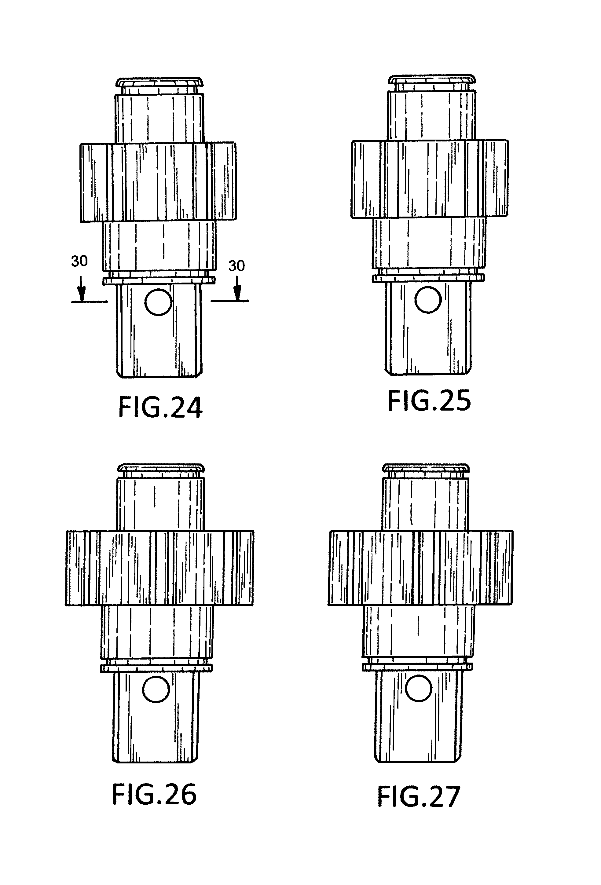
FIG. 24 is a front elevational view of FIG. 21;
FIG. 25 is a rear elevational view of FIG. 21;
FIG. 26 is a left side elevational view of FIG. 21;
FIG. 27 is a right side elevational view of FIG. 21;
FIG. 28 is a sectional view taken along line 28-28 of FIG. 22;
FIG. 29 is a sectional view taken along line 29-29 of FIG. 22;
FIG. 30 is a sectional view taken along line 30-30 of FIG. 24;
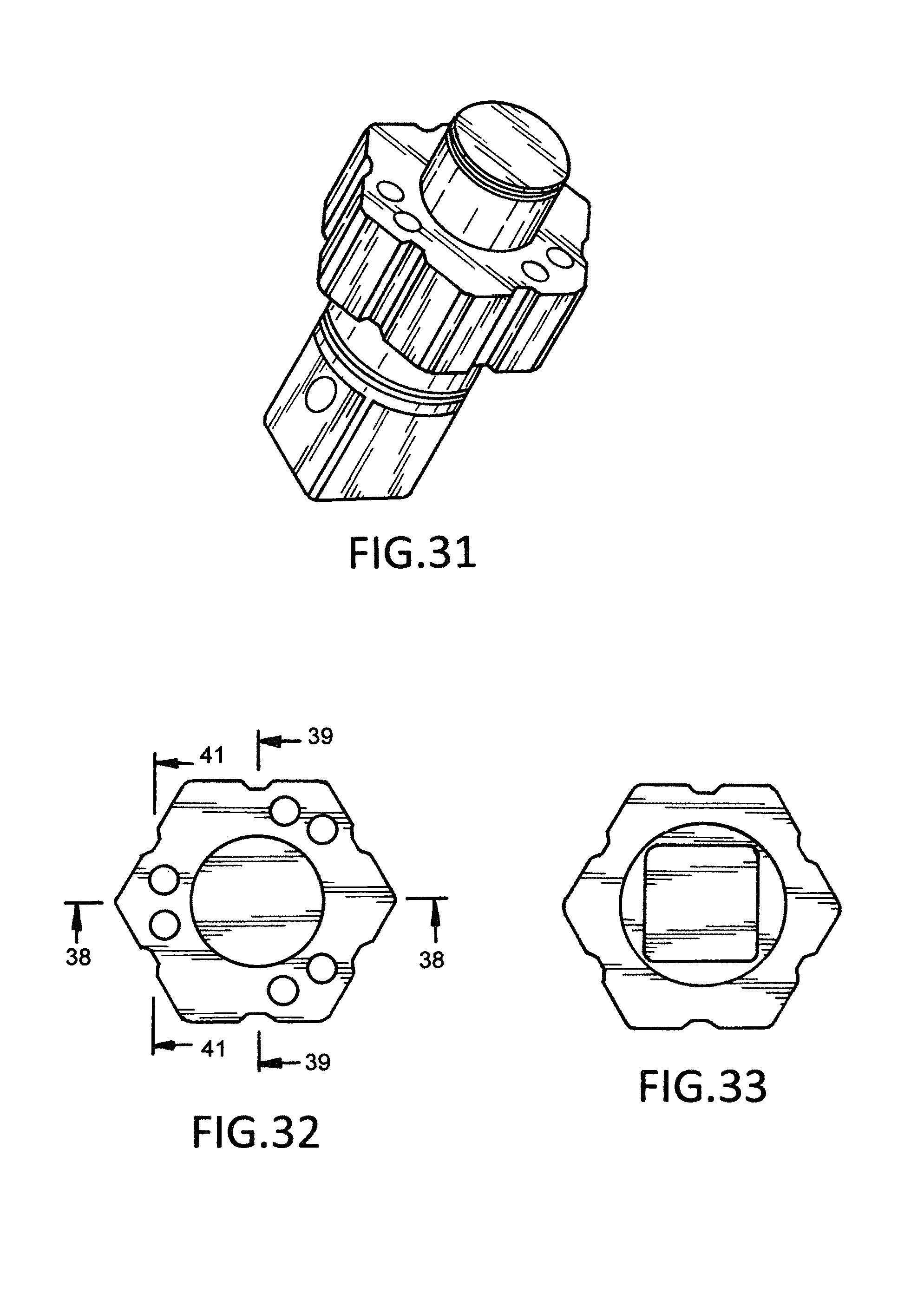
FIG. 31 is a perspective view of a fourth embodiment of the socket wrench selector of my design;
FIG. 32 is a top plan view of FIG. 31;
FIG. 33 is a bottom plan view of FIG. 31;
FIG. 34 is a front elevational view of FIG. 31;
FIG. 35 is a rear elevational view of FIG. 31;
FIG. 36 is a left side elevational view of FIG. 31;
FIG. 37 is a right side elevational view of FIG. 31;
FIG. 38 is a sectional view taken along line 38-38 of FIG. 32;
FIG. 39 is a sectional view taken along line 39-39 of FIG. 32;
FIG. 40 is a sectional view taken along line 40-40 of FIG. 34;
FIG. 41 is a sectional view taken along line 41-41 of FIG. 32;
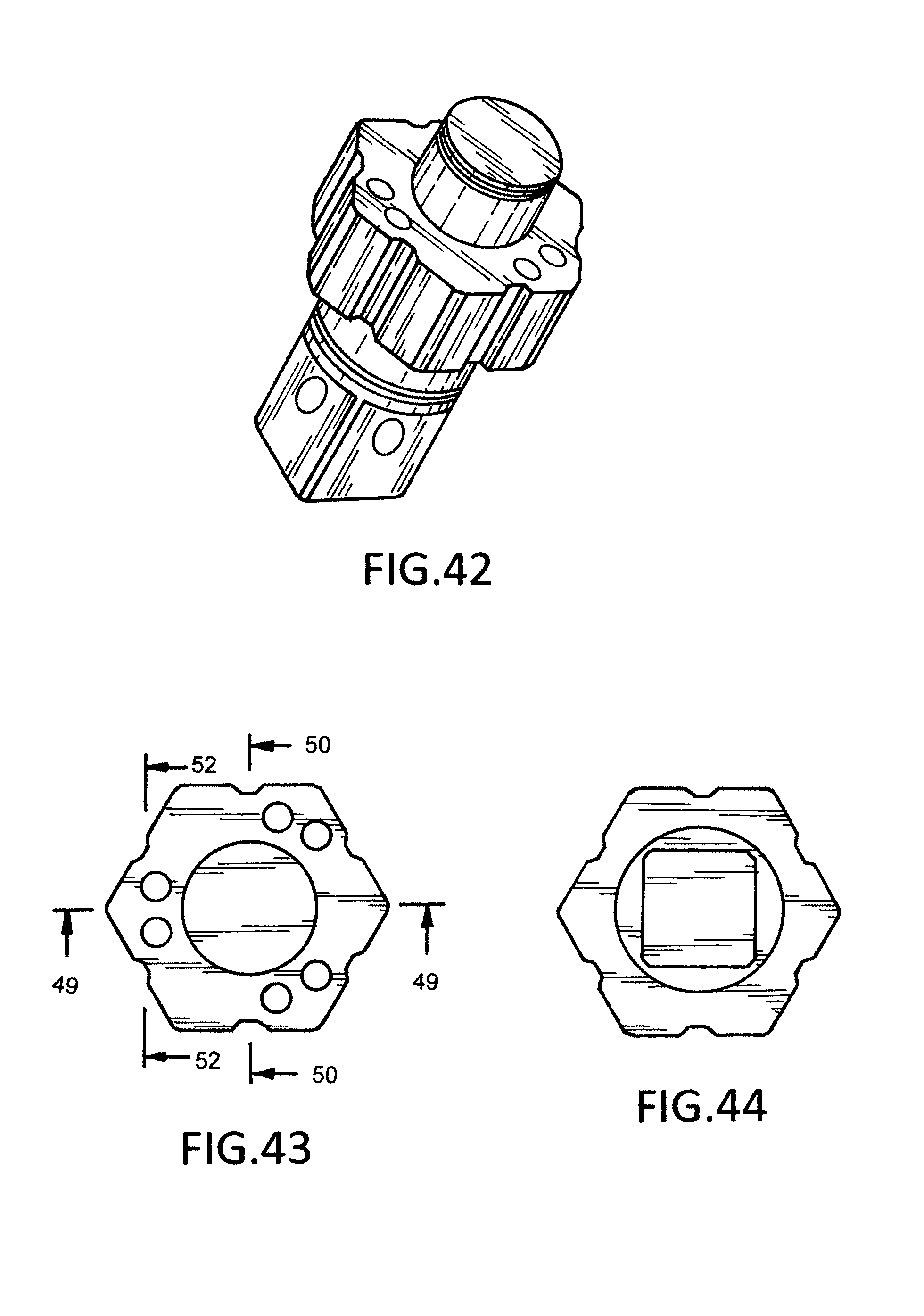
FIG. 42 is a perspective view of a fifth embodiment of the socket wrench selector of my design;
FIG. 43 is a top plan view of FIG. 42;
FIG. 44 is a bottom plan view of FIG. 42;
FIG. 45 is a front elevational view of FIG. 42;
FIG. 46 is a rear elevational view of FIG. 42;
FIG. 47 is a left side elevational view of FIG. 42;
FIG. 48 is a right side elevational view of FIG. 42;
FIG. 49 is a sectional view taken along line 48-48 of FIG. 43;
FIG. 50 is a sectional view taken along line 50-50 of FIG. 43;
FIG. 51 is a sectional view taken along line 51-51 of FIG. 45;
FIG. 52 is a sectional view taken along line 52-52 of FIG. 43;
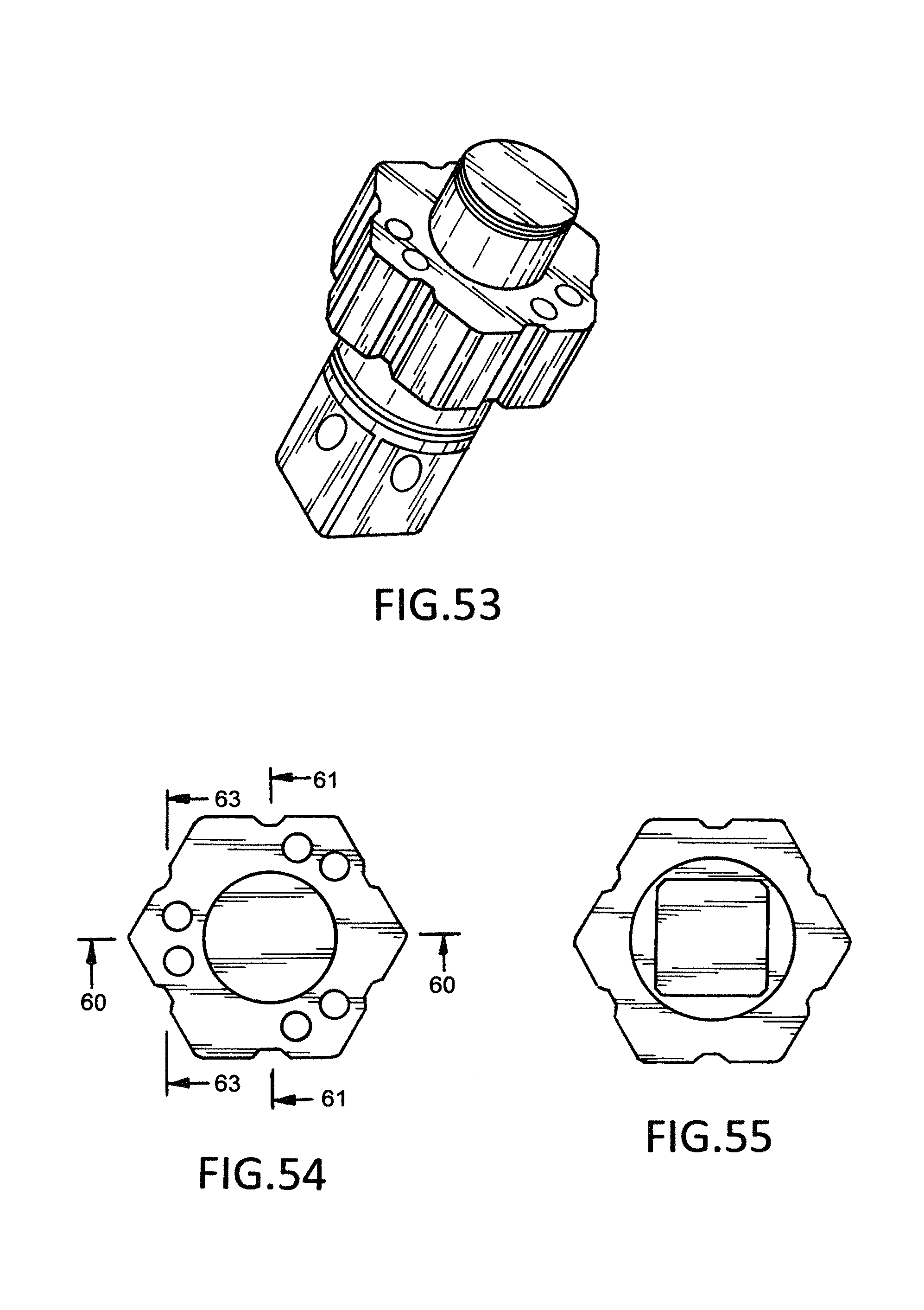
FIG. 53 is a perspective view of a sixth embodiment of the socket wrench selector of my design;
FIG. 54 is a top plan view of FIG. 53;
FIG. 55 is a bottom plan view of FIG. 53;
FIG. 56 is a front elevational view of FIG. 53;
FIG. 57 is a rear elevational view of FIG. 53;
FIG. 58 is a left side elevational view of FIG. 53;
FIG. 59 is a right side elevational view of FIG. 53;
FIG. 60 is a sectional view taken along line 60-60 of FIG. 54;
FIG. 61 is a sectional view taken along line 61-61 of FIG. 54;
FIG. 62 is a sectional view taken along line 62-62 of FIG. 56; and,
FIG. 63 is a sectional view taken along line 63-63 of FIG. 54.
* * * * *
D00000
D00001
D00002
D00003
D00004
D00005
D00006
D00007
D00008
D00009
D00010
D00011
D00012

D00013
D00014

D00015

D00016
D00017

D00018

XML
uspto.report is an independent third-party trademark research tool that is not affiliated, endorsed, or sponsored by the United States Patent and Trademark Office (USPTO) or any other governmental organization. The information provided by uspto.report is based on publicly available data at the time of writing and is intended for informational purposes only.
While we strive to provide accurate and up-to-date information, we do not guarantee the accuracy, completeness, reliability, or suitability of the information displayed on this site. The use of this site is at your own risk. Any reliance you place on such information is therefore strictly at your own risk.
All official trademark data, including owner information, should be verified by visiting the official USPTO website at www.uspto.gov. This site is not intended to replace professional legal advice and should not be used as a substitute for consulting with a legal professional who is knowledgeable about trademark law.