Dental matrix device
Webster , et al. Sept
U.S. patent number D861,174 [Application Number D/674,374] was granted by the patent office on 2019-09-24 for dental matrix device. This patent grant is currently assigned to ULTRADENT PRODUCTS, INC.. The grantee listed for this patent is ULTRADENT PRODUCTS, INC.. Invention is credited to Bruce S. McLean, Wade Robert Michael Smith, Thomas John Webster.


| United States Patent | D861,174 |
| Webster , et al. | September 24, 2019 |
Dental matrix device
Claims
CLAIM The ornamental design for a dental matrix device, as shown and described.
| Inventors: | Webster; Thomas John (Riverton, UT), McLean; Bruce S. (Sandy, UT), Smith; Wade Robert Michael (Pleasant Grove, UT) | ||||||||||
|---|---|---|---|---|---|---|---|---|---|---|---|
| Applicant: |
|
||||||||||
| Assignee: | ULTRADENT PRODUCTS, INC. (South
Jordan, UT) |
||||||||||
| Appl. No.: | D/674,374 | ||||||||||
| Filed: | December 20, 2018 |
Related U.S. Patent Documents
| Application Number | Filing Date | Patent Number | Issue Date | ||
|---|---|---|---|---|---|
| 29615173 | Aug 25, 2017 | ||||
| Current U.S. Class: | D24/181 |
| Current International Class: | 2402 |
| Field of Search: | ;D24/176-182,152 ;433/39,139,223 |
References Cited [Referenced By]
U.S. Patent Documents
| 2286021 | June 1942 | Stanford |
| 2439703 | June 1946 | Tofflemire |
| 3462841 | August 1969 | Ainsworth |
| 5055045 | October 1991 | Dickie et al. |
| 5342197 | August 1994 | Stein et al. |
| 5460525 | October 1995 | Rashid |
| 6074210 | June 2000 | Garrison |
| 6234793 | May 2001 | Brattesani et al. |
| 6589053 | July 2003 | Bills |
| 8517732 | August 2013 | Segal |
| 9517110 | December 2016 | McDonald |
| 9687970 | June 2017 | Chen |
| D792594 | July 2017 | Nicholson |
| 2011/0244421 | October 2011 | Segal et al. |
| 2018/0008375 | January 2018 | Nicholson |
| 2019/0060032 | February 2019 | Webster |
| 2010061161 | Jun 2010 | WO | |||
Attorney, Agent or Firm: Maschoff Brennan
Description
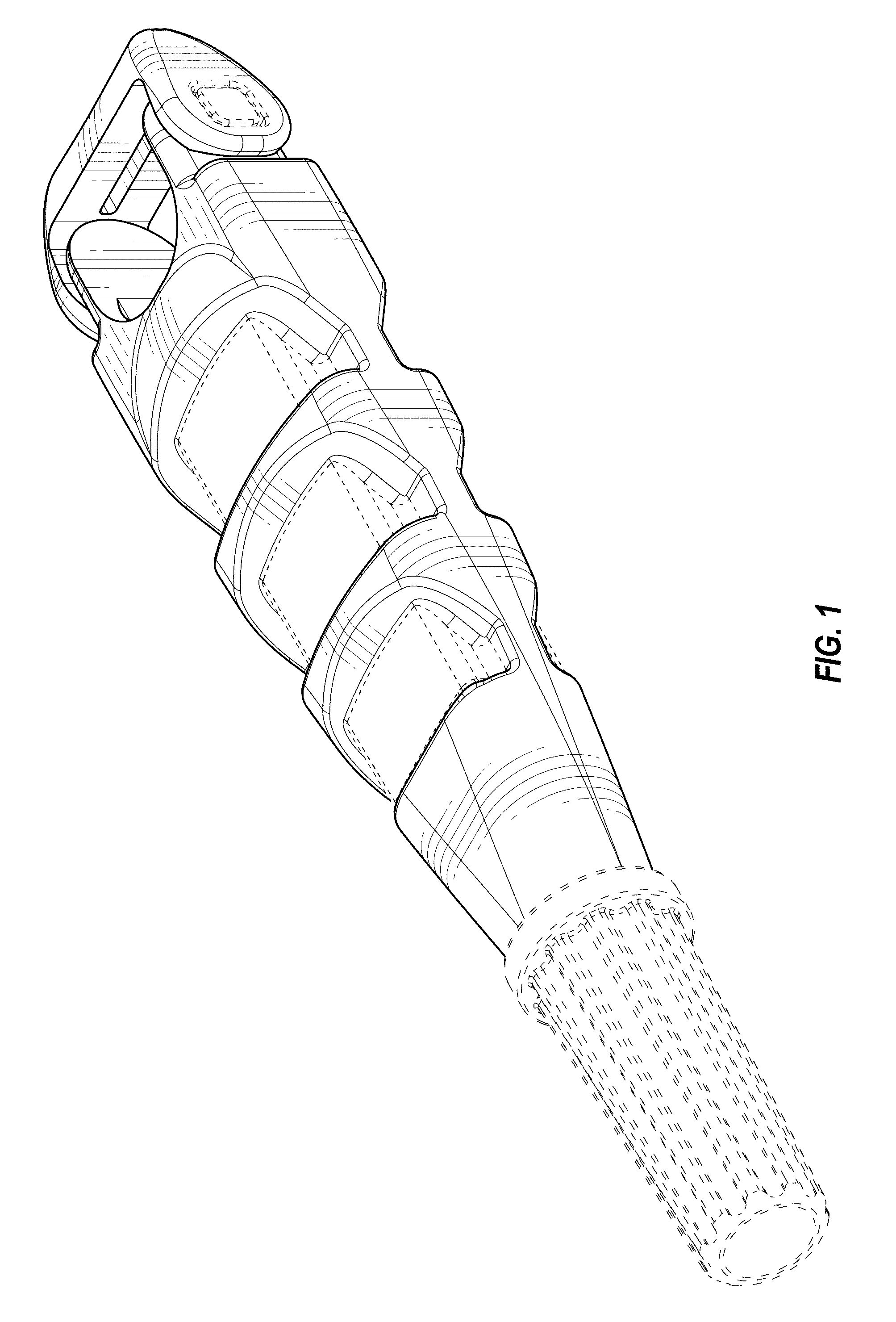
FIG. 1 is an upper perspective view of an embodiment of a dental matrix device;
FIG. 2 is a lower perspective view of the dental matrix device of FIG. 1;
FIG. 3 is a rear view of the dental matrix device of FIG. 1;
FIG. 4 is a front view of the dental matrix device of FIG. 1;
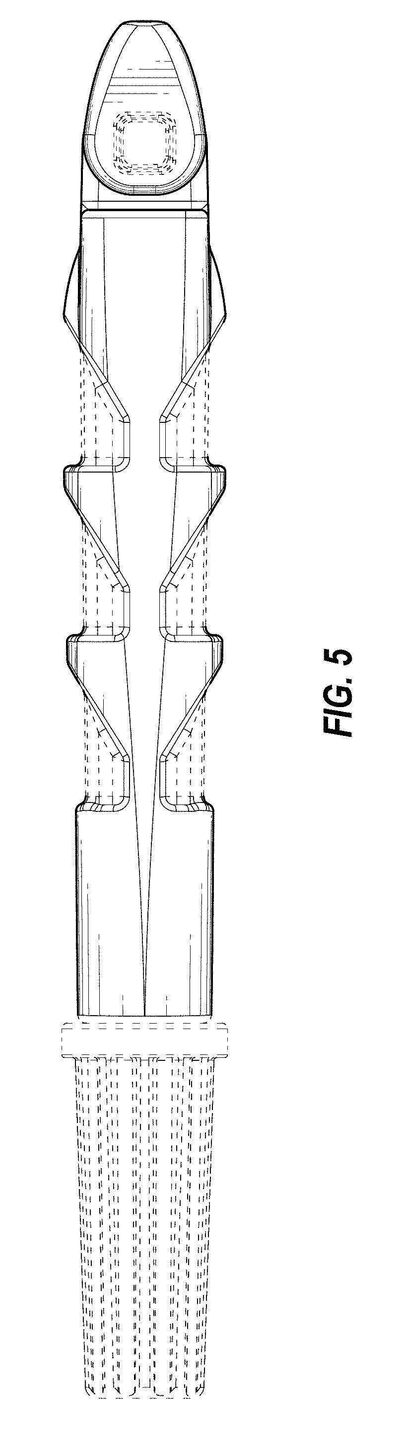
FIG. 5 is a right side view of the dental matrix device of FIG. 1;
FIG. 6 is a left side view of the dental matrix device of FIG. 1; and,
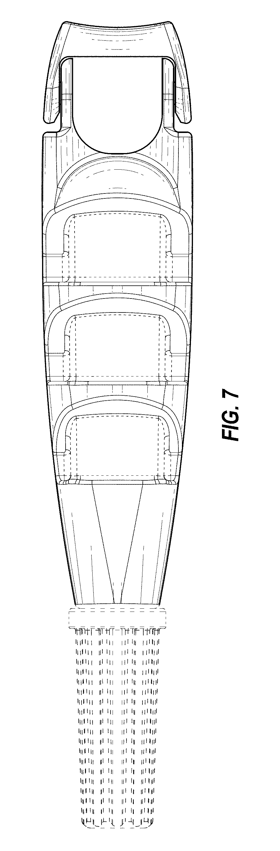
FIG. 7 is a top view of the dental matrix device of FIG. 1, which is identical to a bottom view of the dental matrix device of FIG. 1.
In the drawings, the broken lines depict environmental subject matter only and form no part of the claimed design.
* * * * *
D00000
D00001
D00002
D00003
D00004
D00005
D00006
XML
uspto.report is an independent third-party trademark research tool that is not affiliated, endorsed, or sponsored by the United States Patent and Trademark Office (USPTO) or any other governmental organization. The information provided by uspto.report is based on publicly available data at the time of writing and is intended for informational purposes only.
While we strive to provide accurate and up-to-date information, we do not guarantee the accuracy, completeness, reliability, or suitability of the information displayed on this site. The use of this site is at your own risk. Any reliance you place on such information is therefore strictly at your own risk.
All official trademark data, including owner information, should be verified by visiting the official USPTO website at www.uspto.gov. This site is not intended to replace professional legal advice and should not be used as a substitute for consulting with a legal professional who is knowledgeable about trademark law.