Passenger carrying car
Takahashi , et al. Sept
U.S. patent number D860,049 [Application Number D/547,843] was granted by the patent office on 2019-09-17 for passenger carrying car. This patent grant is currently assigned to CENTRAL JAPAN RAILWAY COMPANY, NIPPON SHARYO, LTD.. The grantee listed for this patent is CENTRAL JAPAN RAILWAY COMPANY, NIPPON SHARYO, LTD.. Invention is credited to Yuya Futamura, Koichi Hayashi, Naoyuki Maruyama, Naoya Ozawa, Yukio Takahashi, Hiroki Tanaka.


View All Diagrams
| United States Patent | D860,049 |
| Takahashi , et al. | September 17, 2019 |
Passenger carrying car
Claims
CLAIM The ornamental design for a passenger carrying car, as shown and described.
| Inventors: | Takahashi; Yukio (Nagoya, JP), Futamura; Yuya (Nagoya, JP), Hayashi; Koichi (Nagoya, JP), Tanaka; Hiroki (Nagoya, JP), Ozawa; Naoya (Nagoya, JP), Maruyama; Naoyuki (Nagoya, JP) | ||||||||||
|---|---|---|---|---|---|---|---|---|---|---|---|
| Applicant: |
|
||||||||||
| Assignee: | CENTRAL JAPAN RAILWAY COMPANY
(Nagoya, JP) NIPPON SHARYO, LTD. (Nagoya, JP) |
||||||||||
| Appl. No.: | D/547,843 | ||||||||||
| Filed: | December 8, 2015 |
Related U.S. Patent Documents
| Application Number | Filing Date | Patent Number | Issue Date | ||
|---|---|---|---|---|---|
| 29455473 | May 21, 2013 | D757605 | |||
Foreign Application Priority Data
| Nov 21, 2012 [JP] | 2012-028580 | |||
| Nov 21, 2012 [JP] | 2012-028582 | |||
| Nov 21, 2012 [JP] | 2012-028583 | |||
| Nov 21, 2012 [JP] | 2012-028584 | |||
| Nov 21, 2012 [JP] | 2012-028585 | |||
| Current U.S. Class: | D12/42 |
| Current International Class: | 1203 |
| Field of Search: | ;D12/36-51,320,195,345,99 ;D11/155 ;D5/63 ;181/290 ;105/404,396,397 ;D25/168-164,58 |
References Cited [Referenced By]
U.S. Patent Documents
| D118272 | December 1939 | Verhagen |
| 2217688 | October 1940 | Larson |
| D128507 | July 1941 | Stewart |
| 2284356 | May 1942 | Arenberg |
| D146982 | June 1947 | Phillips |
| 2494690 | January 1950 | Cerny |
| 2882836 | April 1959 | Dean |
| 2887802 | May 1959 | Burmeister |
| 2925050 | February 1960 | Candlin, Jr. |
| 3046179 | July 1962 | Stallard |
| D209877 | January 1968 | Sundberg |
| 4993329 | February 1991 | Takeich et al. |
| D437810 | February 2001 | Runfola |
| D721445 | January 2015 | Kugler |
| 2006/0219716 | October 2006 | Todori |
| 2015/0314794 | November 2015 | Takahashi |
Other References
|
Oct. 4, 2018 Office Action issued in U.S. Appl. No. 29/547,850. cited by applicant . Apr. 19, 2019 Office Action issued in U.S. Appl. No. 29/547,850. cited by applicant. |
Primary Examiner: Nelson; T Chase
Assistant Examiner: Aman; Ania
Attorney, Agent or Firm: Oliff PLC
Description
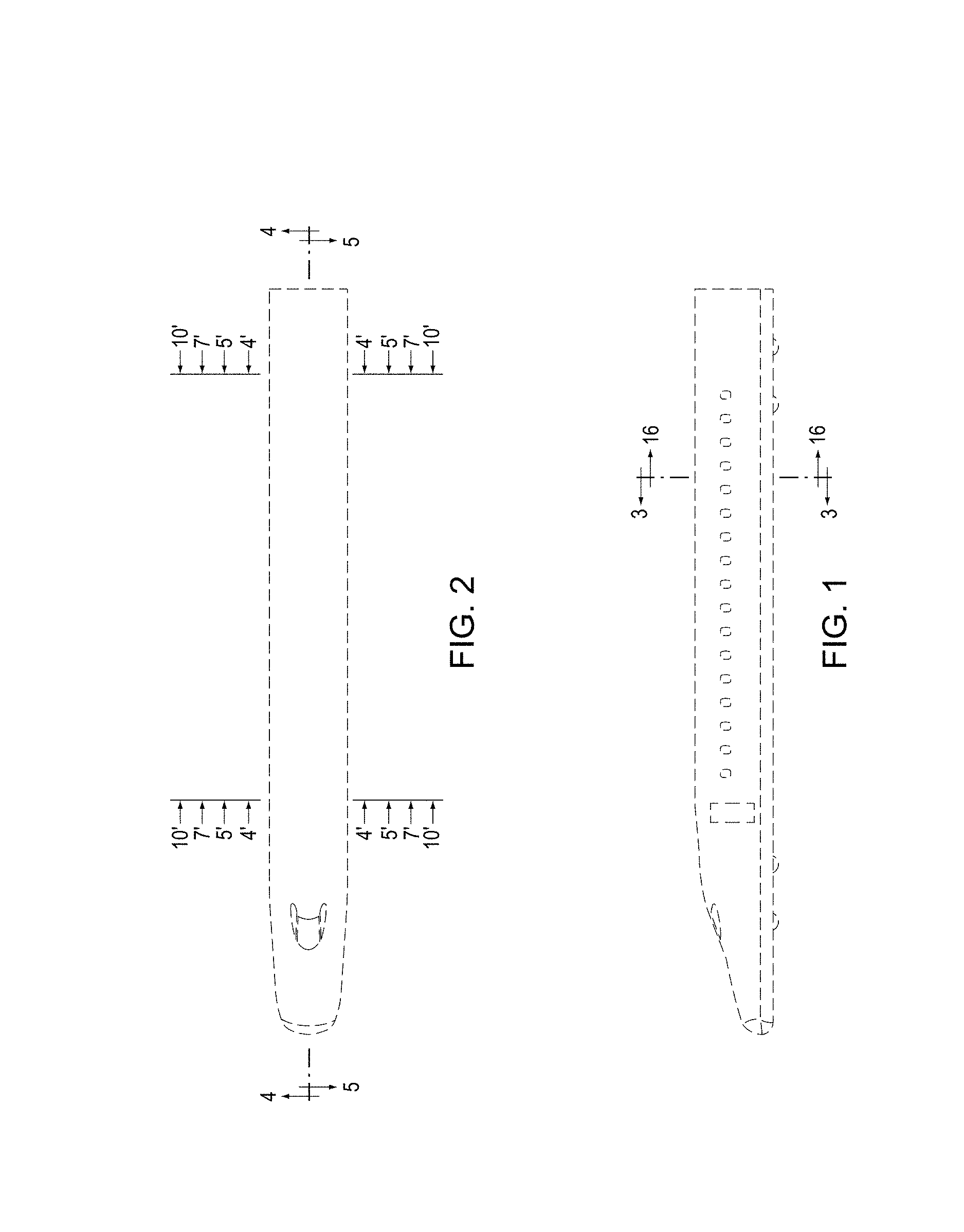
FIG. 1 is a side view of a passenger carrying car;
FIG. 2 is a top view thereof;
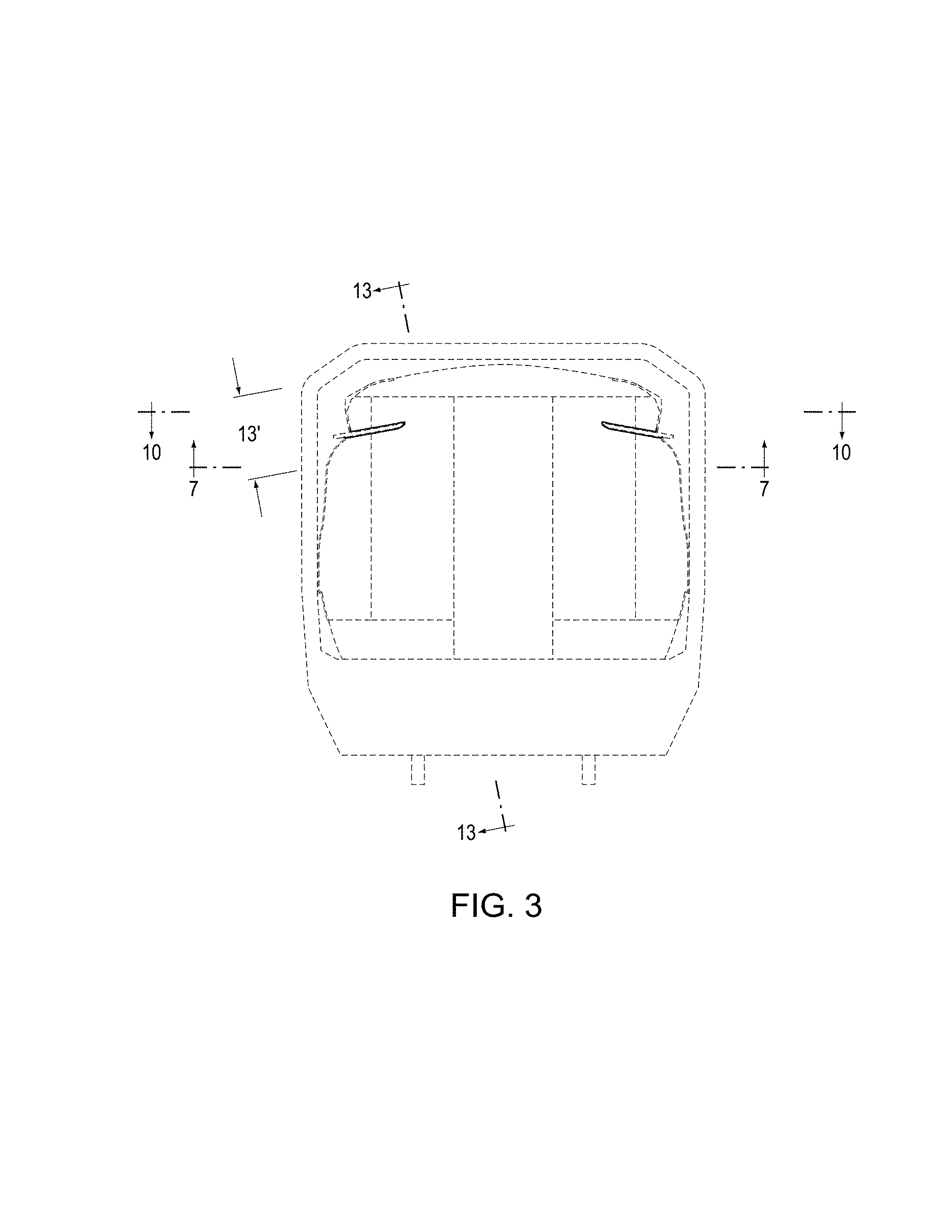
FIG. 3 is an enlarged cross sectional view thereof taken along lines 3-3 in FIG. 1;
FIG. 4 is a partially enlarged view thereof defined by the areas 4' in FIG. 2 and taken along the lines 4-4 in FIG. 2;
FIG. 5 is a partially enlarged view thereof defined by the areas 5' in FIG. 2 and taken along the lines 5-5 in FIG. 2;
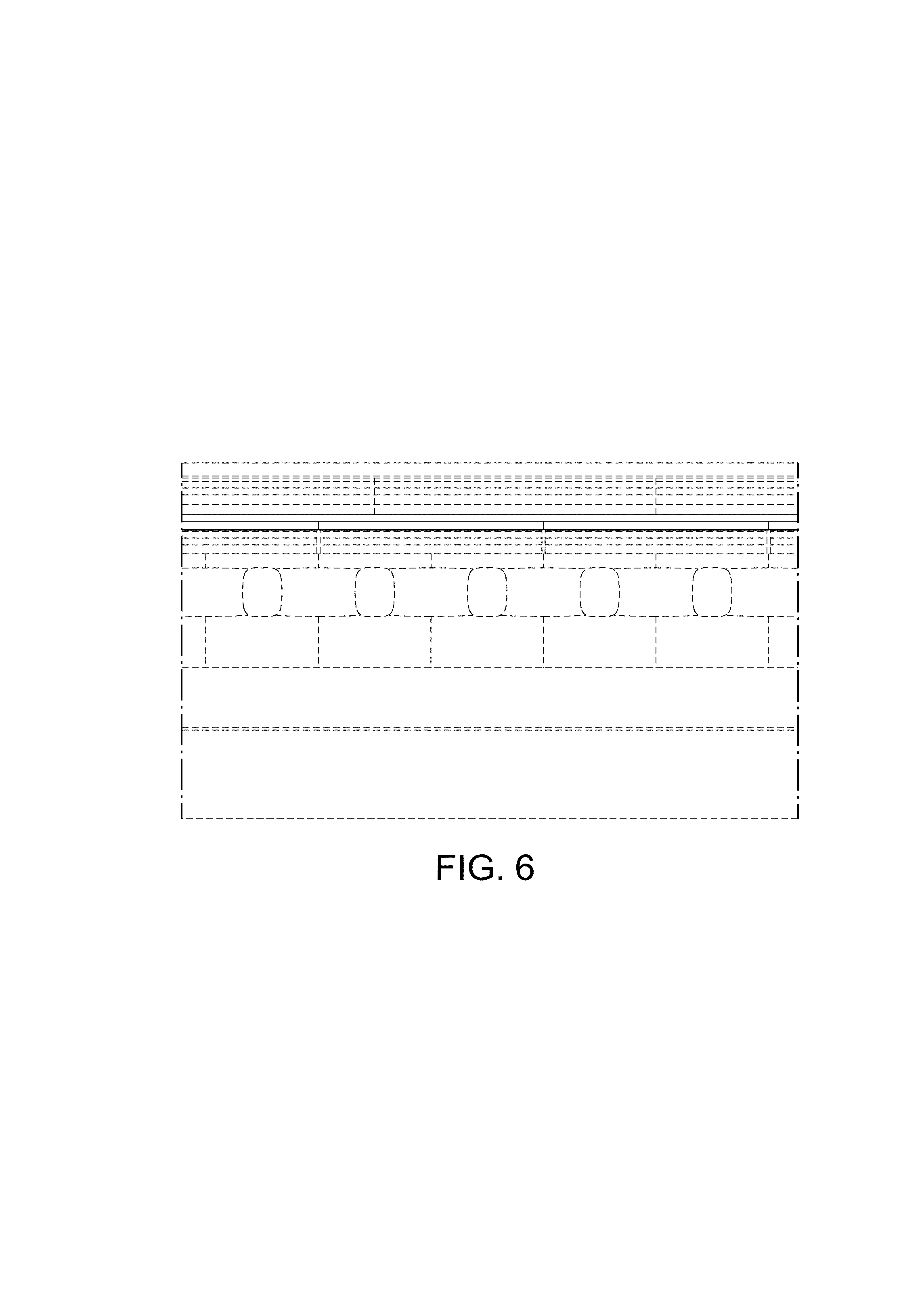
FIG. 6 is a partially enlarged cross sectional view thereof defined by the area 6' in FIG. 4;
FIG. 7 is a partially enlarged cross sectional view thereof defined by the area 7' in FIG. 2 and taken along the lines 7-7 in FIG. 3;
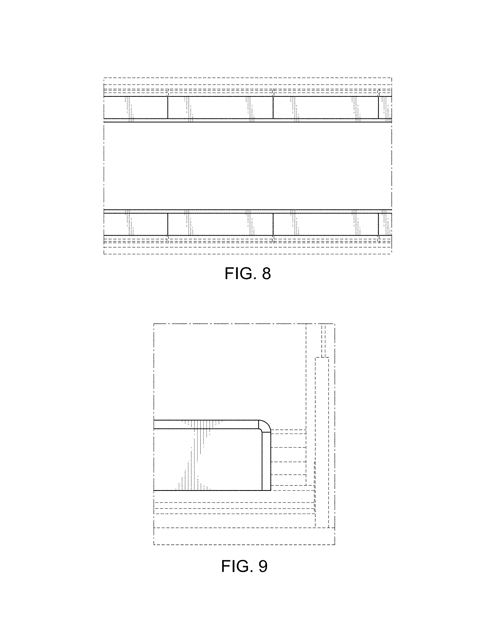
FIG. 8 is a partially enlarged cross sectional view thereof defined by the area 8' in FIG. 7;
FIG. 9 is a partially enlarged view thereof defined by the broken line box 9 in FIG. 7;
FIG. 10 is a partially enlarged cross sectional view thereof defined by the area 10' in FIG. 2 and taken along the lines 10-10 in FIG. 3;
FIG. 11 is a partially enlarged cross sectional view thereof defined by the area 11' in FIG. 10;
FIG. 12 is a partially enlarged view thereof defined by the broken line box 12 in FIG. 10;
FIG. 13 is a partially enlarged cross sectional view thereof defined by the area 13' in FIG. 3 and taken along the lines 13-13 in FIG. 3;
FIG. 14 is a partially enlarged cross sectional view thereof defined by the area 14' in FIG. 13;
FIG. 15 is a partially enlarged view thereof defined by the broken line box 15 in FIG. 13;
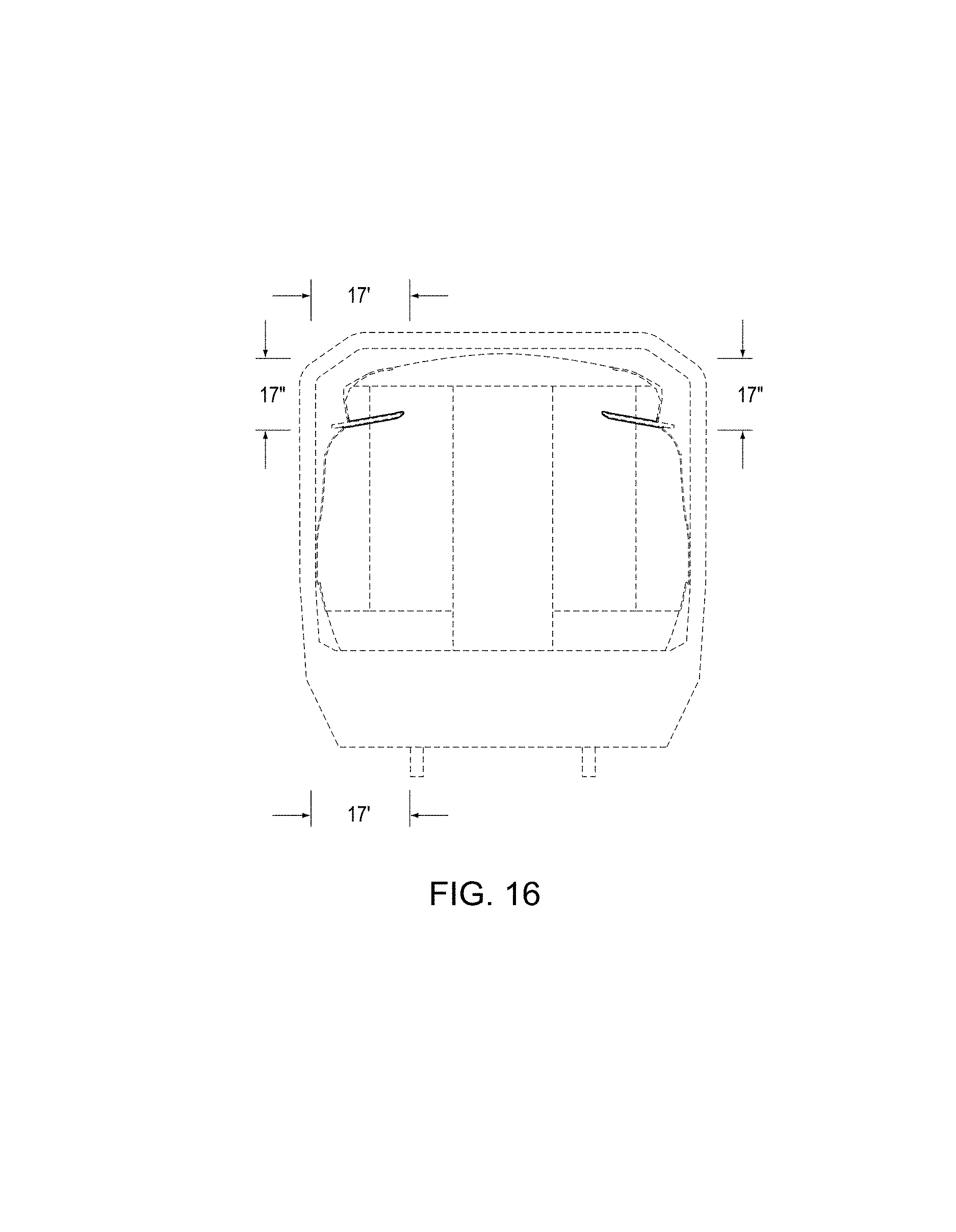
FIG. 16 is another partially enlarged cross sectional view thereof taken along lines 16-16 in FIG. 1; and,
FIG. 17 is a partially enlarged cross sectional view thereof defined by the areas 17' and 17'' in FIG. 16 and taken along the lines 17-17 in FIG. 13.
The broken lines depict environmental subject matter only and form no part of the claimed design.
* * * * *
D00000
D00001
D00002
D00003
D00004
D00005
D00006
D00007
D00008
D00009
D00010
D00011
XML
uspto.report is an independent third-party trademark research tool that is not affiliated, endorsed, or sponsored by the United States Patent and Trademark Office (USPTO) or any other governmental organization. The information provided by uspto.report is based on publicly available data at the time of writing and is intended for informational purposes only.
While we strive to provide accurate and up-to-date information, we do not guarantee the accuracy, completeness, reliability, or suitability of the information displayed on this site. The use of this site is at your own risk. Any reliance you place on such information is therefore strictly at your own risk.
All official trademark data, including owner information, should be verified by visiting the official USPTO website at www.uspto.gov. This site is not intended to replace professional legal advice and should not be used as a substitute for consulting with a legal professional who is knowledgeable about trademark law.