Tint meter device having a slot for self-positioning of the tint meter onto a glass edge
Simpson , et al. A
U.S. patent number D856,830 [Application Number D/645,433] was granted by the patent office on 2019-08-20 for tint meter device having a slot for self-positioning of the tint meter onto a glass edge. This patent grant is currently assigned to EDTM, Inc.. The grantee listed for this patent is EDTM, Inc.. Invention is credited to Mark A. Imbrock, Jeffrey A. Simpson.


View All Diagrams
| United States Patent | D856,830 |
| Simpson , et al. | August 20, 2019 |
Tint meter device having a slot for self-positioning of the tint meter onto a glass edge
Claims
CLAIM The ornamental designs for a tint meter device having a slot for self-positioning of the tint meter onto a glass edge, as shown and described.
| Inventors: | Simpson; Jeffrey A. (Wayne, NE), Imbrock; Mark A. (Sylvania, OH) | ||||||||||
|---|---|---|---|---|---|---|---|---|---|---|---|
| Applicant: |
|
||||||||||
| Assignee: | EDTM, Inc. (Toledo,
OH) |
||||||||||
| Appl. No.: | D/645,433 | ||||||||||
| Filed: | April 26, 2018 |
| Current U.S. Class: | D10/78 |
| Current International Class: | 1004 |
| Field of Search: | ;D10/78,81 |
References Cited [Referenced By]
U.S. Patent Documents
| 4037972 | July 1977 | Pross |
| 5197910 | March 1993 | Kanno |
| D362810 | October 1995 | Seaburn |
| D782927 | April 2017 | Nothacker |
| D796977 | September 2017 | Yokoyama |
Attorney, Agent or Firm: MacMillan, Sobanski & Todd, LLC
Description
FIG. 1 is a perspective front elevational view of a tint meter device having a slot for self-positioning of the tint meter onto a glass edge according to a first embodiment;
FIG. 2 is a front elevational view of the first embodiment;
FIG. 3 is a rear elevational view of the first embodiment;
FIG. 4 is a left side elevational of the first embodiment;
FIG. 5 is a right side elevational view of the first embodiment;
FIG. 6 is a top plan view of the first embodiment;
FIG. 7 is a bottom plan view of the first embodiment;
FIG. 8 is a front elevational view of a tint meter device having a slot for self-positioning of the tint meter onto a glass edge according to a second embodiment, where the left side, right side, top plan and bottom plan views are the same as for the first embodiment;
FIG. 9 is a rear elevational view of the second embodiment;
FIG. 10 is a front elevational view of a tint meter device having a slot for self-positioning of the tint meter onto a glass edge according to a third embodiment, where the left side, right side, top plan and bottom plan views are the same as for the first embodiment;
FIG. 11 is a rear elevational view of the third embodiment;
FIG. 12 is a front elevational view of a tint meter device having a slot for self-positioning of the tint meter onto a glass edge according to a fourth embodiment, where the left side, right side, top plan and bottom plan views are the same as for the first embodiment;
FIG. 13 is a rear elevational view of the fourth embodiment;
FIG. 14 is a front elevational view of a tint meter device having a slot for self-positioning of the tint meter onto a glass edge according to a fifth embodiment, where the left side, right side, top plan and bottom plan views are the same as for the first embodiment;
FIG. 15 is a rear elevational view of the fifth embodiment;
FIG. 16 is a front elevational view of a tint meter device having a slot for self-positioning of the tint meter onto a glass edge according to a sixth embodiment, where the left side, right side, top plan and bottom plan views are the same as for the first embodiment;
FIG. 17 is a rear elevational view of the fifth embodiment;
FIG. 18 is a front elevational view of a tint meter device having a slot for self-positioning of the tint meter onto a glass edge according to a seventh embodiment, where the left side, right side, top plan and bottom plan views are the same as for the first embodiment;
FIG. 19 is a rear elevational view of the seventh embodiment;
FIG. 20 is a front elevational view of a tint meter device having a slot for self-positioning of the tint meter onto a glass edge according to an eighth embodiment, where the left side, right side, top plan and bottom plan views are the same as for the first embodiment;
FIG. 21 is a rear elevational view of the eighth embodiment;
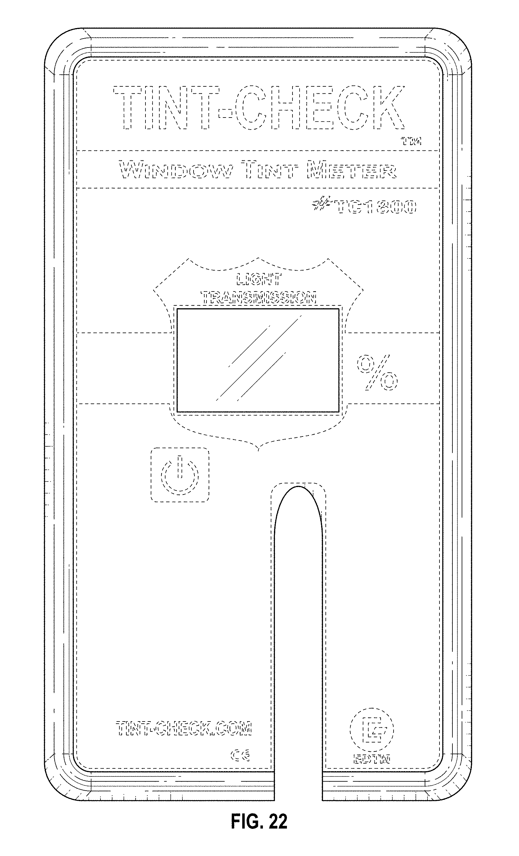
FIG. 22 is a front elevational view of a tint meter device having a slot for self-positioning of the tint meter onto a glass edge according to a ninth embodiment, where the left side, right side, top plan and bottom plan views are the same as for the first embodiment;
FIG. 23 is a rear elevational view of the ninth embodiment;
FIG. 24 is a front elevational view of a tint meter device having a slot for self-positioning of the tint meter onto a glass edge according to a tenth embodiment, where the left side, right side, top plan and bottom plan views are the same as for the first embodiment;
FIG. 25 is a rear elevational view of the tenth embodiment;
FIG. 26 is a front elevational view of a tint meter device having a slot for self-positioning of the tint meter onto a glass edge according to a eleventh embodiment, where the left side, right side, top plan and bottom plan views are the same as for the first embodiment;
FIG. 27 is a rear elevational view of the eleventh embodiment;
FIG. 28 is a front elevational view of a tint meter device having a slot for self-positioning of the tint meter onto a glass edge according to a twelfth embodiment, where the left side, right side, top plan and bottom plan views are the same as for the first embodiment;
FIG. 29 is a rear elevational view of the twelfth embodiment;
FIG. 30 is a front elevational view of a tint meter device having a slot for self-positioning of the tint meter onto a glass edge according to a thirteenth embodiment, where the left side, right side, top plan and bottom plan views are the same as for the first embodiment; and,
FIG. 31 is a rear elevational view of the thirteenth embodiment.
The broken lines in the Figures are included for the purpose of illustrating portions of the embodiments that form no part of the claimed design.
* * * * *
D00000
D00001
D00002
D00003
D00004
D00005
D00006
D00007
D00008
D00009
D00010
D00011
D00012

D00013

D00014

D00015

D00016

D00017

D00018

D00019

D00020
D00021

D00022

D00023

D00024

D00025

D00026

D00027

D00028

D00029

XML
uspto.report is an independent third-party trademark research tool that is not affiliated, endorsed, or sponsored by the United States Patent and Trademark Office (USPTO) or any other governmental organization. The information provided by uspto.report is based on publicly available data at the time of writing and is intended for informational purposes only.
While we strive to provide accurate and up-to-date information, we do not guarantee the accuracy, completeness, reliability, or suitability of the information displayed on this site. The use of this site is at your own risk. Any reliance you place on such information is therefore strictly at your own risk.
All official trademark data, including owner information, should be verified by visiting the official USPTO website at www.uspto.gov. This site is not intended to replace professional legal advice and should not be used as a substitute for consulting with a legal professional who is knowledgeable about trademark law.