Digital level
Wojciechowski , et al. A
U.S. patent number D856,173 [Application Number D/623,143] was granted by the patent office on 2019-08-13 for digital level. This patent grant is currently assigned to Diamond Tech LLC. The grantee listed for this patent is Diamond Tech LLC. Invention is credited to David Mencel, Timothy J. Wojciechowski.


View All Diagrams
| United States Patent | D856,173 |
| Wojciechowski , et al. | August 13, 2019 |
| **Please see images for: ( Certificate of Correction ) ** |
Digital level
Claims
CLAIM The ornamental design of a digital level, as shown and described.
| Inventors: | Wojciechowski; Timothy J. (Hubertus, WI), Mencel; David (Menomonee Falls, WI) | ||||||||||
|---|---|---|---|---|---|---|---|---|---|---|---|
| Applicant: |
|
||||||||||
| Assignee: | Diamond Tech LLC (Carson City,
NV) |
||||||||||
| Appl. No.: | D/623,143 | ||||||||||
| Filed: | October 23, 2017 |
| Current U.S. Class: | D10/69 |
| Current International Class: | 1004 |
| Field of Search: | ;D10/69 |
References Cited [Referenced By]
U.S. Patent Documents
| D364104 | November 1995 | Johnson |
| D521399 | May 2006 | Johnson et al. |
| D535576 | January 2007 | Schafer et al. |
| D555523 | November 2007 | Nickel et al. |
| D633400 | March 2011 | Wojciechowski et al. |
| D634221 | March 2011 | Wojciechowski et al. |
| D656425 | March 2012 | Wojciechowski et al. |
| 8925212 | January 2015 | Allemand |
| D735064 | July 2015 | Wojciechowski et al. |
| D735065 | July 2015 | Wojciechowski et al. |
| 9909870 | March 2018 | Neitzell |
| 10001371 | June 2018 | Neitzell |
| D825353 | August 2018 | Wojciechowski |
| D825354 | August 2018 | Wojciechowski |
Attorney, Agent or Firm: Boyle Fredrickson, S.C.
Description
FIG. 1 is an isometric view of a first embodiment of a digital level incorporating our new design:
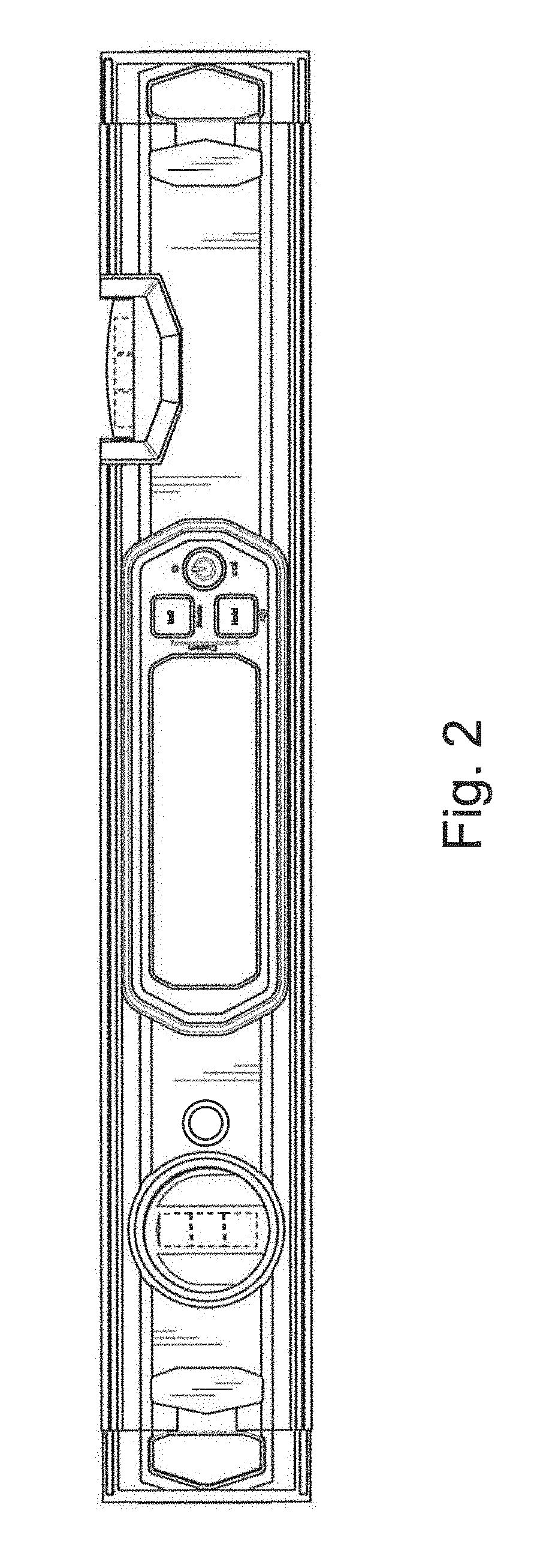
FIG. 2 is a front elevation view thereof;
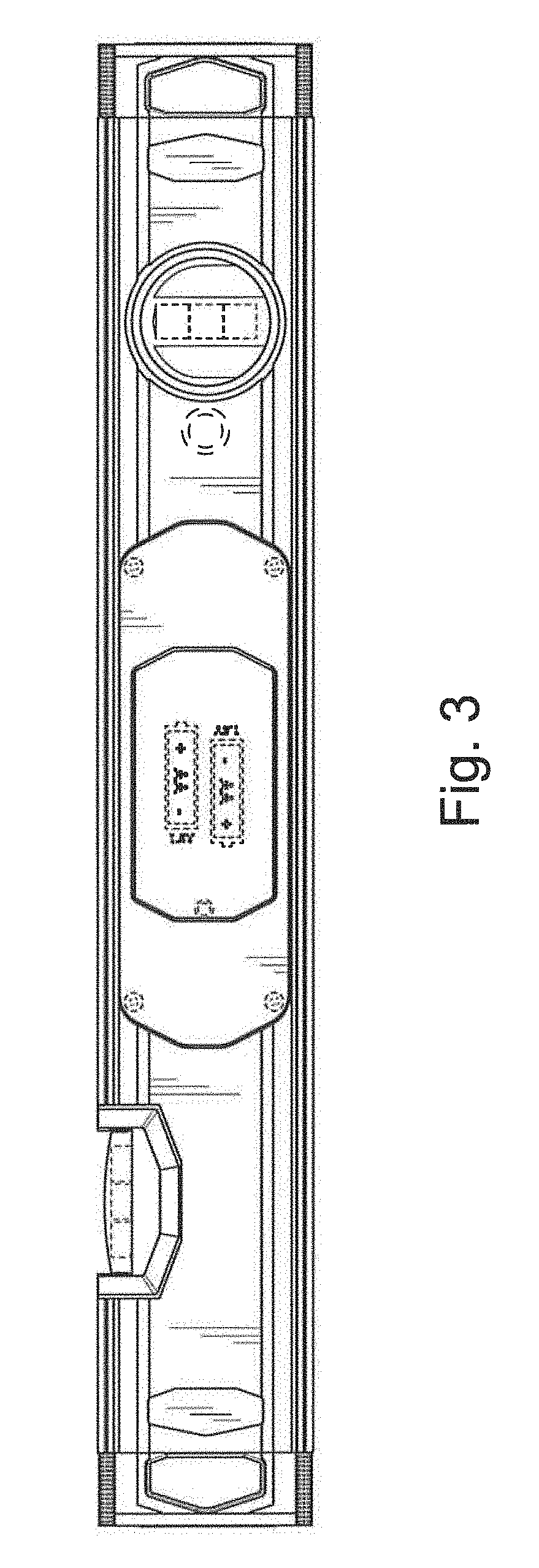
FIG. 3 is a rear elevation view thereof;
FIG. 4 is a top plan view thereof;
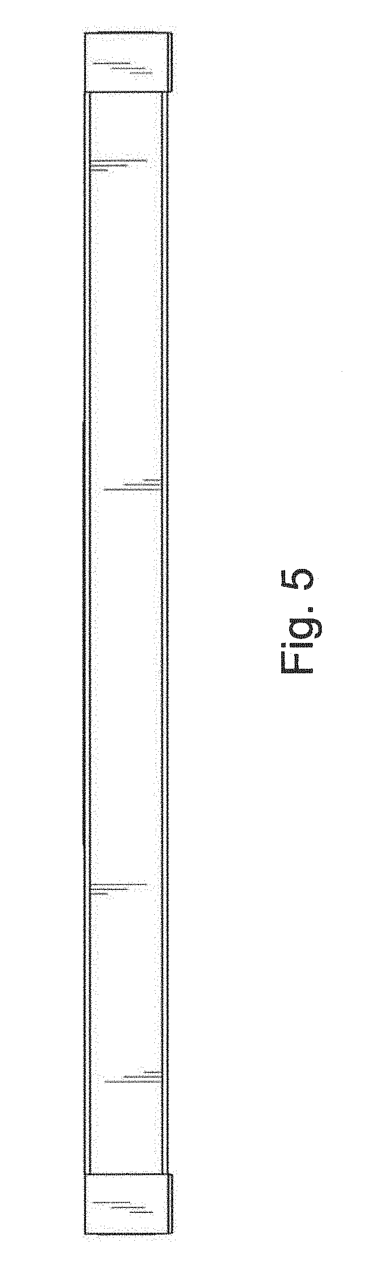
FIG. 5 is a bottom plan view thereof;
FIG. 6 is a first end elevation view thereof;
FIG. 7 is a second end elevation view thereof;
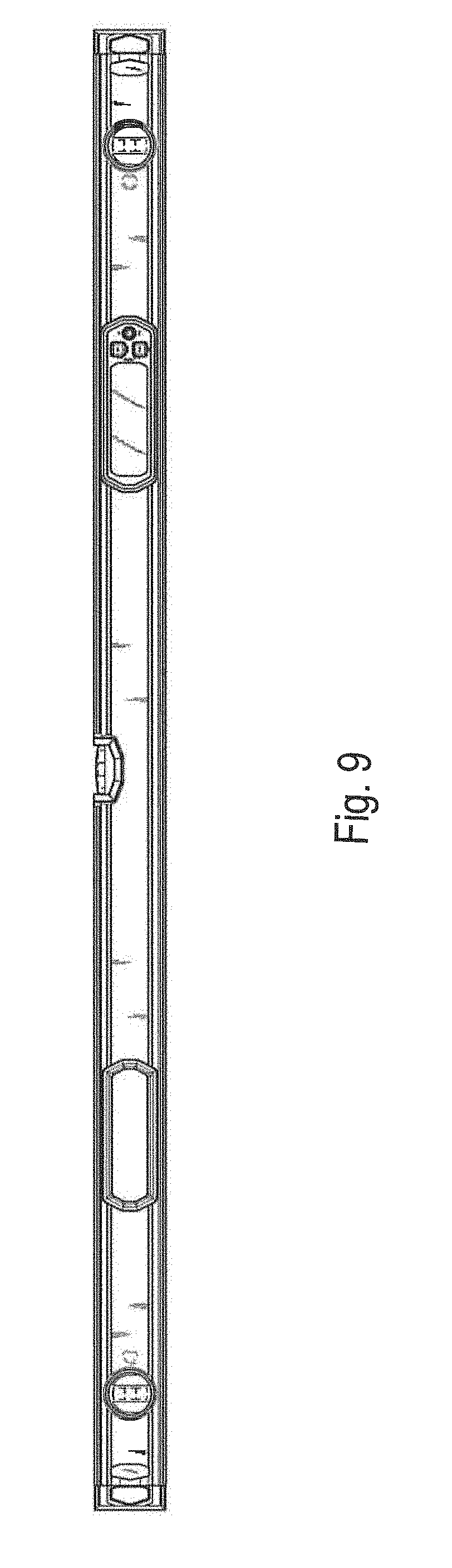
FIG. 8 is an isometric view of a third embodiment of a digital level incorporating our new design, wherein the end elevation views are identical to those shown in FIGS. 6 and 7:
FIG. 9 is a front elevation view thereof;
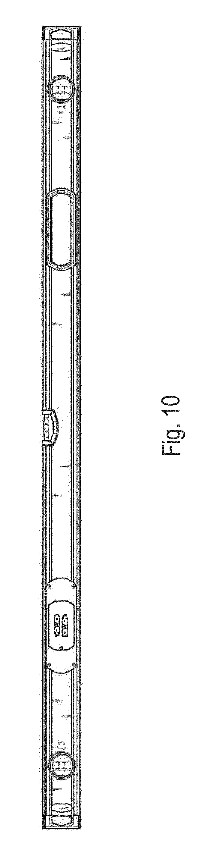
FIG. 10 is a rear elevation view thereof;
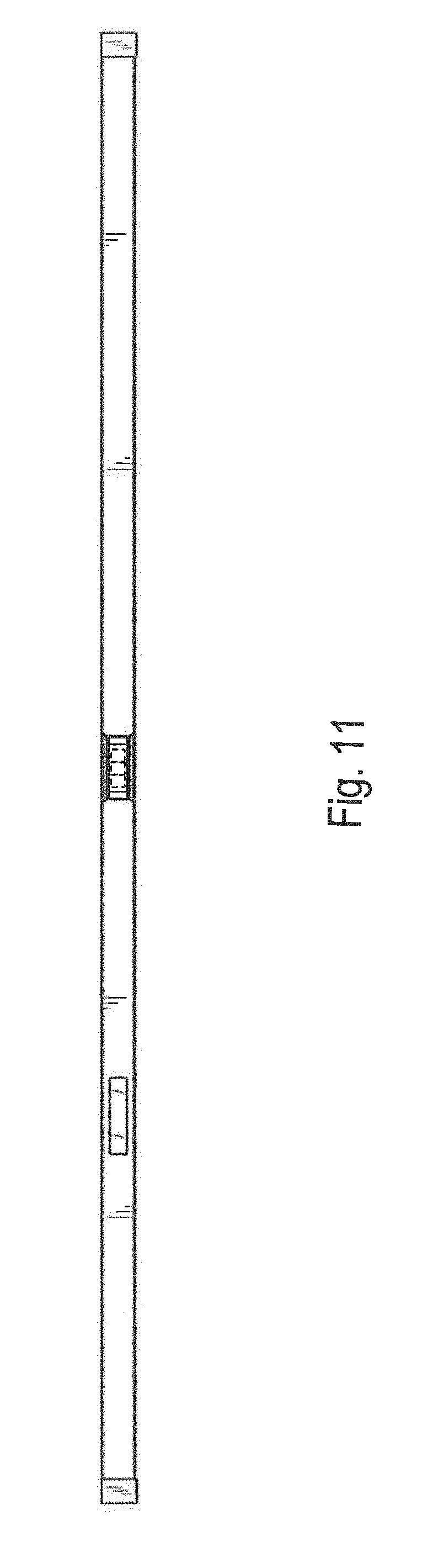
FIG. 11 is a top plan view thereof;
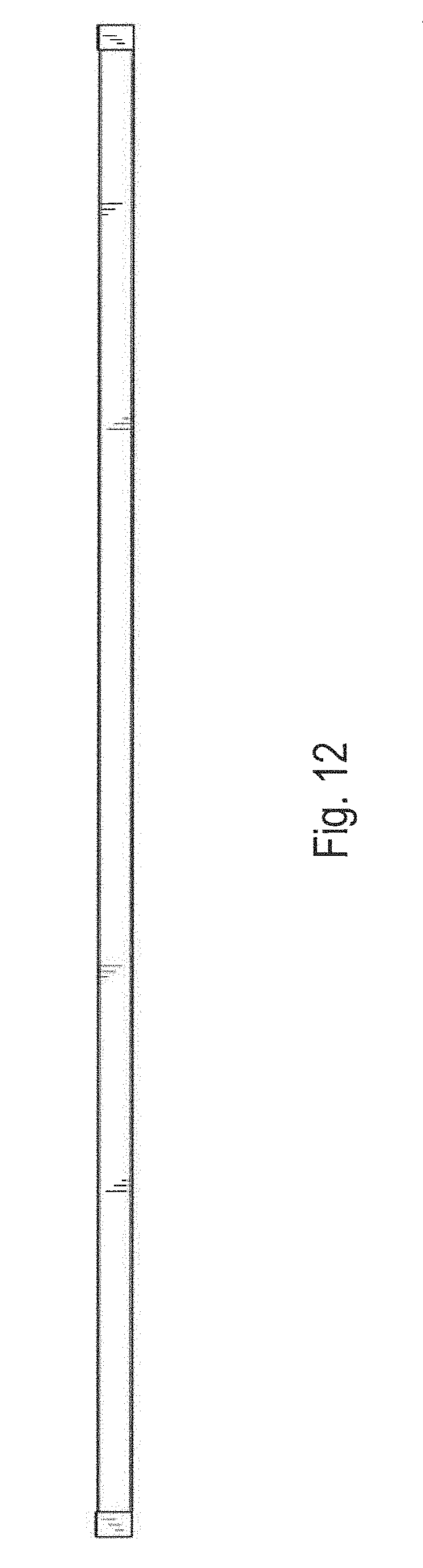
FIG. 12 is a bottom plan view thereof;
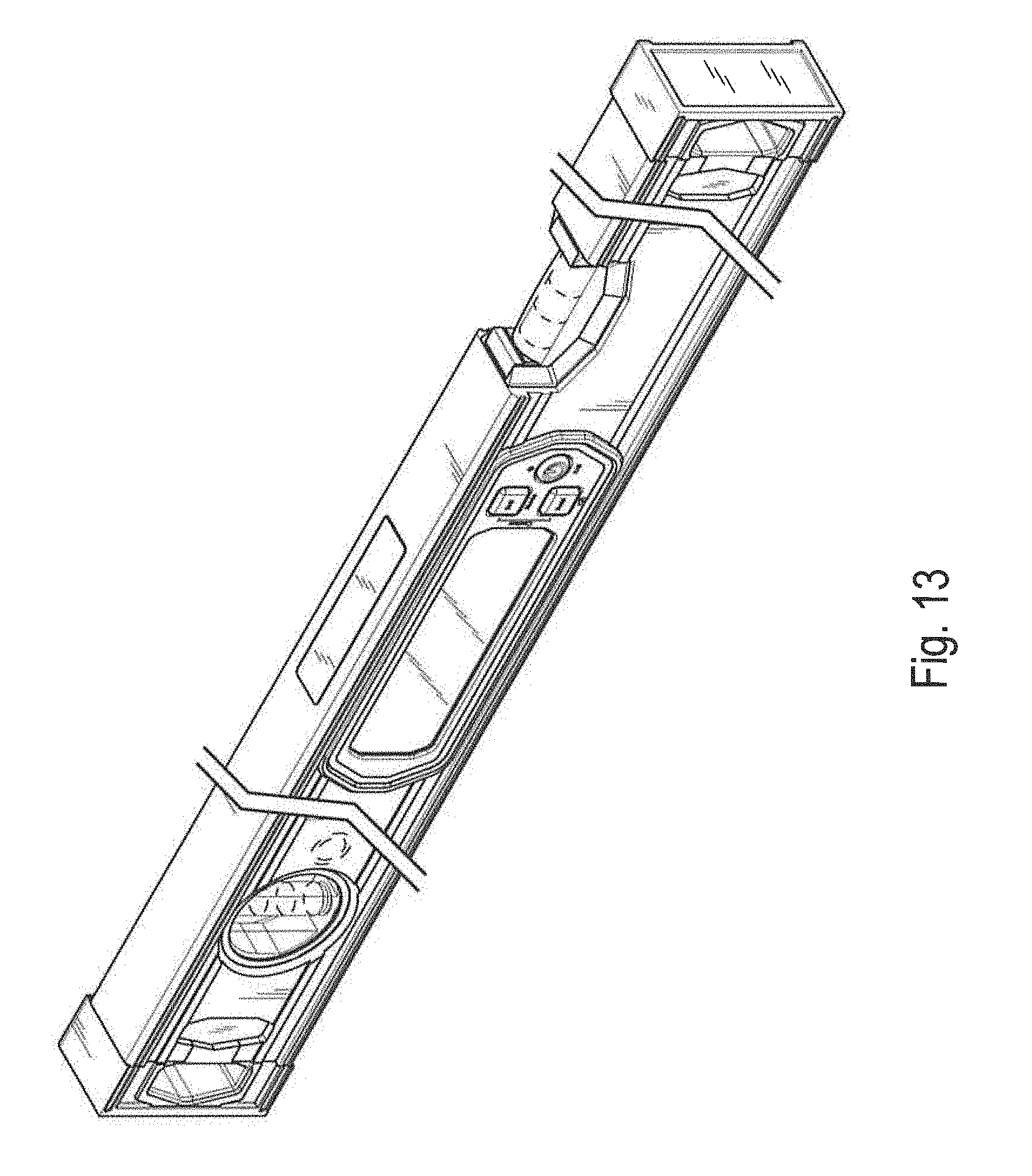
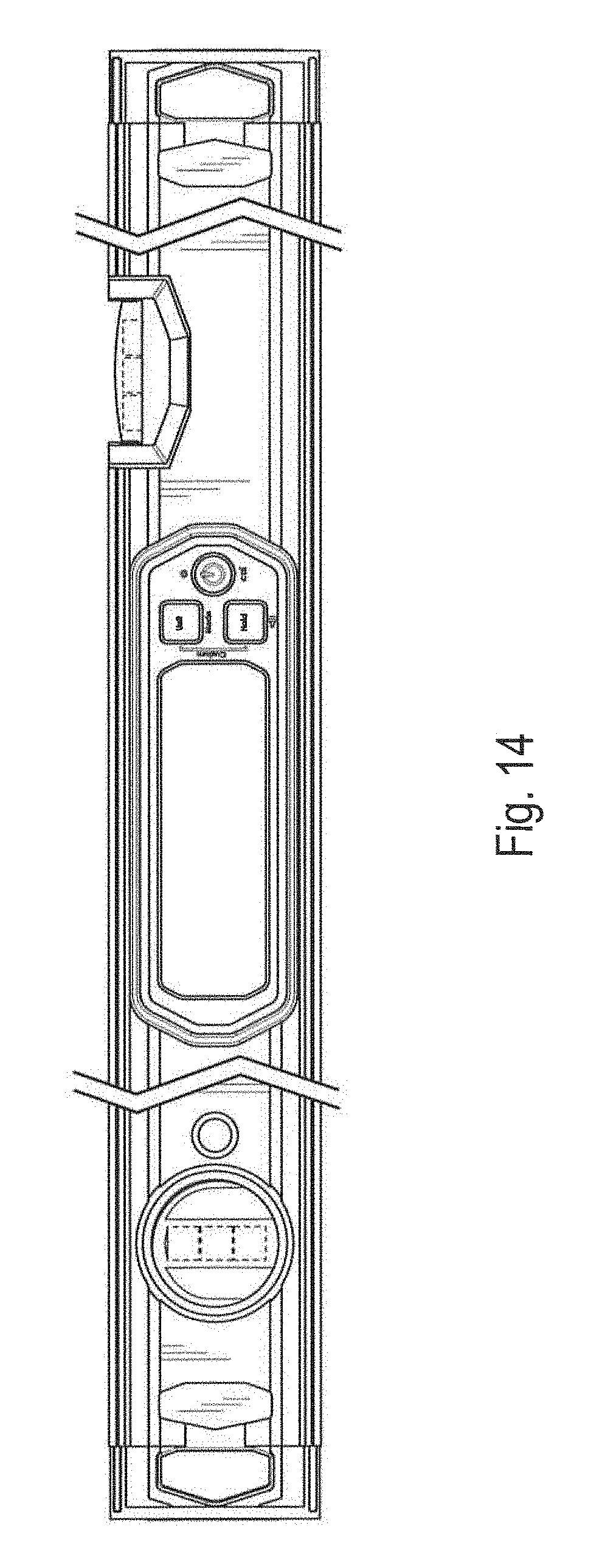
FIG. 13 is an isometric view of an embodiment of a digital level incorporating our new design, with break lines illustrating indeterminate length, and wherein the end elevation views are identical to those shown in FIGS. 6 and 7:
FIG. 14 is a front elevation view thereof;
FIG. 15 is a rear elevation view thereof;
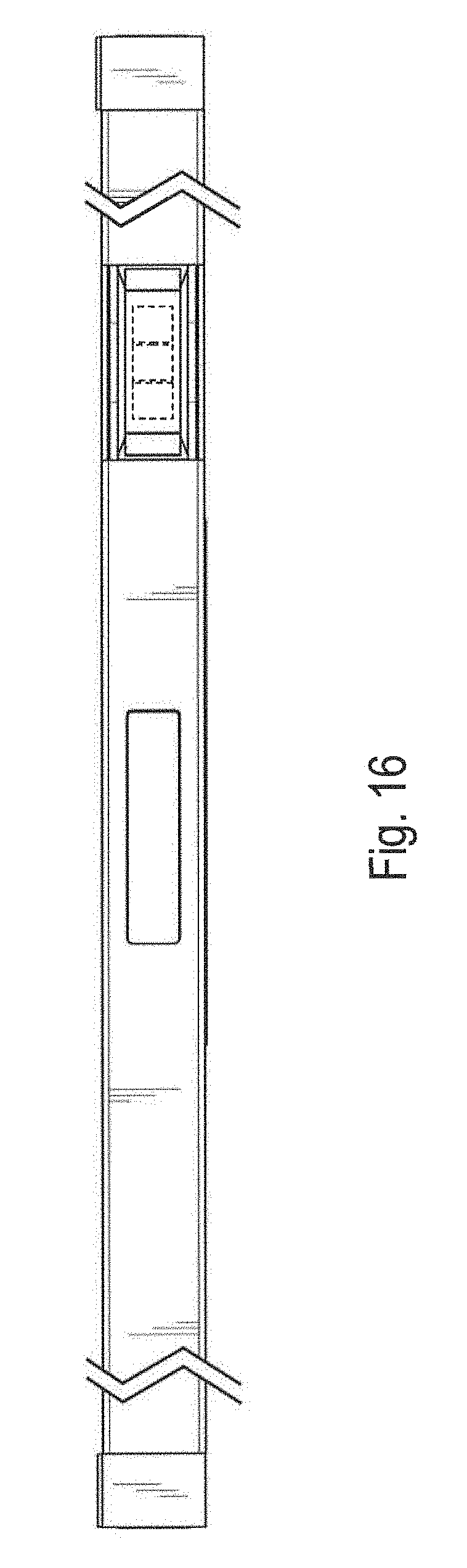
FIG. 16 is a top plan view thereof; and,
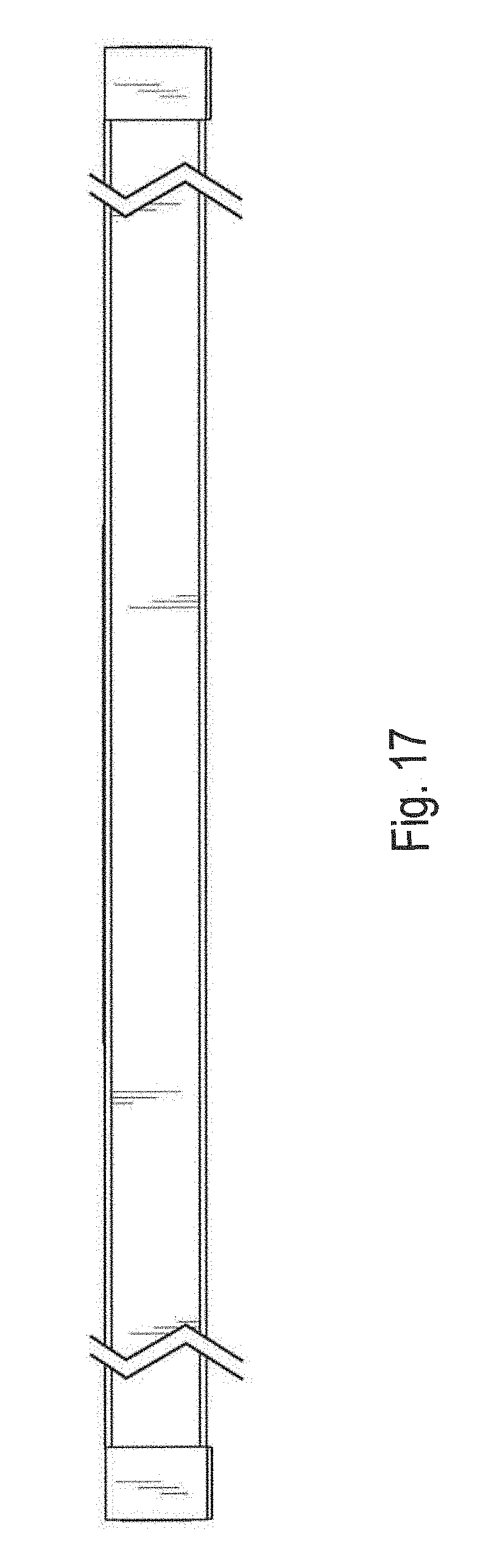
FIG. 17 is a bottom plan view thereof.
* * * * *
D00000
D00001
D00002
D00003
D00004
D00005
D00006
D00007
D00008
D00009
D00010
D00011
D00012
D00013
D00014

D00015
D00016
XML
uspto.report is an independent third-party trademark research tool that is not affiliated, endorsed, or sponsored by the United States Patent and Trademark Office (USPTO) or any other governmental organization. The information provided by uspto.report is based on publicly available data at the time of writing and is intended for informational purposes only.
While we strive to provide accurate and up-to-date information, we do not guarantee the accuracy, completeness, reliability, or suitability of the information displayed on this site. The use of this site is at your own risk. Any reliance you place on such information is therefore strictly at your own risk.
All official trademark data, including owner information, should be verified by visiting the official USPTO website at www.uspto.gov. This site is not intended to replace professional legal advice and should not be used as a substitute for consulting with a legal professional who is knowledgeable about trademark law.