Handle
Hall , et al.
U.S. patent number D855,435 [Application Number D/617,876] was granted by the patent office on 2019-08-06 for handle. This patent grant is currently assigned to Whirlpool Corporation. The grantee listed for this patent is WHIRLPOOL CORPORATION. Invention is credited to John A. Hall, Zachary A. Lownds, Michael S. Seeley, Jason W. Tippetts, Rex Wilson, ZhaoYi Yin.


View All Diagrams
| United States Patent | D855,435 |
| Hall , et al. | August 6, 2019 |
Handle
Claims
CLAIM We claim the ornamental design for a handle, as shown and described.
| Inventors: | Hall; John A. (Holland, MI), Lownds; Zachary A. (St. Joseph, MI), Seeley; Michael S. (South Haven, MI), Tippetts; Jason W. (Stevensville, MI), Wilson; Rex (St. Joseph, MI), Yin; ZhaoYi (Benton Harbor, MI) | ||||||||||
|---|---|---|---|---|---|---|---|---|---|---|---|
| Applicant: |
|
||||||||||
| Assignee: | Whirlpool Corporation (Benton
Harbor, MI) |
||||||||||
| Appl. No.: | D/617,876 | ||||||||||
| Filed: | September 15, 2017 |
| Current U.S. Class: | D8/313 |
| Current International Class: | 0806 |
| Field of Search: | ;D8/301,302,313,315,316,318,319,320,331 ;D7/393,394 |
References Cited [Referenced By]
U.S. Patent Documents
| 2616122 | November 1952 | Curtiss, Jr. |
| D190226 | May 1961 | Watt |
| D190266 | May 1961 | Watt |
| D206152 | November 1966 | Morgan |
| D219619 | December 1970 | Young |
| D266122 | September 1982 | Haug |
| 4586762 | May 1986 | Kennedy |
| 4732430 | March 1988 | Byrns |
| 4744126 | May 1988 | Bisbing |
| D316357 | April 1991 | Chanda |
| D370617 | June 1996 | Decursu et al. |
| D400424 | November 1998 | Lewis et al. |
| 5921648 | July 1999 | Rong |
| D424873 | May 2000 | Holbrook |
| D435779 | January 2001 | Marzolf |
| D449215 | October 2001 | Bertani |
| D450212 | November 2001 | Gottwald |
| D471403 | March 2003 | Jones et al. |
| D488699 | April 2004 | Jackovin |
| D511955 | November 2005 | Baldwin et al. |
| D513694 | January 2006 | Vitkauskas |
| D524103 | July 2006 | Bradshaw |
| D542090 | May 2007 | Kim |
| D562668 | February 2008 | Stuckey |
| D564331 | March 2008 | Borgonovo |
| D568100 | May 2008 | Jeon |
| D570666 | June 2008 | Samhammer |
| D571633 | June 2008 | Shuman |
| D572110 | July 2008 | Busalt et al. |
| D576607 | September 2008 | Barrios |
| D577567 | September 2008 | Crookshanks |
| D583213 | December 2008 | Kubota |
| D587067 | February 2009 | Kim |
| D600961 | September 2009 | Krumpe |
| D604141 | November 2009 | Reed |
| D610173 | February 2010 | Kim |
| D610594 | February 2010 | Martin et al. |
| D612677 | March 2010 | Jeon |
| D614012 | April 2010 | Saubert et al. |
| D614013 | April 2010 | Saubert et al. |
| D654310 | February 2012 | Benold |
| D654311 | February 2012 | Benold |
| D658746 | May 2012 | Obara et al. |
| D661546 | June 2012 | Baacke et al. |
| 8307515 | November 2012 | Ramsauer |
| D697334 | January 2014 | Starck |
| D718574 | December 2014 | Nordwall |
| D729034 | May 2015 | Kaishian |
| D737653 | September 2015 | Fuller et al. |
| D815670 | April 2018 | Terabe |
Attorney, Agent or Firm: Price Heneveld LLP
Description
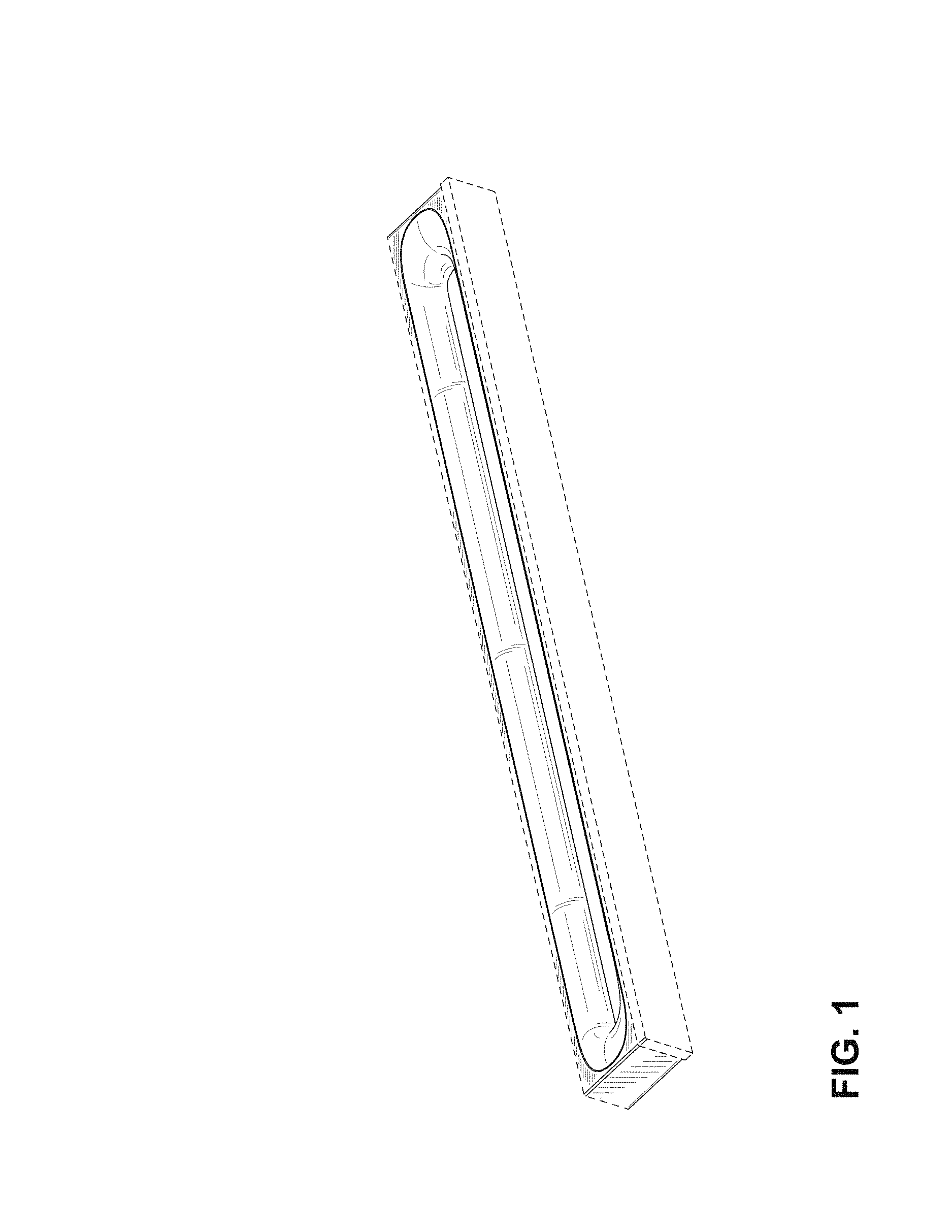
FIG. 1 is a front perspective view of one embodiment of a handle of the present disclosure;
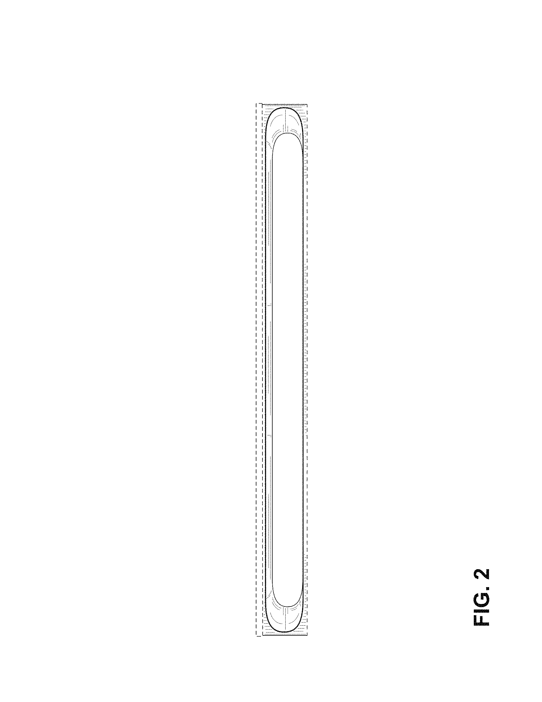
FIG. 2 is a top plan view of the handle of FIG. 1;
FIG. 3 is a bottom plan view of the handle of FIG. 1;
FIG. 4 is a first side elevational view of the handle of FIG. 1;
FIG. 5 is a second side elevational view of the handle of FIG. 1;
FIG. 6 is a front elevational view of the handle of FIG. 1;
FIG. 7 is a rear elevational view of the handle of FIG. 1;
FIG. 8 is a front perspective view of a second embodiment of a handle of the present disclosure;
FIG. 9 is a top plan view of the handle of FIG. 8;
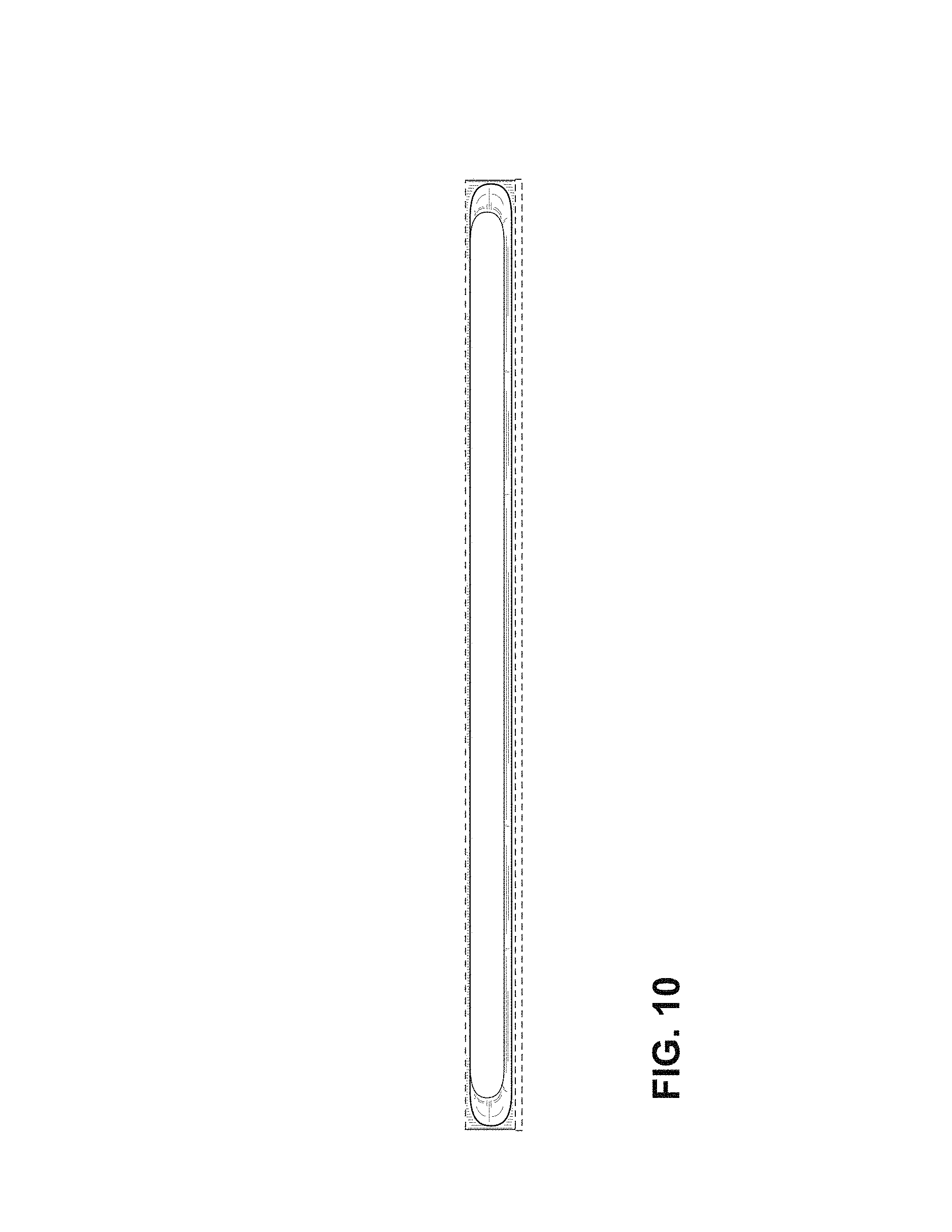
FIG. 10 is a bottom plan view of the handle of FIG. 8;
FIG. 11 is a first side elevational view of the handle of FIG. 8;
FIG. 12 is a second side elevational view of the handle of FIG. 8;
FIG. 13 is a front elevational view of the handle of FIG. 8;
FIG. 14 is a rear elevational view of the handle of FIG. 8;
FIG. 15 is a front perspective view of a third embodiment of a handle of the present disclosure;
FIG. 16 is a top plan view of the handle of FIG. 15;
FIG. 17 is a bottom plan view of the handle of FIG. 15;
FIG. 18 is a first side elevational view of the handle of FIG. 15;
FIG. 19 is a second side elevational view of the handle of FIG. 15;
FIG. 20 is a front elevational view of the handle of FIG. 15; and,
FIG. 21 is a rear elevational view of the handle of FIG. 15.
The broken lines depict portions of the article that form no part of the claimed design. FIGS. 15-17, 20, and 21 are shown with a symbolic break in its length. The appearance of any portion of the article between the break lines forms no part of the claimed design.
* * * * *
D00000
D00001
D00002
D00003
D00004
D00005
D00006
D00007
D00008
D00009
D00010
D00011
D00012

XML
uspto.report is an independent third-party trademark research tool that is not affiliated, endorsed, or sponsored by the United States Patent and Trademark Office (USPTO) or any other governmental organization. The information provided by uspto.report is based on publicly available data at the time of writing and is intended for informational purposes only.
While we strive to provide accurate and up-to-date information, we do not guarantee the accuracy, completeness, reliability, or suitability of the information displayed on this site. The use of this site is at your own risk. Any reliance you place on such information is therefore strictly at your own risk.
All official trademark data, including owner information, should be verified by visiting the official USPTO website at www.uspto.gov. This site is not intended to replace professional legal advice and should not be used as a substitute for consulting with a legal professional who is knowledgeable about trademark law.