Semiautomatic handgun
Shinkle , et al.
U.S. patent number D854,642 [Application Number D/632,270] was granted by the patent office on 2019-07-23 for semiautomatic handgun. This patent grant is currently assigned to Sig Sauer, Inc.. The grantee listed for this patent is Sig Sauer, Inc.. Invention is credited to Jason Knight, Tyler Michael Rainaud, Scott D. Shinkle, Matthew A. Taylor, Adrian Thomele.


View All Diagrams
| United States Patent | D854,642 |
| Shinkle , et al. | July 23, 2019 |
Semiautomatic handgun
Claims
CLAIM The ornamental design for a semiautomatic handgun, as shown and described.
| Inventors: | Shinkle; Scott D. (Greenland, NH), Thomele; Adrian (Stratham, NH), Taylor; Matthew A. (Barrington, NH), Rainaud; Tyler Michael (Rochester, NH), Knight; Jason (Exeter, NH) | ||||||||||
|---|---|---|---|---|---|---|---|---|---|---|---|
| Applicant: |
|
||||||||||
| Assignee: | Sig Sauer, Inc. (Newington,
NH) |
||||||||||
| Appl. No.: | D/632,270 | ||||||||||
| Filed: | January 5, 2018 |
| Current U.S. Class: | D22/104; D21/574 |
| Current International Class: | 2201 |
| Field of Search: | ;D21/301,304,567,570,571,573,574,575,746 ;D22/100,101,102,103,106,107,108,109,110,111,112,115,116,199 |
References Cited [Referenced By]
U.S. Patent Documents
| 1245499 | November 1917 | Gardner |
| 4099595 | July 1978 | Tracy |
| 4593601 | June 1986 | Smith |
| 5099595 | March 1992 | Chesnut et al. |
| D359098 | June 1995 | Stevens |
| D430916 | September 2000 | Bubits |
| 6401379 | June 2002 | Moon |
| 6568115 | May 2003 | Beretta |
| D479570 | September 2003 | Scheunert |
| D593629 | June 2009 | Bantle |
| D597625 | August 2009 | Pflaumer |
| D598065 | August 2009 | Vukovic |
| D627028 | November 2010 | Coulombier |
| D654978 | February 2012 | Karanian |
| D681131 | April 2013 | Su |
| 8448364 | May 2013 | Davidson |
| D688764 | August 2013 | Yigit |
| D690374 | September 2013 | Lee |
| D692513 | October 2013 | Yigit |
| 9021730 | May 2015 | Gentilini |
| D744049 | November 2015 | Chu |
| 9194654 | November 2015 | Viani |
| D754802 | April 2016 | Martelli |
| 9303936 | April 2016 | Toner |
| 9322610 | April 2016 | Zajk |
| D755324 | May 2016 | Martelli |
| D755907 | May 2016 | Hu |
| D758519 | June 2016 | Toner |
| 9441897 | September 2016 | Mather et al. |
| 9546831 | January 2017 | Bandini |
| 9551550 | January 2017 | Wells |
| 9664471 | May 2017 | Curry |
| D791262 | July 2017 | Brown |
| D803341 | November 2017 | Wolf |
| D808487 | January 2018 | Beville |
| D814593 | April 2018 | O'Clair |
| D814596 | April 2018 | Curry |
| D815233 | April 2018 | Toner |
| D823969 | July 2018 | Beville |
| 10024629 | July 2018 | Sheets, Jr. |
| D828881 | September 2018 | Lee |
| D828892 | September 2018 | Kellgren |
| D830480 | October 2018 | Chu |
| 10088269 | October 2018 | Sheets, Jr. |
| D834656 | November 2018 | Chu |
| 10119777 | November 2018 | Wolf |
| 2001/0037596 | November 2001 | Salvitti |
| 2008/0034955 | February 2008 | McGarry |
| 2009/0071053 | March 2009 | Thomele |
| 2017/0146309 | May 2017 | Biran |
| 2017/0184359 | June 2017 | Porat |
Other References
|
"SIG P365 High-Capacity Micro-Compact Pistol" [online]. SIG Sauer, Inc. [Published on Jan. 8, 2018]. Retrieved from the Internet: <https://www.youtube.com/watch?v=0fvwq6-nWiE>. cited by examiner . Ruger American Pistol Pro Model Parts List, pp. 34-37 (2016). cited by applicant . "Instruction Manual for Ruger American Pistol Pro Model", Sturm, Ruger & Co., Inc., (2016). cited by applicant . "Instruction Manual for Ruger American Pistol, Standard Model", Sturm, Ruger & Co., Inc., (2016). cited by applicant. |
Primary Examiner: Anwar; Khawaja
Assistant Examiner: Tehrani; Mojtaba
Attorney, Agent or Firm: Finch & Maloney PLLC
Description
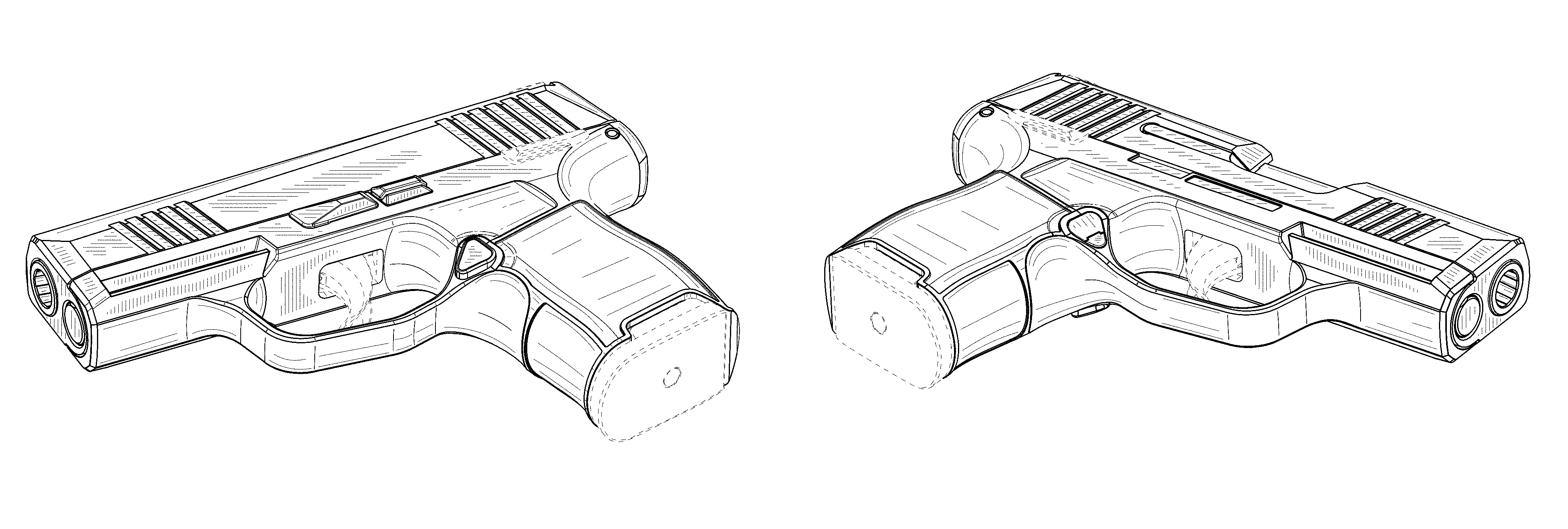
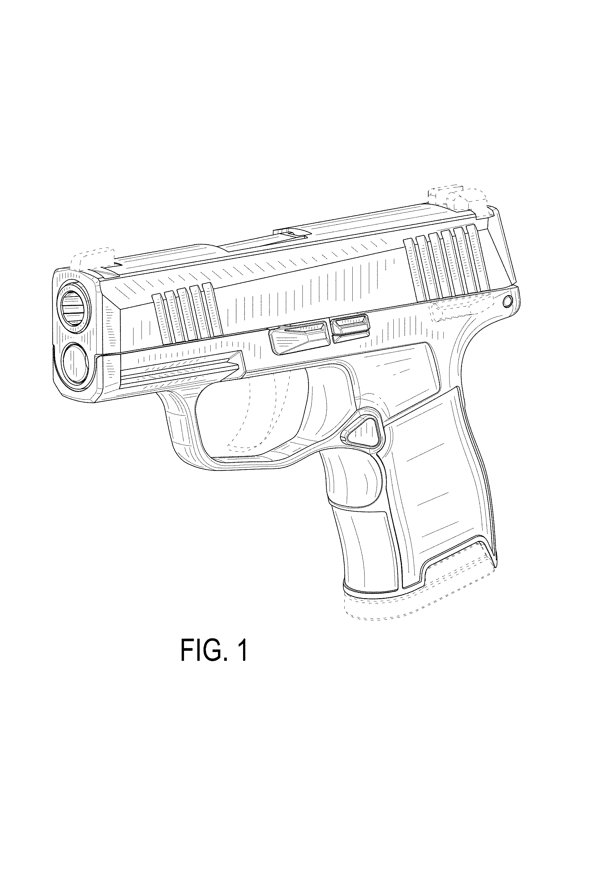
FIG. 1 is a front, top left-side perspective view of a semiautomatic handgun showing our new design;
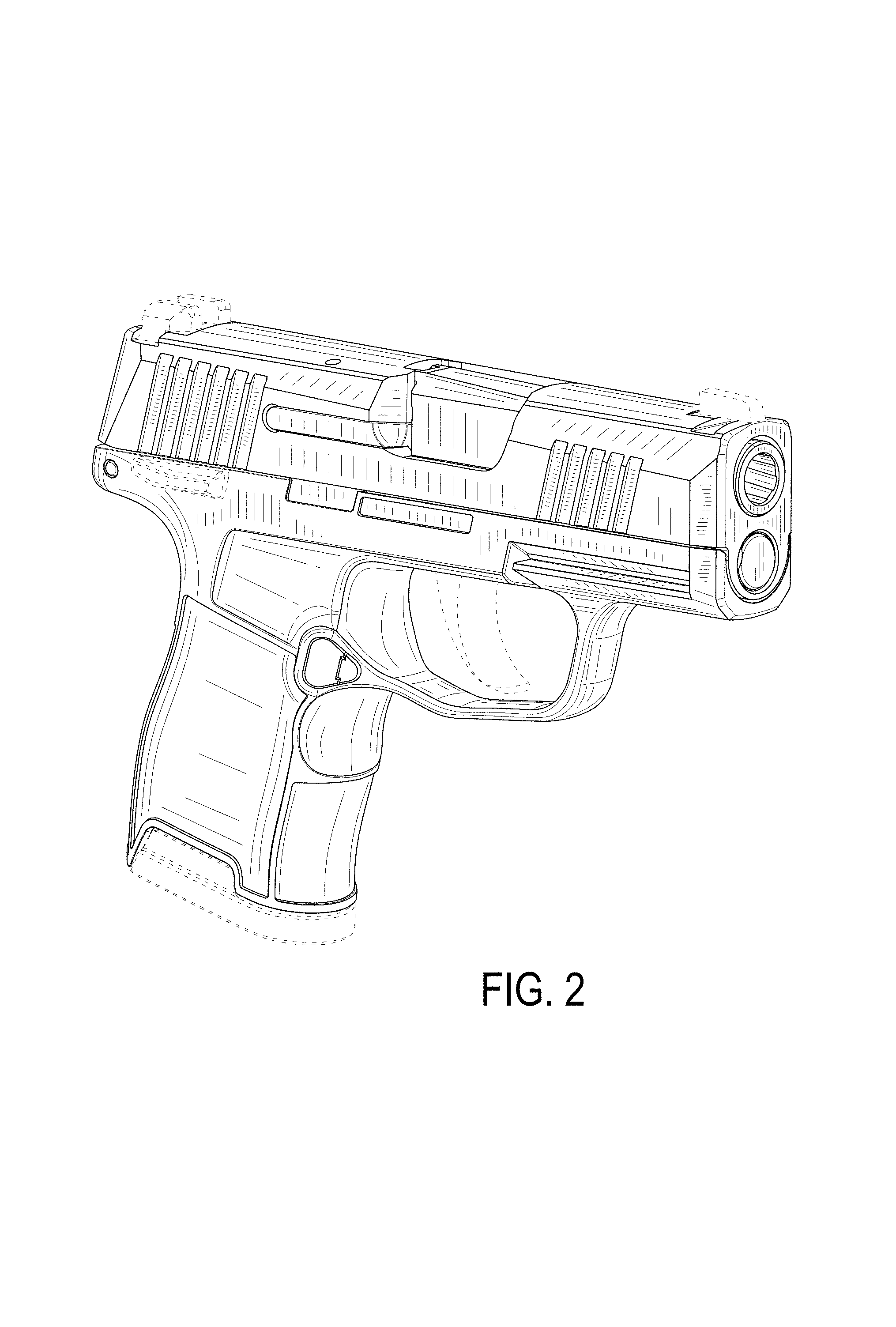
FIG. 2 is a right-side, front, and top perspective view thereof;
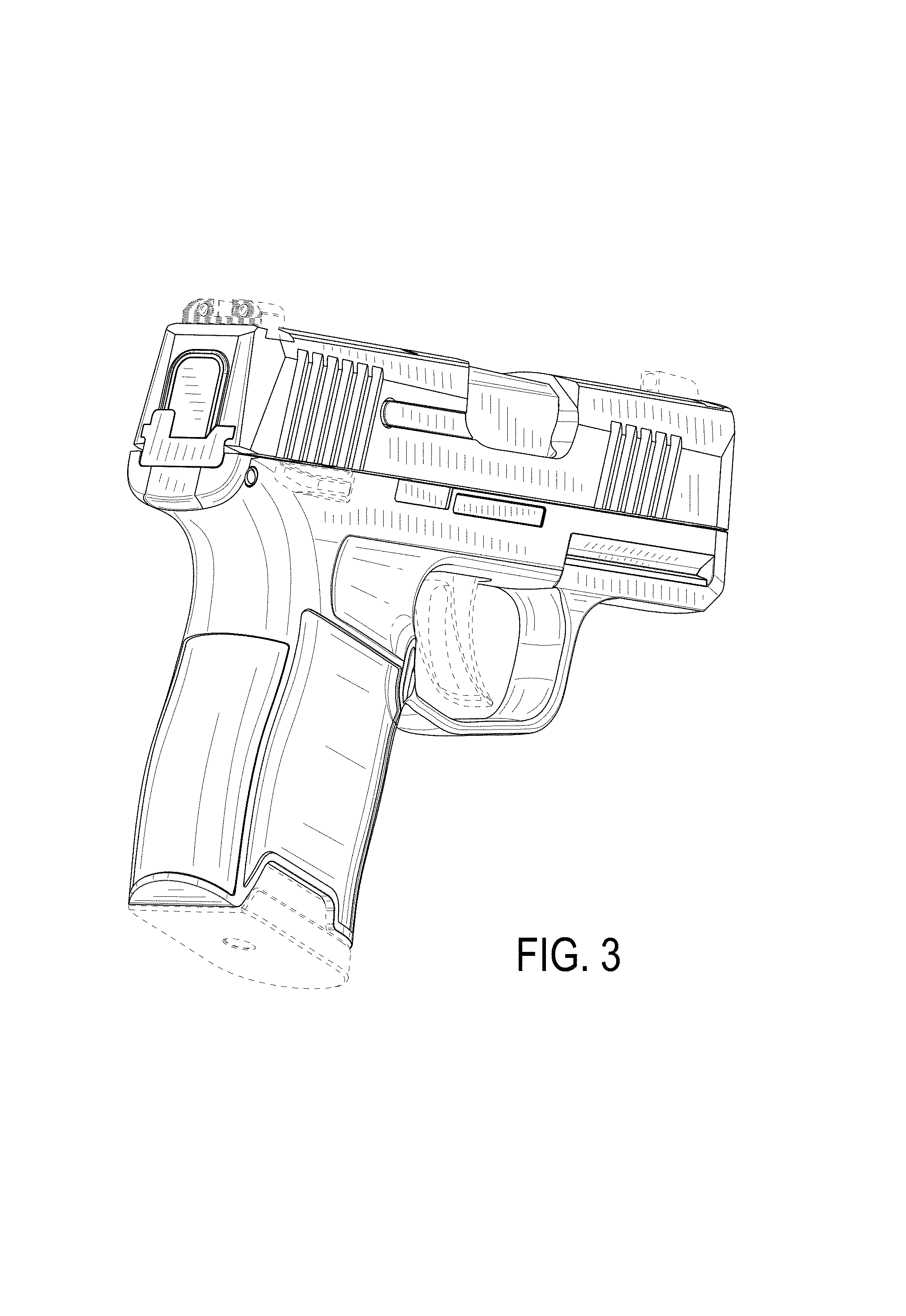
FIG. 3 is a right-side, rear, and bottom perspective view thereof;
FIG. 4 is a left-side, rear, and bottom perspective view thereof;
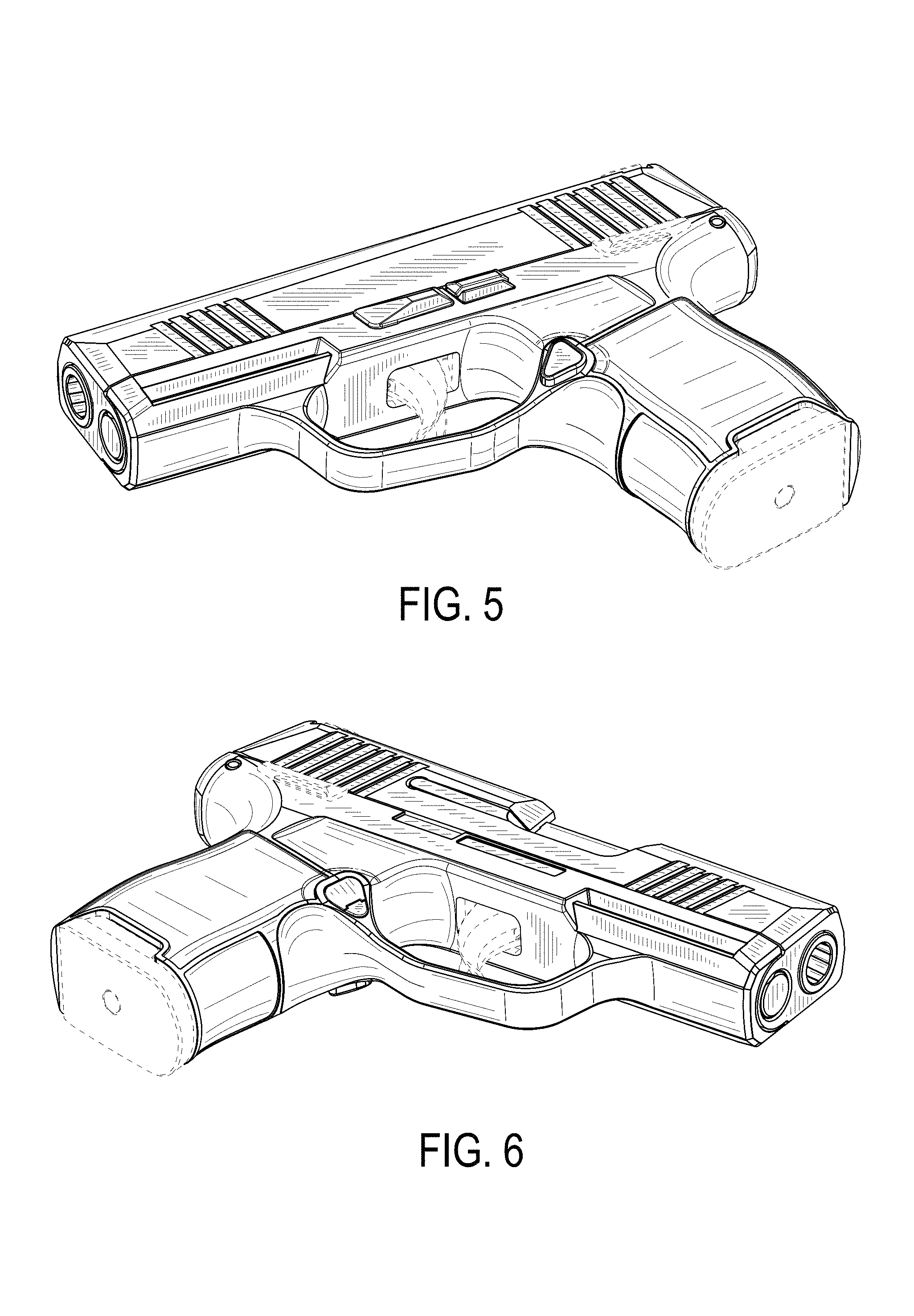
FIG. 5 is a bottom, left-side, and front perspective view thereof;
FIG. 6 is a bottom, right-side, and front perspective view thereof;
FIG. 7 is a top, left-side, and rear perspective view thereof;
FIG. 8 is a top, right-side, and rear perspective view thereof;
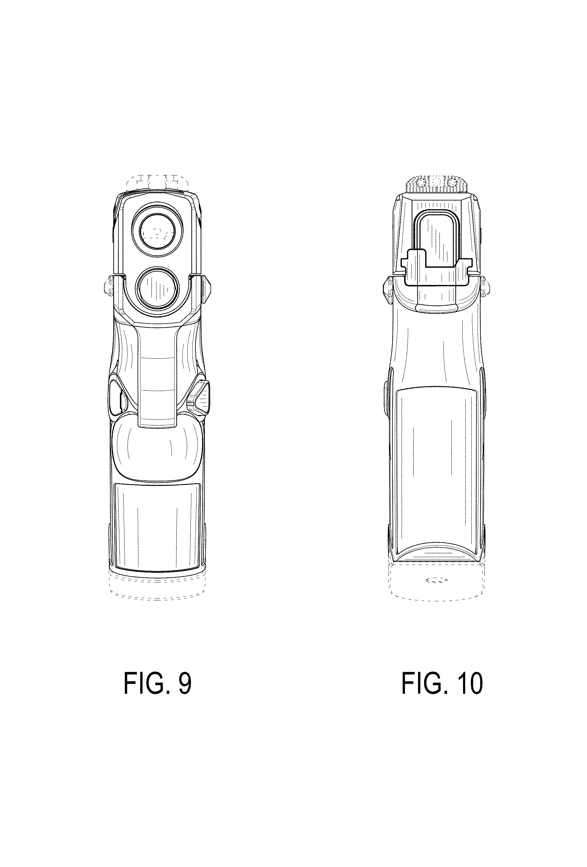
FIG. 9 is a front elevational view thereof;
FIG. 10 is a rear elevational view thereof;
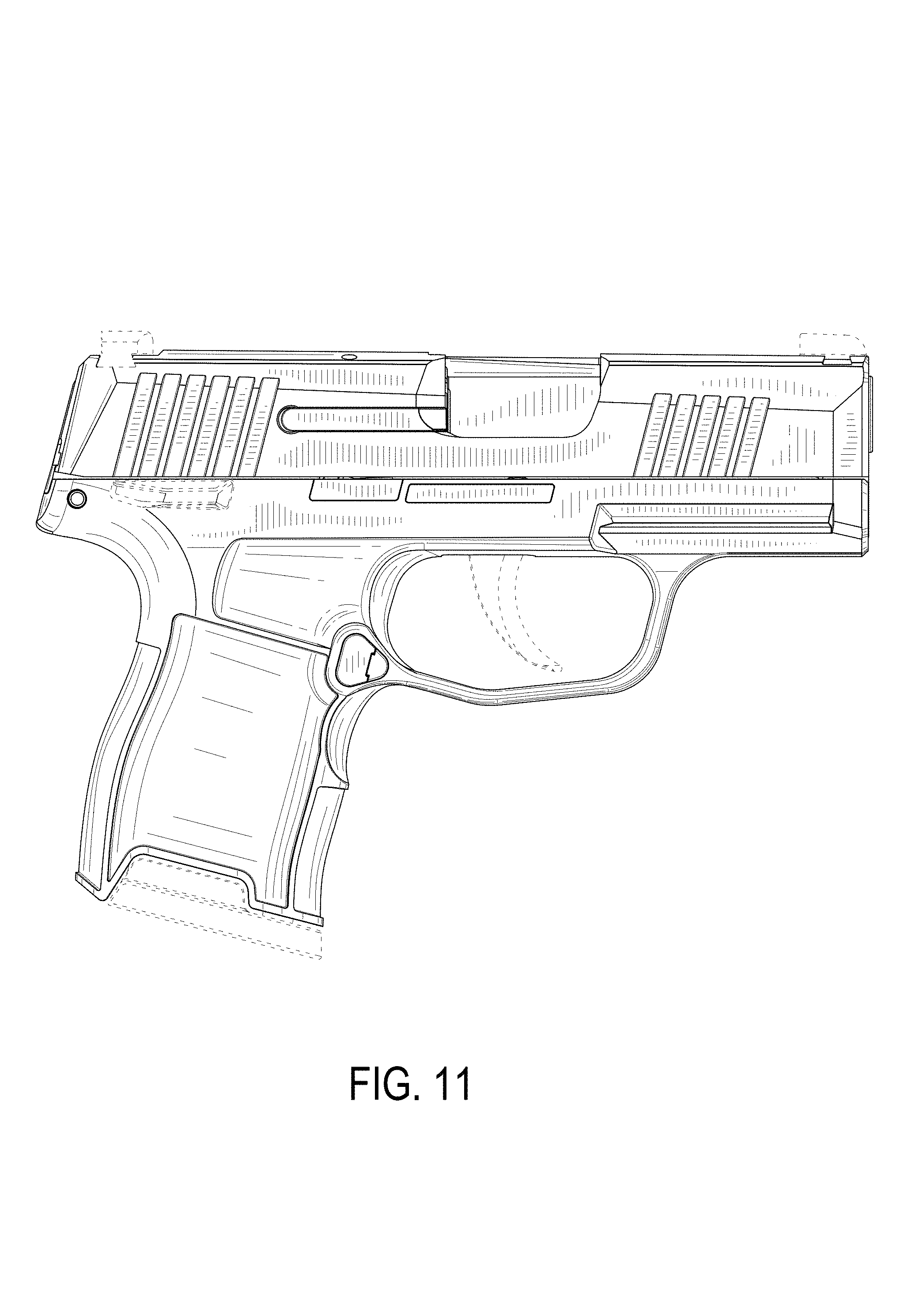
FIG. 11 is right-side elevational view thereof;
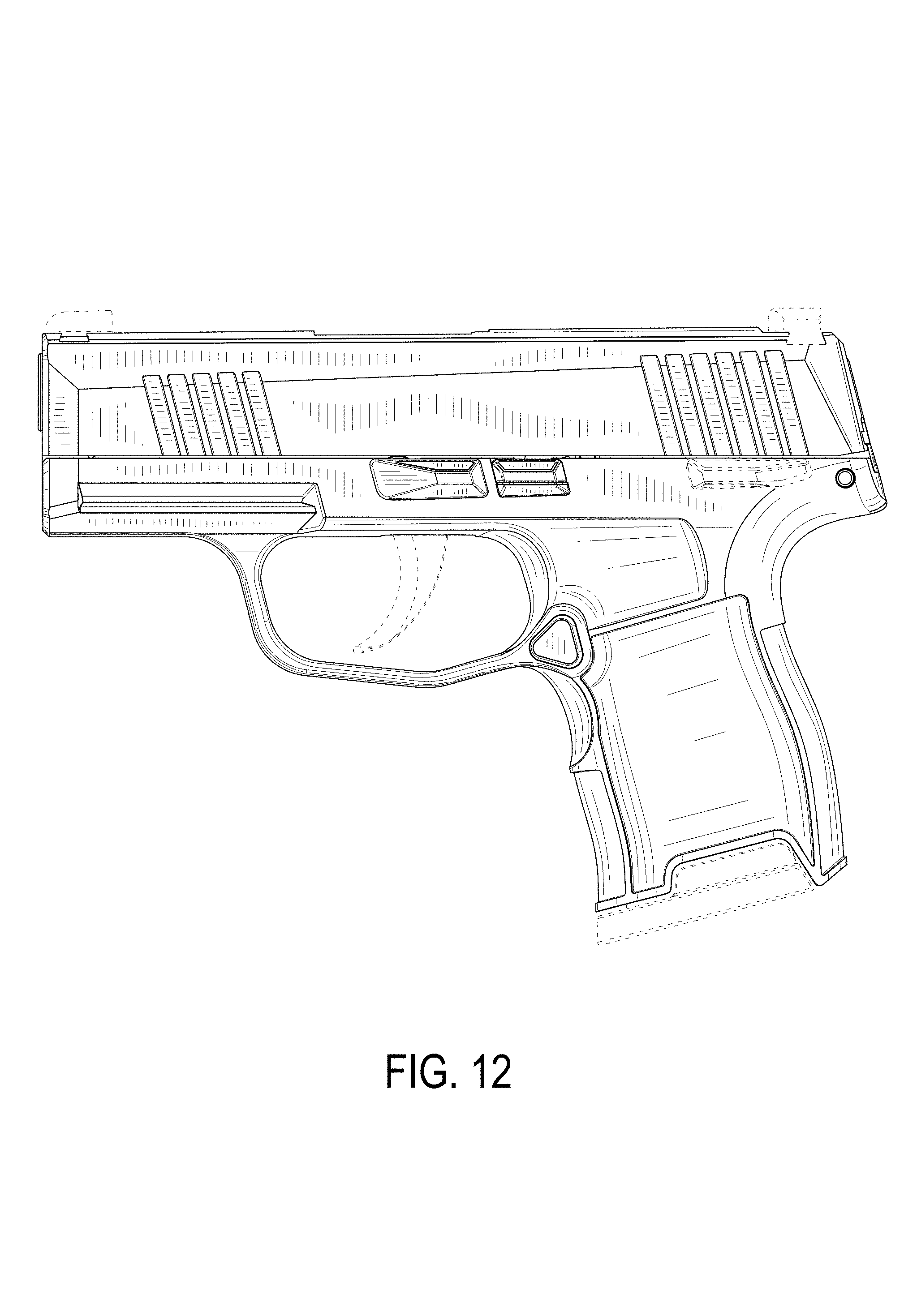
FIG. 12 is left-side elevational view thereof;
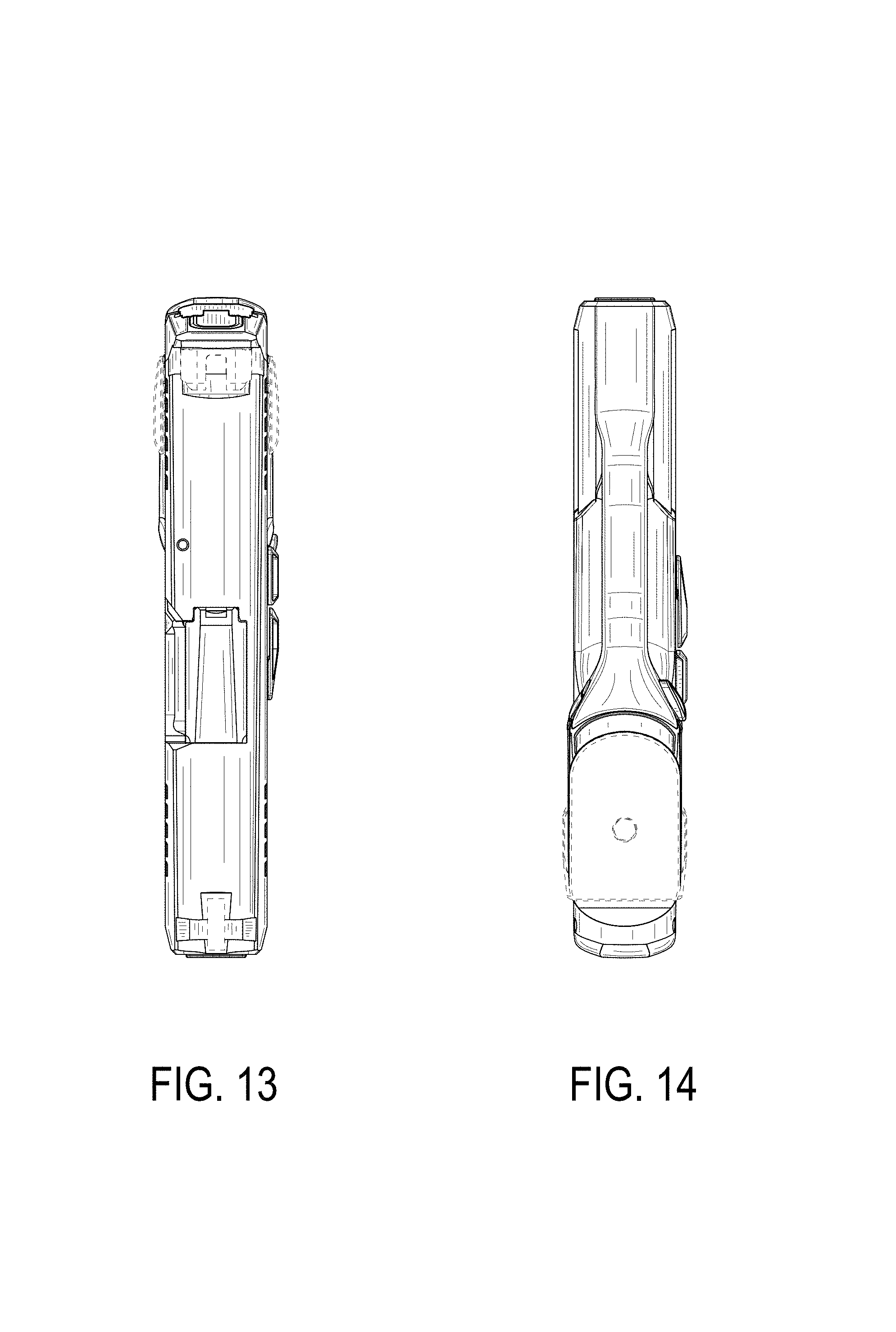
FIG. 13 is a top plan view thereof;
FIG. 14 is a bottom plan view thereof;
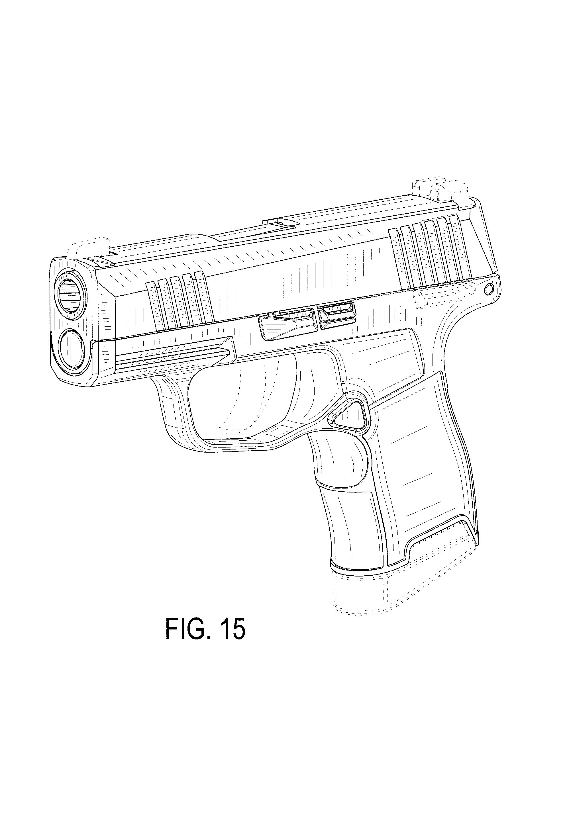
FIG. 15 is a front, top left-side perspective view thereof;
FIG. 16 is a front, top left-side perspective view thereof; and,
FIG. 17 is a front, top left-side perspective view thereof.
Broken lines in the drawings are for the purpose of illustrating environmental structure and form no part of the claimed design.
* * * * *
References
D00000
D00001
D00002
D00003
D00004
D00005
D00006
D00007
D00008
D00009
D00010
D00011
D00012

D00013

XML
uspto.report is an independent third-party trademark research tool that is not affiliated, endorsed, or sponsored by the United States Patent and Trademark Office (USPTO) or any other governmental organization. The information provided by uspto.report is based on publicly available data at the time of writing and is intended for informational purposes only.
While we strive to provide accurate and up-to-date information, we do not guarantee the accuracy, completeness, reliability, or suitability of the information displayed on this site. The use of this site is at your own risk. Any reliance you place on such information is therefore strictly at your own risk.
All official trademark data, including owner information, should be verified by visiting the official USPTO website at www.uspto.gov. This site is not intended to replace professional legal advice and should not be used as a substitute for consulting with a legal professional who is knowledgeable about trademark law.