Weighted golf club grip
Rogacki
U.S. patent number D854,640 [Application Number D/611,902] was granted by the patent office on 2019-07-23 for weighted golf club grip. The grantee listed for this patent is Edward Rogacki. Invention is credited to Edward Rogacki.


| United States Patent | D854,640 |
| Rogacki | July 23, 2019 |
Weighted golf club grip
Claims
CLAIM The ornamental design for a weighted golf club grip, as shown and described.
| Inventors: | Rogacki; Edward (Cooper City, FL) | ||||||||||
|---|---|---|---|---|---|---|---|---|---|---|---|
| Applicant: |
|
||||||||||
| Appl. No.: | D/611,902 | ||||||||||
| Filed: | July 26, 2017 |
Related U.S. Patent Documents
| Application Number | Filing Date | Patent Number | Issue Date | ||
|---|---|---|---|---|---|
| 14929568 | Nov 2, 2015 | ||||
| 14253267 | Apr 15, 2014 | 9174104 | |||
| Current U.S. Class: | D21/756 |
| Current International Class: | 2102 |
| Field of Search: | ;D21/756-759,789 |
References Cited [Referenced By]
U.S. Patent Documents
| 1210182 | December 1916 | Lynch |
| 1658447 | February 1928 | Lantz |
| 1696462 | December 1928 | Victor |
| 3075768 | January 1963 | Karns |
| 4461479 | July 1984 | Mitchell |
| 4600195 | July 1986 | Hunter |
| 4936586 | June 1990 | Van Raemdonck |
| 4988102 | January 1991 | Reisner |
| D314600 | February 1991 | Tosti |
| D319278 | August 1991 | Tosti |
| 5244209 | September 1993 | Benzel |
| 6022281 | February 2000 | Nolan |
| 6354958 | March 2002 | Meyer |
| 6441745 | August 2002 | Gates |
| 6656057 | December 2003 | Manual et al. |
| 7399235 | July 2008 | Gill |
| 7481716 | January 2009 | Johnson |
| D633966 | March 2011 | Savarese |
| 7909705 | March 2011 | Gill et al. |
| D649609 | November 2011 | Savarese |
| D652097 | January 2012 | Gill |
| 8419565 | April 2013 | Karube |
| 8888606 | November 2014 | Boccieri |
| 9174104 | November 2015 | Rogacki |
| 9694265 | July 2017 | Margoles |
| 2004/0053715 | March 2004 | Schwieg et al. |
| 2011/0124431 | May 2011 | Karube |
| 2011/0159982 | June 2011 | Takeuchi |
Attorney, Agent or Firm: Bowen; Mark D. Malin Haley DiMaggio & Bowen, P.A.
Description
FIG. 1 is a top perspective view of a weighted golf club grip in accordance with the present invention;
FIG. 2 is a bottom perspective view thereof;
FIG. 3 is a side view thereof;
FIG. 4 is top view thereof;
FIG. 5 is bottom view thereof;
FIG. 6 is an exploded front side view thereof;
FIG. 7 is an exploded rear side view thereof;
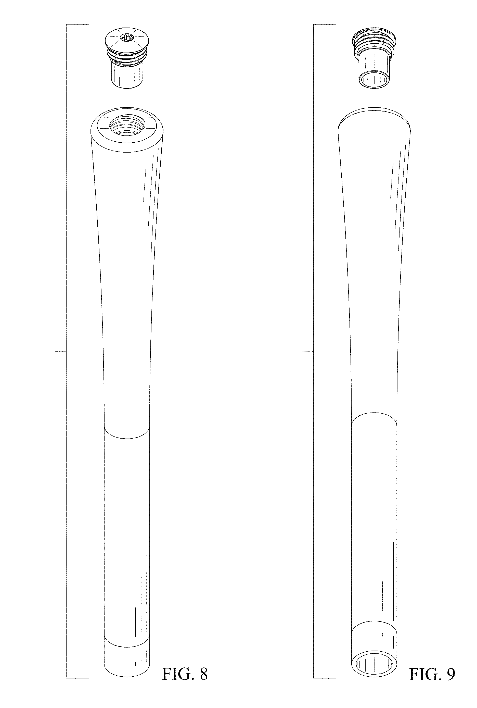
FIG. 8 is an exploded top perspective view thereof; and,
FIG. 9 is an exploded bottom perspective view thereof.
* * * * *
D00000
D00001
D00002
D00003
D00004
XML
uspto.report is an independent third-party trademark research tool that is not affiliated, endorsed, or sponsored by the United States Patent and Trademark Office (USPTO) or any other governmental organization. The information provided by uspto.report is based on publicly available data at the time of writing and is intended for informational purposes only.
While we strive to provide accurate and up-to-date information, we do not guarantee the accuracy, completeness, reliability, or suitability of the information displayed on this site. The use of this site is at your own risk. Any reliance you place on such information is therefore strictly at your own risk.
All official trademark data, including owner information, should be verified by visiting the official USPTO website at www.uspto.gov. This site is not intended to replace professional legal advice and should not be used as a substitute for consulting with a legal professional who is knowledgeable about trademark law.