Remote control
Zhang , et al.
U.S. patent number D854,518 [Application Number D/612,632] was granted by the patent office on 2019-07-23 for remote control. This patent grant is currently assigned to Comcast Cable Communications, LLC. The grantee listed for this patent is Comcast Cable Communications, LLC. Invention is credited to Neil Epstein, Henry Homza, Michael Jou, Thomas Loretan, Fraser Stirling, Zhe Zhang.


| United States Patent | D854,518 |
| Zhang , et al. | July 23, 2019 |
Remote control
Claims
CLAIM The ornamental design for a remote control, as shown and described.
| Inventors: | Zhang; Zhe (New York, NY), Epstein; Neil (Philadelphia, PA), Homza; Henry (Philadelphia, PA), Jou; Michael (Philadelphia, PA), Stirling; Fraser (Mawr, PA), Loretan; Thomas (Philadelphia, PA) | ||||||||||
|---|---|---|---|---|---|---|---|---|---|---|---|
| Applicant: |
|
||||||||||
| Assignee: | Comcast Cable Communications,
LLC (Philadelphia, PA) |
||||||||||
| Appl. No.: | D/612,632 | ||||||||||
| Filed: | August 2, 2017 |
| Current U.S. Class: | D14/218; D13/168 |
| Current International Class: | 1403 |
| Field of Search: | ;D13/162,168 ;D10/49,104.1,106.1 ;D14/140,216,217,218,358 |
References Cited [Referenced By]
U.S. Patent Documents
| D406542 | March 1999 | Mik |
| D496005 | September 2004 | Wang |
| D598009 | August 2009 | Painter |
| D614145 | April 2010 | Arosio |
| D673512 | January 2013 | Huang |
| D700904 | March 2014 | Miller |
| D701841 | April 2014 | Huang |
| D702194 | April 2014 | Cho |
| D729773 | May 2015 | Salojarvi |
| D737250 | August 2015 | Ingham |
| D746794 | January 2016 | Conrad |
| D775117 | December 2016 | Choi |
| D778264 | February 2017 | Stapelbroek |
| D778878 | February 2017 | de Vaal |
| D782430 | March 2017 | Tam |
| D796975 | September 2017 | Jou |
| D800081 | October 2017 | Koo |
| D801273 | October 2017 | Jou |
| D808389 | January 2018 | Judge |
| D813230 | March 2018 | Koo |
| D816046 | April 2018 | Kiong |
| 2003/0122698 | July 2003 | Horie |
Attorney, Agent or Firm: Baker & Hostetler LLP
Description
FIG. 1 is a top perspective view of a remote control according to an aspect of the present disclosure;
FIG. 2 is a bottom perspective view of the remote control of FIG. 1;
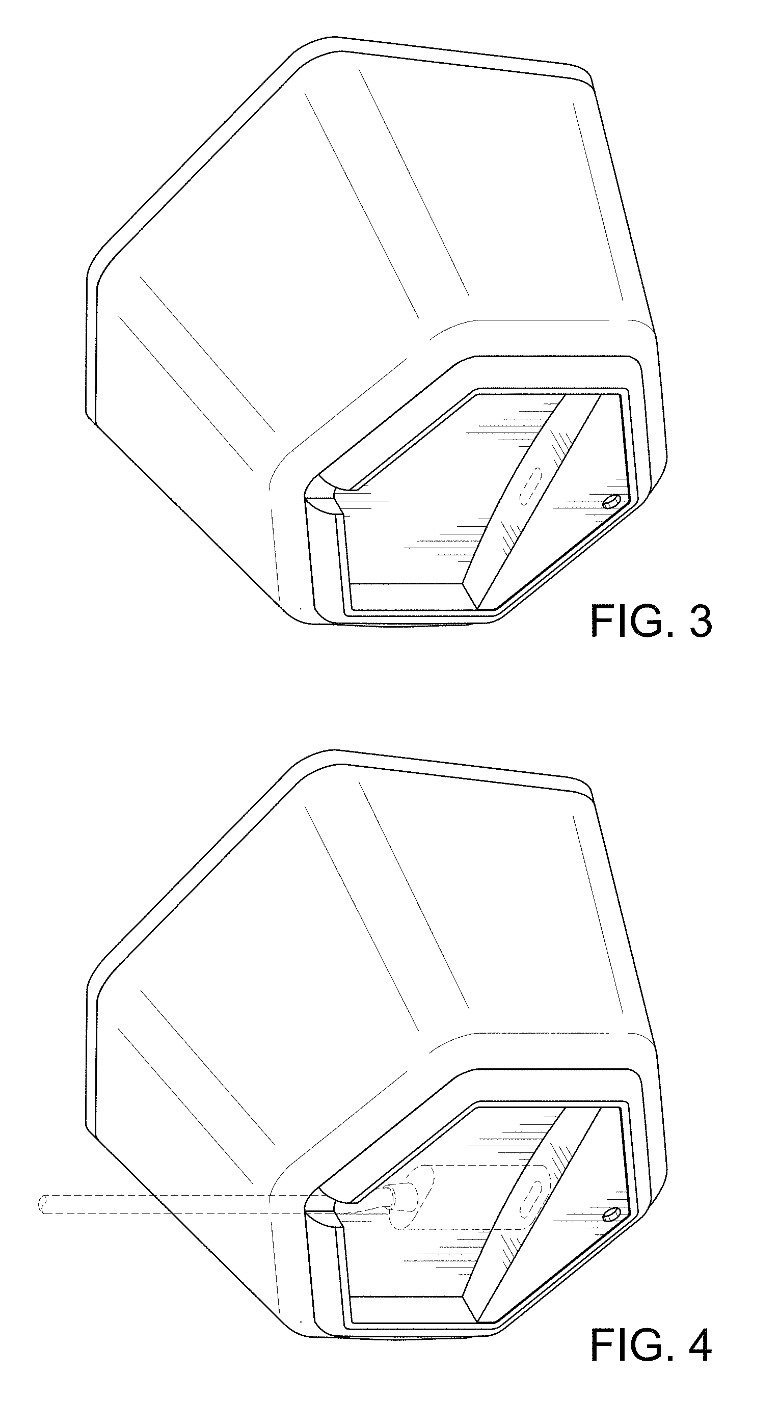
FIG. 3 is a bottom perspective view of the remote control of FIG. 2, rotated clockwise relative to the view shown in FIG. 2;
FIG. 4 is a bottom perspective view of the remote control of FIG. 2, rotated clockwise relative to the view shown in FIG. 2 and showing a broken line of a power cord;
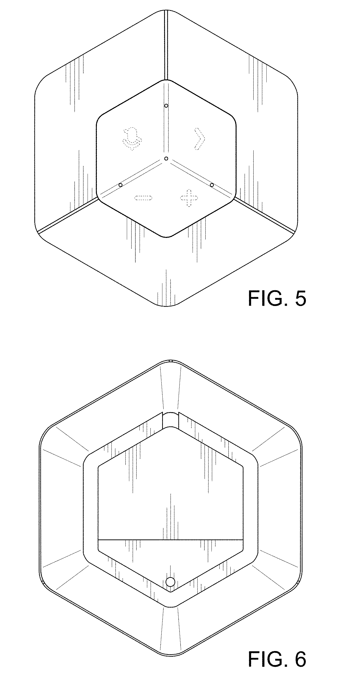
FIG. 5 is a top plan view of the remote control of FIG. 1;
FIG. 6 is a bottom plan view of the remote control of FIG. 1;
FIG. 7 is a front view of the remote control of FIG. 1;
FIG. 8 is a back view of the remote control of FIG. 1;
FIG. 9 is a left side view of the remote control of FIG. 1;
FIG. 10 is a right side view of the remote control of FIG. 1;
FIG. 11 is a top perspective view of a remote control according to another aspect of the present disclosure; and,
FIG. 12 is a top plan view of the remote control of FIG. 11.
The broken line portion of the remote control is included to show unclaimed subject matter only for the purpose of illustrating environment and forms no part of the claimed design.
* * * * *
D00000
D00001
D00002
D00003
D00004
D00005
D00006
XML
uspto.report is an independent third-party trademark research tool that is not affiliated, endorsed, or sponsored by the United States Patent and Trademark Office (USPTO) or any other governmental organization. The information provided by uspto.report is based on publicly available data at the time of writing and is intended for informational purposes only.
While we strive to provide accurate and up-to-date information, we do not guarantee the accuracy, completeness, reliability, or suitability of the information displayed on this site. The use of this site is at your own risk. Any reliance you place on such information is therefore strictly at your own risk.
All official trademark data, including owner information, should be verified by visiting the official USPTO website at www.uspto.gov. This site is not intended to replace professional legal advice and should not be used as a substitute for consulting with a legal professional who is knowledgeable about trademark law.