Electrical power connector
Gieski , et al.
U.S. patent number D854,503 [Application Number D/637,096] was granted by the patent office on 2019-07-23 for electrical power connector. This patent grant is currently assigned to FCI USA LLC. The grantee listed for this patent is FCI USA LLC. Invention is credited to Michael Blanchfield, Christopher S. Gieski, Michael Percherke.


| United States Patent | D854,503 |
| Gieski , et al. | July 23, 2019 |
Electrical power connector
Claims
CLAIM The ornamental design for an electrical power connector, as shown and described.
| Inventors: | Gieski; Christopher S. (Gardners, PA), Blanchfield; Michael (Mechanicsburg, PA), Percherke; Michael (Enola, PA) | ||||||||||
|---|---|---|---|---|---|---|---|---|---|---|---|
| Applicant: |
|
||||||||||
| Assignee: | FCI USA LLC (Etters,
PA) |
||||||||||
| Appl. No.: | D/637,096 | ||||||||||
| Filed: | February 13, 2018 |
Related U.S. Patent Documents
| Application Number | Filing Date | Patent Number | Issue Date | ||
|---|---|---|---|---|---|
| 29544772 | Nov 6, 2015 | D813167 | |||
| Current U.S. Class: | D13/147 |
| Current International Class: | 1303 |
| Field of Search: | ;D13/133,146,147,154,184,199 |
References Cited [Referenced By]
U.S. Patent Documents
| 3033914 | May 1962 | Alfonso |
| 5267876 | December 1993 | Rupert et al. |
| 6402566 | June 2002 | Middlehurst et al. |
| D520454 | May 2006 | Riku |
| 7258562 | August 2007 | Daily et al. |
| D556140 | November 2007 | Sakamoto |
| D616827 | June 2010 | Ngo et al. |
| D629761 | December 2010 | Ngo et al. |
| D686159 | July 2013 | Takahashi et al. |
| D765035 | August 2016 | Buck |
| 9419356 | August 2016 | Copper |
| D780125 | February 2017 | Yang |
| D785571 | May 2017 | Buck |
| D813167 | March 2018 | Gieski |
| D813168 | March 2018 | Gieski |
| 2006/0189194 | August 2006 | Daily et al. |
Other References
|
US. Appl. No. 29/544,772, filed Nov. 6, 2015, Gieski et al. cited by applicant . Molex, Extreme OrthoPower Orthogonal Direct-Power Connector System; www.molex.com/link/extremeorthopower.html; 2014. cited by applicant. |
Primary Examiner: Bui; Daniel D
Attorney, Agent or Firm: Wolf, Greenfield & Sacks, P.C.
Description
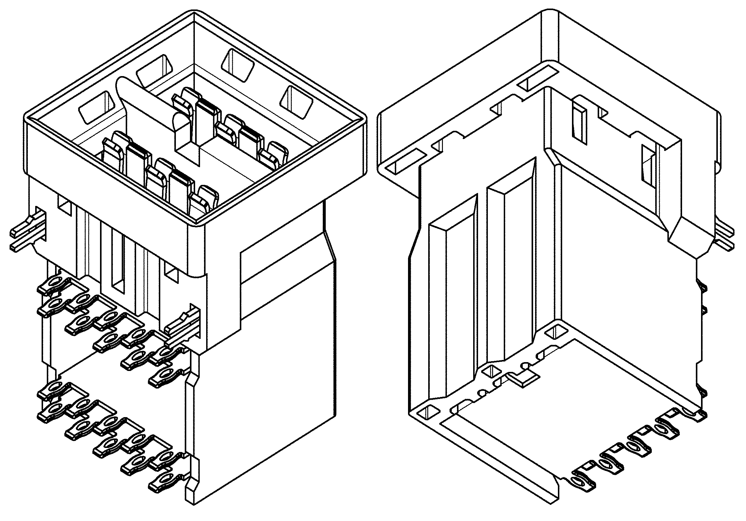
FIG. 1 is a bottom, left, front perspective view of an electrical power connector according to our new design;
FIG. 2 is a top, right, rear perspective view of thereof;
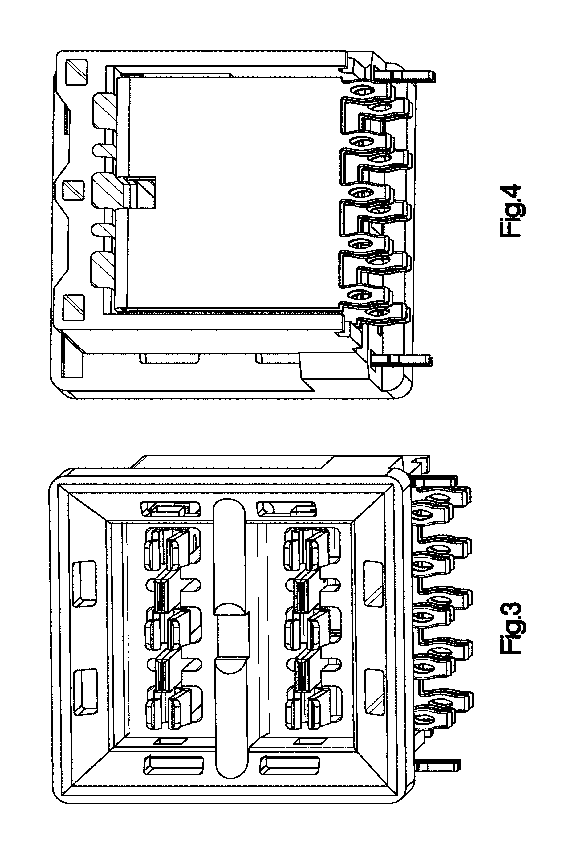
FIG. 3 is another bottom, left, front perspective view thereof;
FIG. 4 is a bottom, left, rear perspective view thereof;
FIG. 5 is a top, right, rear perspective view thereof;
FIG. 6 is another bottom, left, rear perspective view thereof;
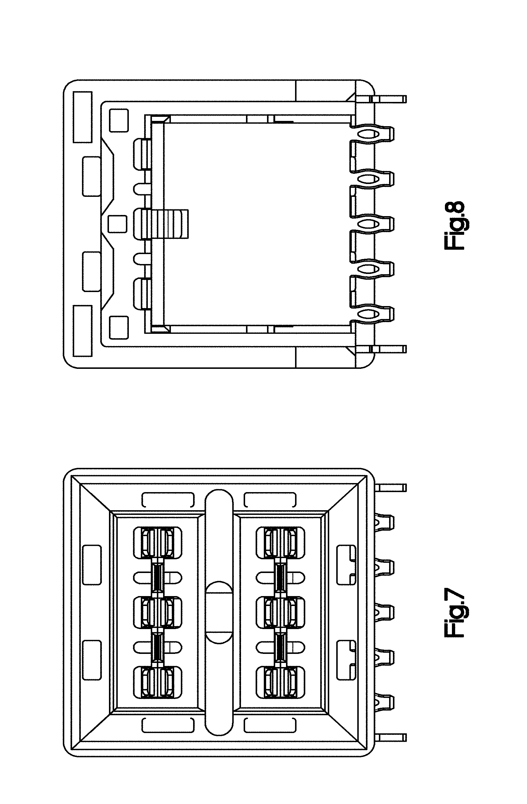
FIG. 7 is a front elevation view thereof;
FIG. 8 is a rear elevation view thereof;
FIG. 9 is a right side elevation view thereof;
FIG. 10 is a left side elevation view thereof;
FIG. 11 is a top plan view thereof; and,
FIG. 12 is a bottom plan view thereof.
* * * * *
References
D00000
D00001
D00002
D00003
D00004
D00005
D00006
XML
uspto.report is an independent third-party trademark research tool that is not affiliated, endorsed, or sponsored by the United States Patent and Trademark Office (USPTO) or any other governmental organization. The information provided by uspto.report is based on publicly available data at the time of writing and is intended for informational purposes only.
While we strive to provide accurate and up-to-date information, we do not guarantee the accuracy, completeness, reliability, or suitability of the information displayed on this site. The use of this site is at your own risk. Any reliance you place on such information is therefore strictly at your own risk.
All official trademark data, including owner information, should be verified by visiting the official USPTO website at www.uspto.gov. This site is not intended to replace professional legal advice and should not be used as a substitute for consulting with a legal professional who is knowledgeable about trademark law.