Vibratory screening machine
Colgrove , et al. July 16, 2
U.S. patent number D854,066 [Application Number D/644,138] was granted by the patent office on 2019-07-16 for vibratory screening machine. This patent grant is currently assigned to Derrick Corporation. The grantee listed for this patent is Derrick Corporation. Invention is credited to James R. Colgrove, Michael L. Peresan.


| United States Patent | D854,066 |
| Colgrove , et al. | July 16, 2019 |
Vibratory screening machine
Claims
CLAIM The ornamental design for a vibratory screening machine, as shown and described.
| Inventors: | Colgrove; James R. (Holland, NY), Peresan; Michael L. (Strykersville, NY) | ||||||||||
|---|---|---|---|---|---|---|---|---|---|---|---|
| Applicant: |
|
||||||||||
| Assignee: | Derrick Corporation (Buffalo,
NY) |
||||||||||
| Family ID: | 61902937 | ||||||||||
| Appl. No.: | D/644,138 | ||||||||||
| Filed: | April 15, 2018 |
Related U.S. Patent Documents
| Application Number | Filing Date | Patent Number | Issue Date | ||
|---|---|---|---|---|---|
| 15785141 | Oct 16, 2017 | ||||
| Current U.S. Class: | D15/147 |
| Current CPC Class: | B07B1/48 20130101; B07B1/36 20130101; B07B1/46 20130101; B07B13/16 20130101; B07B1/28 20130101; B07B2201/04 20130101; B07B2230/01 20130101 |
| Current International Class: | 1509 |
| Field of Search: | ;D15/122,147 |
References Cited [Referenced By]
U.S. Patent Documents
| 790572 | May 1905 | Hickman |
| 821874 | May 1906 | Kirksey |
| 2576794 | November 1951 | Jost et al. |
| 2784842 | March 1957 | Cover |
| D203480 | January 1966 | Gardner |
| 3232431 | February 1966 | Musschoot et al. |
| 3241671 | March 1966 | Brauchla |
| 3439800 | April 1969 | Tonjes |
| 3642133 | February 1972 | Venanzetti |
| 3680697 | August 1972 | Hubach |
| 3688902 | September 1972 | Hubach |
| 4065382 | December 1977 | Derrick, Jr. |
| 4234416 | November 1980 | Lower et al. |
| 4572782 | February 1986 | Smith et al. |
| 4575421 | March 1986 | Derrick et al. |
| 4576713 | March 1986 | Melin |
| 4632751 | December 1986 | Johnson et al. |
| 4840728 | June 1989 | Connolly |
| 4861463 | August 1989 | Slesarenko |
| 4882054 | November 1989 | Derrick |
| 5100539 | March 1992 | Tsutsumi |
| 5199574 | April 1993 | Hollyfield, Jr. et al. |
| 5273164 | December 1993 | Lyon |
| 5322170 | June 1994 | Hadden |
| 5332101 | July 1994 | Bakula |
| 5337901 | August 1994 | Skaer |
| 5417858 | May 1995 | Derrick et al. |
| 5417859 | May 1995 | Bakula |
| D360888 | August 1995 | Timm |
| 5538139 | June 1996 | Keller |
| 5614094 | March 1997 | Deister |
| 5749471 | May 1998 | Andersson |
| 6142308 | November 2000 | Ghosh et al. |
| 6431366 | August 2002 | Fallon |
| 6540089 | April 2003 | Brock |
| 6698594 | March 2004 | Cohen |
| 6736271 | May 2004 | Hall |
| 7273150 | September 2007 | Fridman |
| D589992 | April 2009 | Murphy |
| D630659 | January 2011 | Dibbs |
| 8002116 | August 2011 | Cato |
| D732095 | June 2015 | Enfantino |
| 9409209 | September 2016 | Wojciechowski |
| D768745 | October 2016 | Vetter |
| D776733 | January 2017 | Convery |
| D822084 | July 2018 | Hodgkiss |
| D826301 | August 2018 | Vallelly |
| 2001/0052484 | December 2001 | Fallon |
| 2002/0153287 | October 2002 | Fallon |
| 2003/0178346 | September 2003 | Colgrove |
| 2003/0230541 | December 2003 | Derrick |
| 2005/0045052 | March 2005 | Cohen |
| 2005/0082236 | April 2005 | Derrick |
| 2006/0011520 | January 2006 | Schulte |
| 2006/0254964 | November 2006 | Richardson |
| 2007/0227954 | October 2007 | Nogalski |
| 2008/0093268 | April 2008 | Hukki et al. |
| 2008/0230448 | September 2008 | Wojciechowski |
| 2009/0173671 | July 2009 | O'Keeffe |
| 2009/0294335 | December 2009 | Roppo et al. |
| 2010/0018909 | January 2010 | Smith |
| 2010/0308144 | December 2010 | Vroom |
| 2013/0220892 | August 2013 | Wojciechowski |
| 2013/0313168 | November 2013 | Wojciechowski |
| 2014/0262978 | September 2014 | Wojciechowski |
| 2014/0263103 | September 2014 | Peresan et al. |
| 2015/0224541 | August 2015 | Dickinson et al. |
| 2016/0158802 | June 2016 | Ong |
| 2016/0158805 | June 2016 | Massman |
| 2016/0207069 | July 2016 | Pomerleau |
| 2016/0310994 | October 2016 | Wojciechowski |
| 2018/0104719 | April 2018 | Colgrove |
| 2015002647 | Apr 2016 | CL | |||
| 2018000975 | Jul 2018 | CL | |||
| 201183045 | Jan 2009 | CN | |||
| 201337984 | Nov 2009 | CN | |||
| 106824768 | Jun 2017 | CN | |||
| 3601671 | Jul 1987 | DE | |||
| 2532173 | May 2016 | GB | |||
| 1080883 | Mar 1984 | SU | |||
Attorney, Agent or Firm: Mueller; Jason P. Adams and Reese LLP
Description
FIG. 1 is a top perspective view of a vibratory screening machine;
FIG. 2 is a bottom perspective view thereof;
FIG. 3 is a right side view thereof;
FIG. 4 is a left view thereof;
FIG. 5 is a front view thereof;
FIG. 6 is a back view thereof;
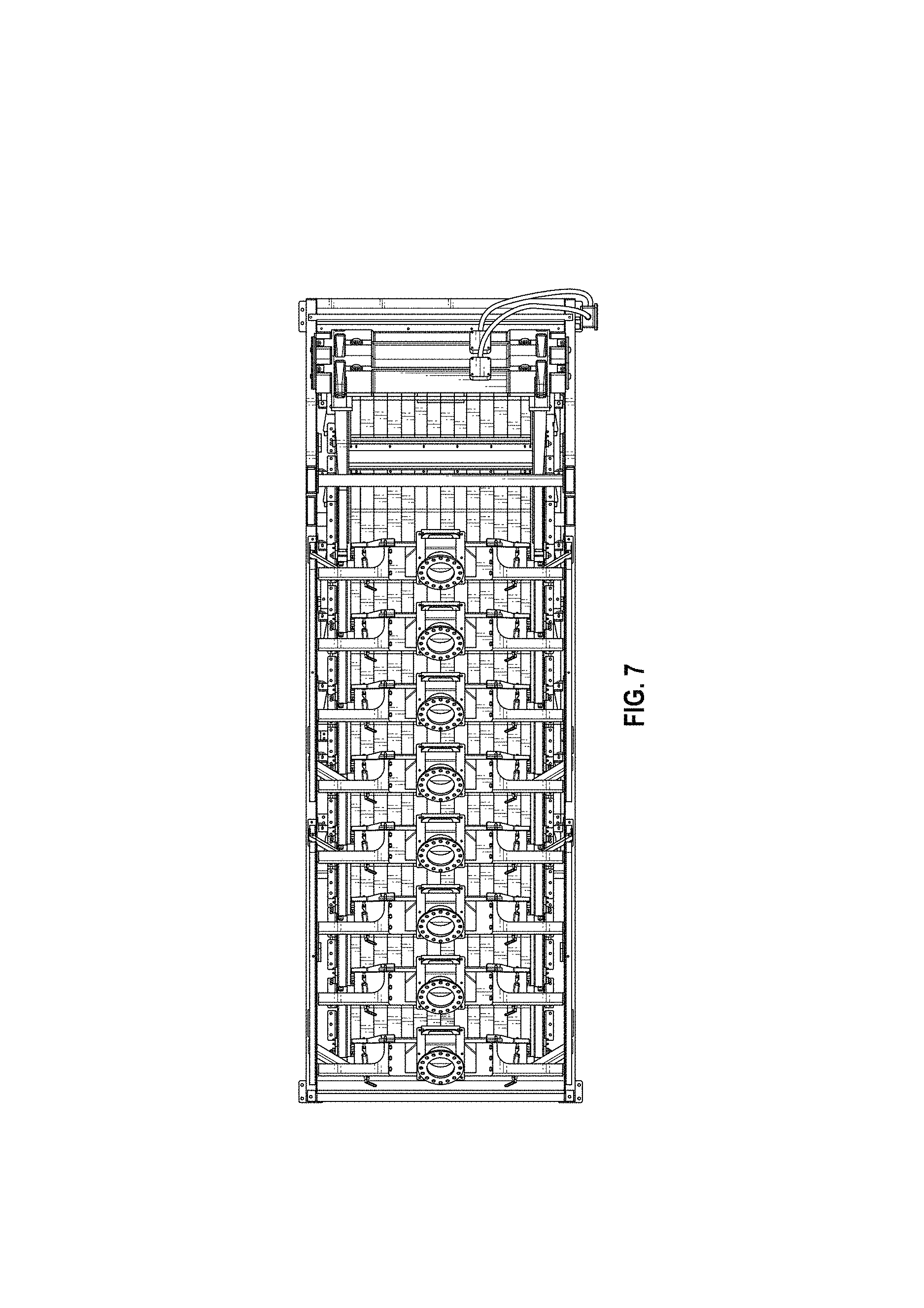
FIG. 7 is a top view thereof; and,
FIG. 8 is a bottom view thereof.
* * * * *
D00000
D00001
D00002
D00003
D00004
D00005
D00006
D00007
XML
uspto.report is an independent third-party trademark research tool that is not affiliated, endorsed, or sponsored by the United States Patent and Trademark Office (USPTO) or any other governmental organization. The information provided by uspto.report is based on publicly available data at the time of writing and is intended for informational purposes only.
While we strive to provide accurate and up-to-date information, we do not guarantee the accuracy, completeness, reliability, or suitability of the information displayed on this site. The use of this site is at your own risk. Any reliance you place on such information is therefore strictly at your own risk.
All official trademark data, including owner information, should be verified by visiting the official USPTO website at www.uspto.gov. This site is not intended to replace professional legal advice and should not be used as a substitute for consulting with a legal professional who is knowledgeable about trademark law.