Nasal dilator
Alexander , et al.
U.S. patent number D852,952 [Application Number D/615,047] was granted by the patent office on 2019-07-02 for nasal dilator. This patent grant is currently assigned to SIMPLICITY, LLC. The grantee listed for this patent is Simplicity, LLC. Invention is credited to Ian J. Alexander, Brian D. Owens.


View All Diagrams
| United States Patent | D852,952 |
| Alexander , et al. | July 2, 2019 |
Nasal dilator
Claims
CLAIM The ornamental design for a nasal dilator, as shown and described.
| Inventors: | Alexander; Ian J. (Boeme, TX), Owens; Brian D. (Plano, TX) | ||||||||||
|---|---|---|---|---|---|---|---|---|---|---|---|
| Applicant: |
|
||||||||||
| Assignee: | SIMPLICITY, LLC (Springville,
UT) |
||||||||||
| Appl. No.: | D/615,047 | ||||||||||
| Filed: | August 25, 2017 |
Related U.S. Patent Documents
| Application Number | Filing Date | Patent Number | Issue Date | ||
|---|---|---|---|---|---|
| 29496118 | Nov 22, 2016 | D772408 | |||
| Current U.S. Class: | D24/135 |
| Current International Class: | 2402 |
| Field of Search: | ;D24/135,112,130,133,140,147,149 ;600/200,202,184,220-227,201,203,210-218 ;606/191-200 ;D28/57 |
References Cited [Referenced By]
U.S. Patent Documents
| D247512 | March 1978 | Sandler |
| D275227 | August 1984 | Garner |
| 6010520 | January 2000 | Pattison |
| D485358 | January 2004 | Woo |
| D586914 | February 2009 | DaSilva |
| D588747 | March 2009 | Wittke-Kothe |
| D631962 | February 2011 | Dorman |
| D648021 | November 2011 | Dorman |
| D652519 | January 2012 | Miles et al. |
| D652921 | January 2012 | Miles et al. |
| D652922 | January 2012 | Miles et al. |
| D666292 | August 2012 | Miles et al. |
| D666293 | August 2012 | Miles et al. |
| D666294 | August 2012 | Miles et al. |
| D772408 | November 2016 | Alexander |
| D792589 | July 2017 | Alexander |
| D802127 | November 2017 | Alexander |
| D833607 | November 2018 | Aradono |
| D834188 | November 2018 | Alexander |
| 2015/0066071 | March 2015 | Alexander |
Assistant Examiner: Booker; Mark
Attorney, Agent or Firm: Goodhue, Coleman & Owens, P.C.
Description
FIG. 1 is a perspective view of a nasal dilator showing our new design;
FIG. 2 is an enlarged view of the left side of the nasal dilator shown in FIG. 1 taken along line 2;
FIG. 3 is an enlarged view of the right side of the nasal dilator shown in FIG. 1 taken along line 3;
FIG. 4 is a front view of the nasal dilator shown in FIG. 1;
FIG. 5 is an enlarged view of the left side of the nasal dilator shown in FIG. 4 taken along line 5;
FIG. 6 is an enlarged view of the right side of the nasal dilator shown in FIG. 4 taken along line 6;
FIG. 7 is a back view of the nasal dilator shown in FIG. 1;
FIG. 8 is an enlarged view of the left side of the nasal dilator shown in FIG. 7 taken along line 8;
FIG. 9 is an enlarged view of the right side of the nasal dilator shown in FIG. 7 taken along line 9;
FIG. 10 is a top view of the nasal dilator shown in FIG. 1;
FIG. 11 is an enlarged view of the left side of the nasal dilator shown in FIG. 10 taken along line 11;
FIG. 12 is an enlarged view of the right side of the nasal dilator shown in FIG. 10 taken along line 12;
FIG. 13 is an enlarged end view of the left side of the nasal dilator shown in FIG. 1;
FIG. 14 is an enlarged end view of the right side of the nasal dilator shown in FIG. 1;
FIG. 15 is a perspective view of a nasal dilator showing another one of our new designs;
FIG. 16 is an enlarged view of the left side of the nasal dilator shown in FIG. 15 taken along line 16;
FIG. 17 is an enlarged view of the right side of the nasal dilator shown in FIG. 15 taken along line 17;
FIG. 18 is a front view of the nasal dilator shown in FIG. 15;
FIG. 19 is an enlarged view of the left side of the nasal dilator shown in FIG. 18 taken along line 19;
FIG. 20 is an enlarged view of the right side of the nasal dilator shown in FIG. 18 taken along line 20;
FIG. 21 is a back view of the nasal dilator shown in FIG. 15;
FIG. 22 is an enlarged view of the left side of the nasal dilator shown in FIG. 21 taken along line 22;
FIG. 23 is an enlarged view of the right side of the nasal dilator shown in FIG. 21 taken along line 23;
FIG. 24 is a top view of the nasal dilator shown in FIG. 15;
FIG. 25 is an enlarged view of the left side of the nasal dilator shown in FIG. 24 taken along line 25;
FIG. 26 is an enlarged view of the right side of the nasal dilator shown in FIG. 24 taken along line 26;
FIG. 27 is an enlarged end view of the right side of the nasal dilator shown in FIG. 15;
FIG. 28 is an enlarged end view of the left side of the nasal dilator shown in FIG. 15;
FIG. 29 is a perspective view of a nasal dilator showing another one of our new designs;
FIG. 30 is an enlarged view of the left side of the nasal dilator shown in FIG. 29 taken along line 30;
FIG. 31 is an enlarged view of the right side of the nasal dilator shown in FIG. 29 taken along line 31;
FIG. 32 is a front view of the nasal dilator shown in FIG. 29;
FIG. 33 is an enlarged view of the left side of the nasal dilator shown in FIG. 32 taken along line 33;
FIG. 34 is an enlarged view of the right side of the nasal dilator shown in FIG. 32 taken along line 34;
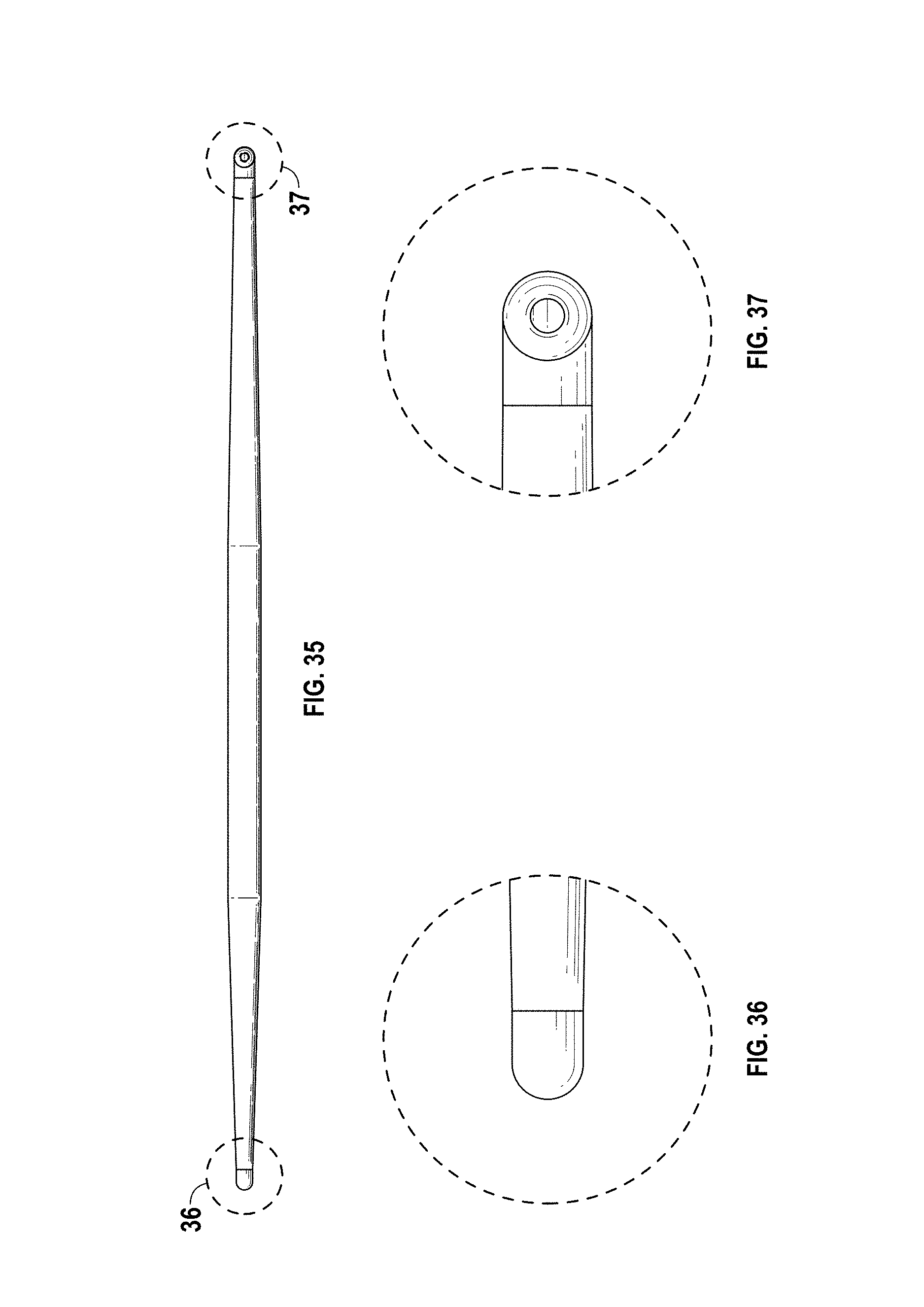
FIG. 35 is a back view of the nasal dilator shown in FIG. 29;
FIG. 36 is an enlarged view of the left side of the nasal dilator shown in FIG. 35 taken along line 36;
FIG. 37 is an enlarged view of the right side of the nasal dilator shown in FIG. 35 taken along line 37;
FIG. 38 is a top view of the nasal dilator shown in FIG. 29;
FIG. 39 is an enlarged view of the left side of the nasal dilator shown in FIG. 38 taken along line 39;
FIG. 40 is an enlarged view of the right side of the nasal dilator shown in FIG. 38 taken along line 40;
FIG. 41 is an enlarged end view of the right side of the nasal dilator shown in FIG. 29;
FIG. 42 is an enlarged end view of the left side of the nasal dilator shown in FIG. 29;
FIG. 43 is a cross-sectional view of the left side of the nasal dilator shown in FIG. 30 taken along line 43-43; and,
FIG. 44 is a cross-sectional view of the right side of the nasal dilator shown in FIG. 31 taken along line 44-44.
* * * * *
D00000
D00001
D00002
D00003
D00004
D00005
D00006
D00007
D00008
D00009
D00010
D00011
D00012

D00013
D00014

D00015

XML
uspto.report is an independent third-party trademark research tool that is not affiliated, endorsed, or sponsored by the United States Patent and Trademark Office (USPTO) or any other governmental organization. The information provided by uspto.report is based on publicly available data at the time of writing and is intended for informational purposes only.
While we strive to provide accurate and up-to-date information, we do not guarantee the accuracy, completeness, reliability, or suitability of the information displayed on this site. The use of this site is at your own risk. Any reliance you place on such information is therefore strictly at your own risk.
All official trademark data, including owner information, should be verified by visiting the official USPTO website at www.uspto.gov. This site is not intended to replace professional legal advice and should not be used as a substitute for consulting with a legal professional who is knowledgeable about trademark law.