Cutting insert
Kobayashi , et al.
U.S. patent number D852,246 [Application Number D/674,333] was granted by the patent office on 2019-06-25 for cutting insert. This patent grant is currently assigned to Mitsubishi Hitachi Tool Engineering, Ltd.. The grantee listed for this patent is Mitsubishi Hitachi Tool Engineering, Ltd.. Invention is credited to Yoshiyuki Kobayashi, Hayato Takahashi, Shoujirou Touma.

| United States Patent | D852,246 |
| Kobayashi , et al. | June 25, 2019 |
Cutting insert
Claims
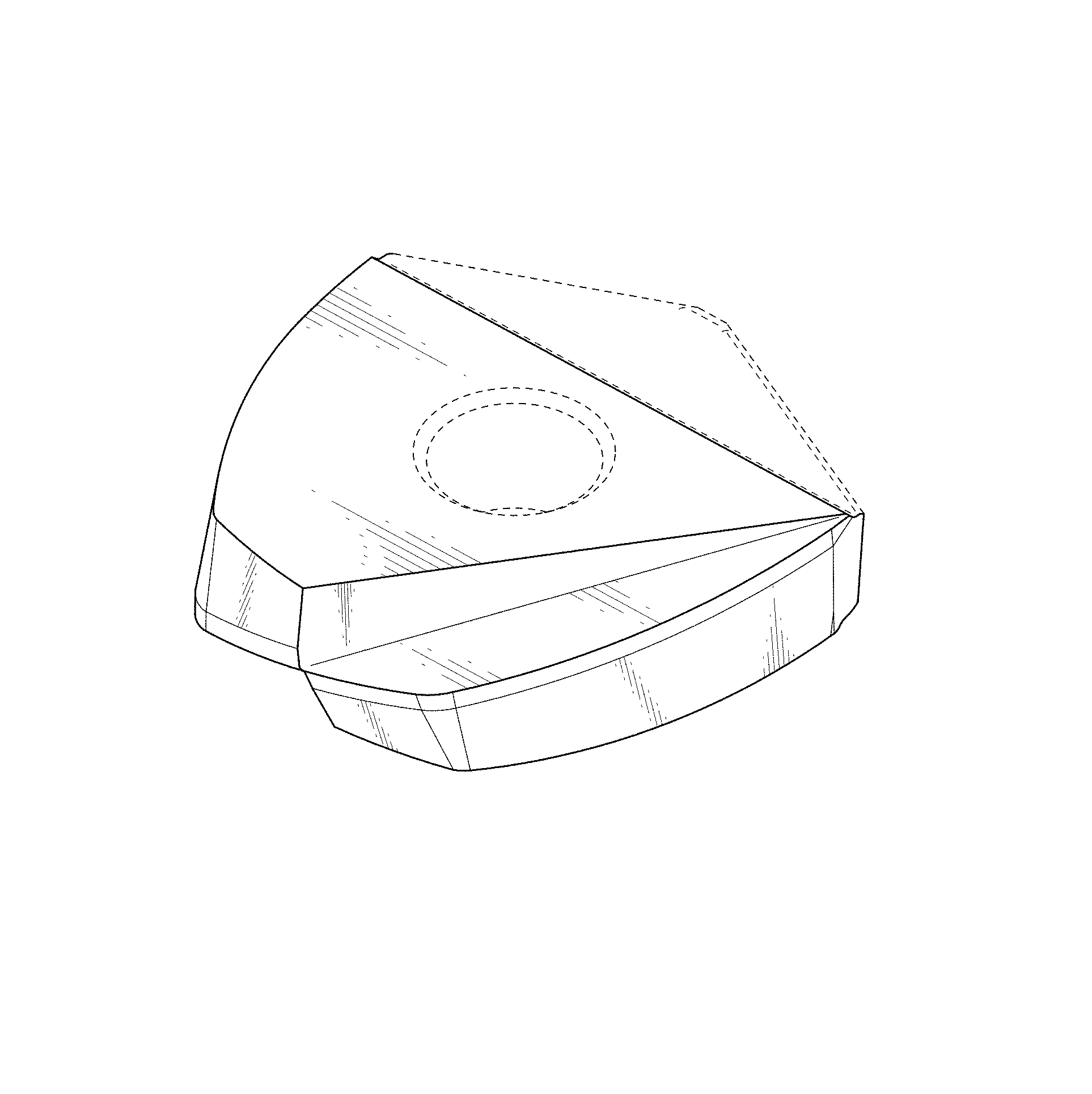
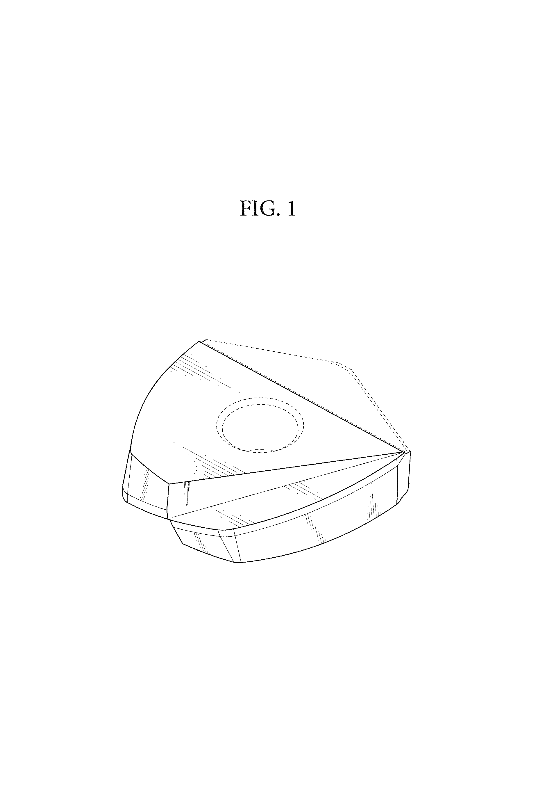
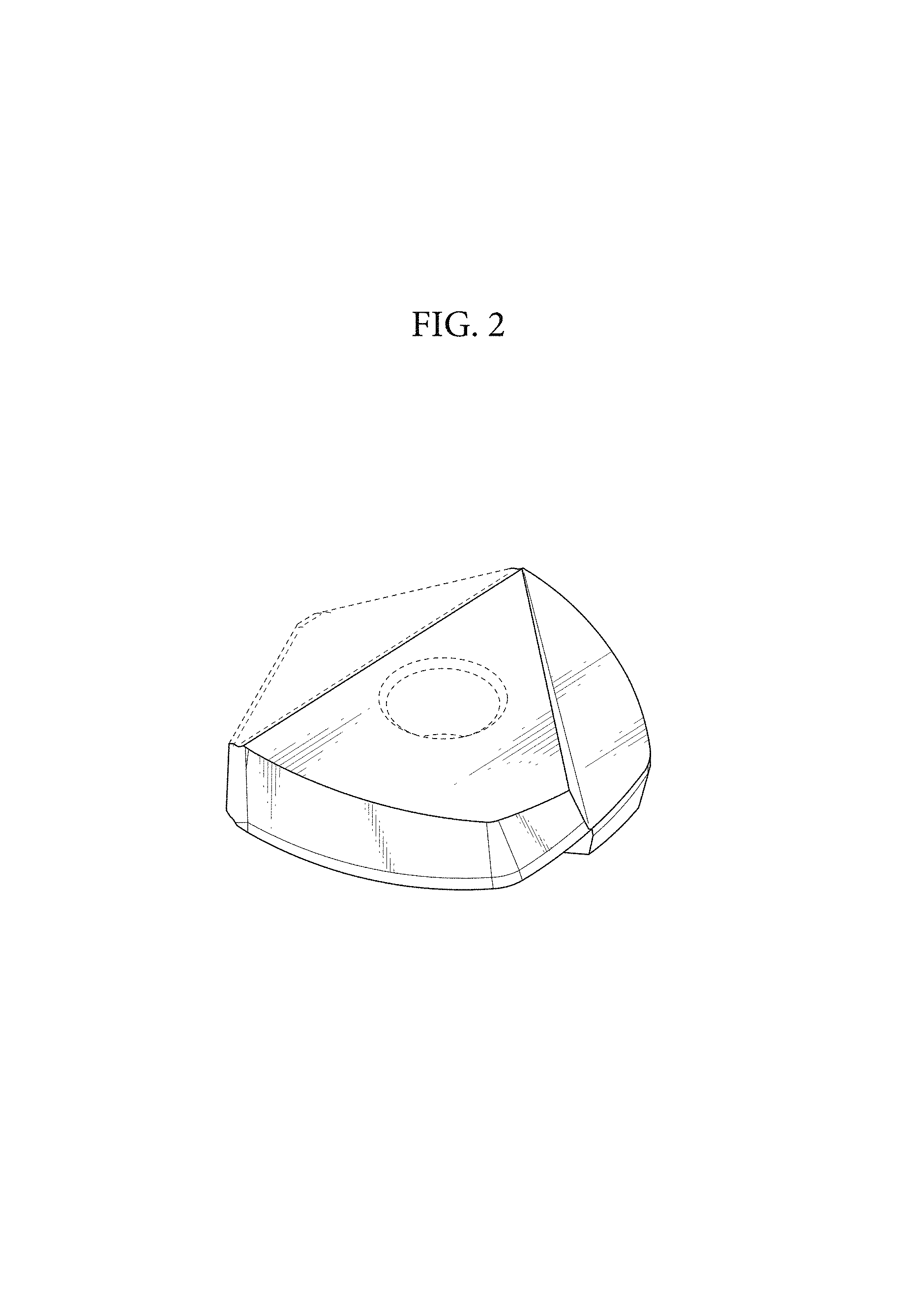
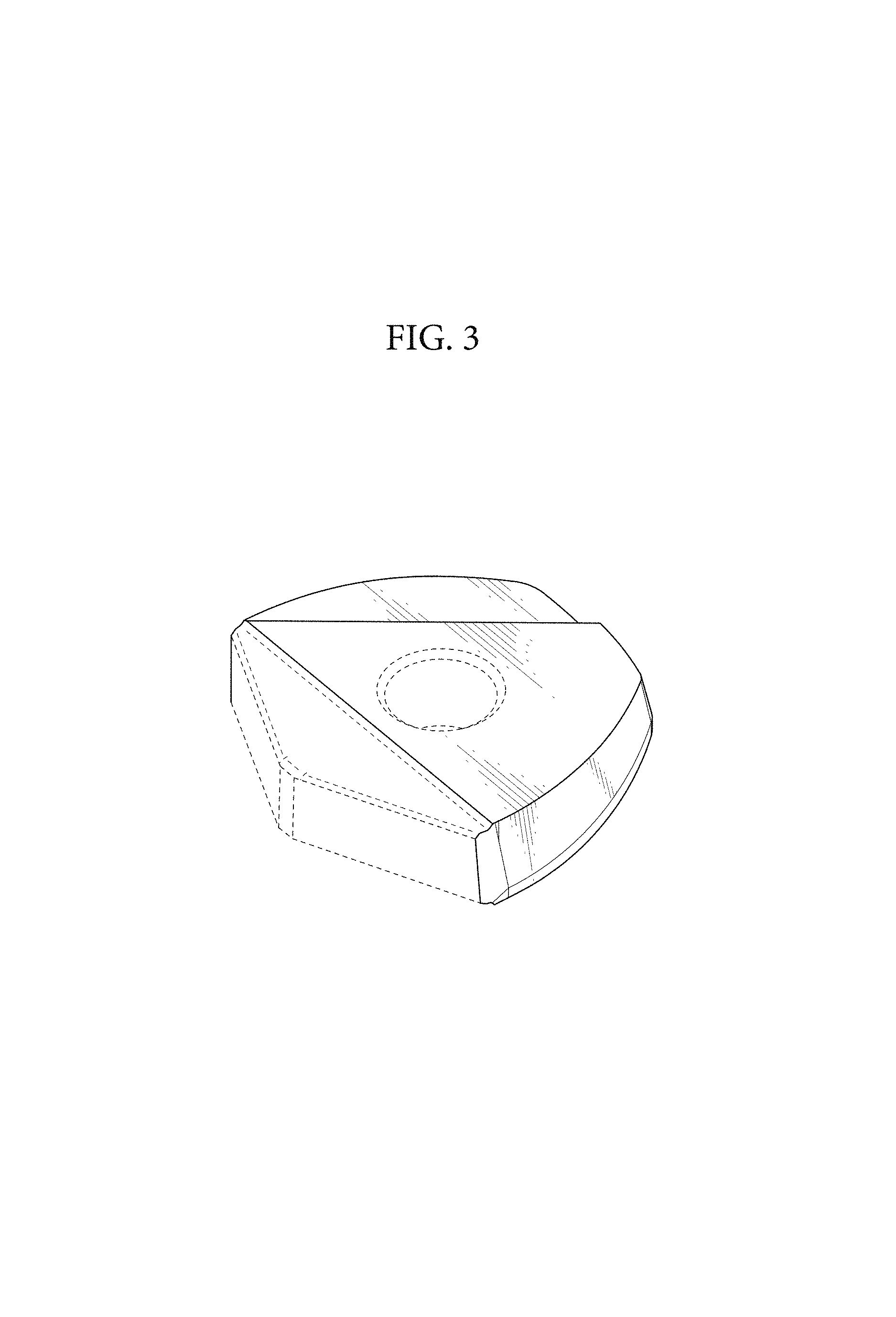
CLAIM The ornamental design for a cutting insert, as shown and described.
| Inventors: | Kobayashi; Yoshiyuki (Chiba, JP), Takahashi; Hayato (Chiba, JP), Touma; Shoujirou (Chiba, JP) | ||||||||||
|---|---|---|---|---|---|---|---|---|---|---|---|
| Applicant: |
|
||||||||||
| Assignee: | Mitsubishi Hitachi Tool
Engineering, Ltd. (Tokyo, JP) |
||||||||||
| Appl. No.: | D/674,333 | ||||||||||
| Filed: | December 20, 2018 |
Related U.S. Patent Documents
| Application Number | Filing Date | Patent Number | Issue Date | ||
|---|---|---|---|---|---|
| 29594205 | Feb 16, 2017 | ||||
Foreign Application Priority Data
| Nov 25, 2016 [JP] | 2016-025665 | |||
| Nov 25, 2016 [JP] | 2016-025666 | |||
| Nov 25, 2016 [JP] | 2016-025667 | |||
| Nov 25, 2016 [JP] | 2016-025668 | |||
| Current U.S. Class: | D15/139 |
| Current International Class: | 1509 |
| Field of Search: | ;D8/20,70 ;D15/126,131,138,139,140 |
References Cited [Referenced By]
U.S. Patent Documents
| D341604 | November 1993 | Hessman |
| 5332338 | July 1994 | Satran et al. |
| D387072 | December 1997 | Ojanen |
| 6249950 | June 2001 | Brask et al. |
| 6334740 | January 2002 | Qvarth |
| D485852 | January 2004 | Arvidsson |
| D487281 | March 2004 | Roman et al. |
| 6857831 | February 2005 | Davis |
| 7168512 | January 2007 | Schuffenhauer et al. |
| D595322 | June 2009 | Sakata et al. |
| D595323 | June 2009 | Sakata et al. |
| D595751 | July 2009 | Sakata et al. |
| D633535 | March 2011 | Tanaka et al. |
| 8840344 | September 2014 | Stenman |
| D735254 | July 2015 | O'Malley et al. |
| D772319 | November 2016 | Nam |
| D822077 | July 2018 | Takahashi |
| 2003/0180103 | September 2003 | Nagaya et al. |
| 2008/0253847 | October 2008 | Nicholas |
| 2011/0299945 | December 2011 | Choi et al. |
| 2012/0087748 | April 2012 | Uno et al. |
| 2015/0352646 | December 2015 | Bhagath et al. |
| 2017/0008100 | January 2017 | Oikawa |
Other References
|
Mechanical Engineering Publication; Publisher The Daily Industrial News (Japan); Reference No. ISSN D451-9396; p. 61; Publication date Feb. 1, 2016. cited by applicant. |
Primary Examiner: Palasik; Patricia A
Attorney, Agent or Firm: Banner & Witcoff, Ltd.
Description
FIG. 1 is a perspective view of a cutting insert showing our new design;
FIG. 2 is a perspective view thereof;
FIG. 3 is a perspective view thereof;
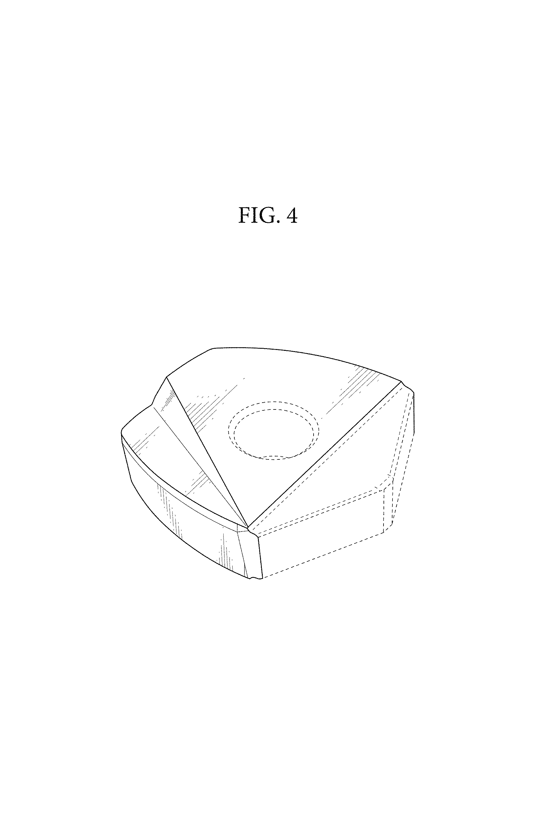
FIG. 4 is a perspective view thereof;
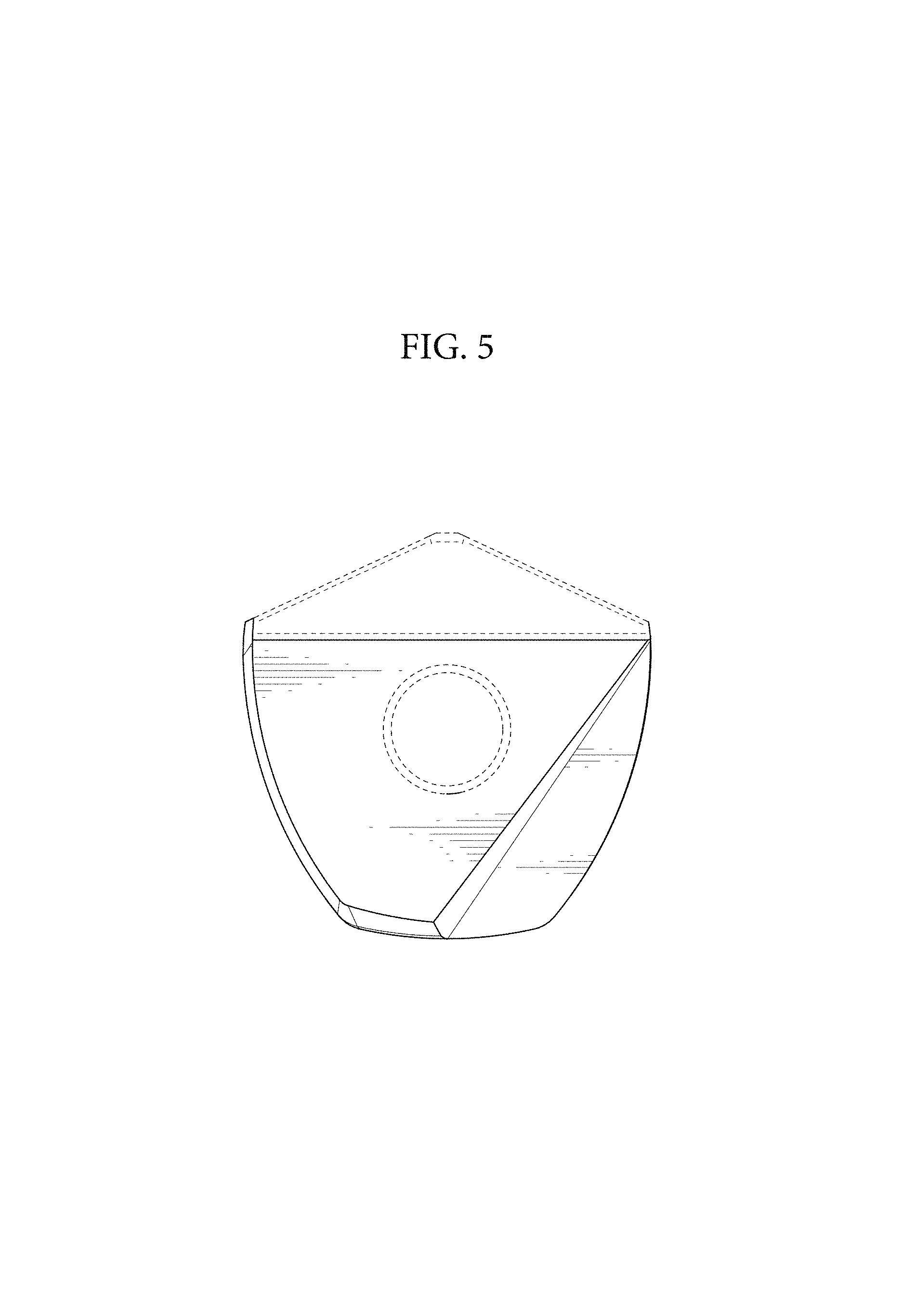
FIG. 5 is a front elevation view thereof; the rear elevation view is identical to the front elevation view;
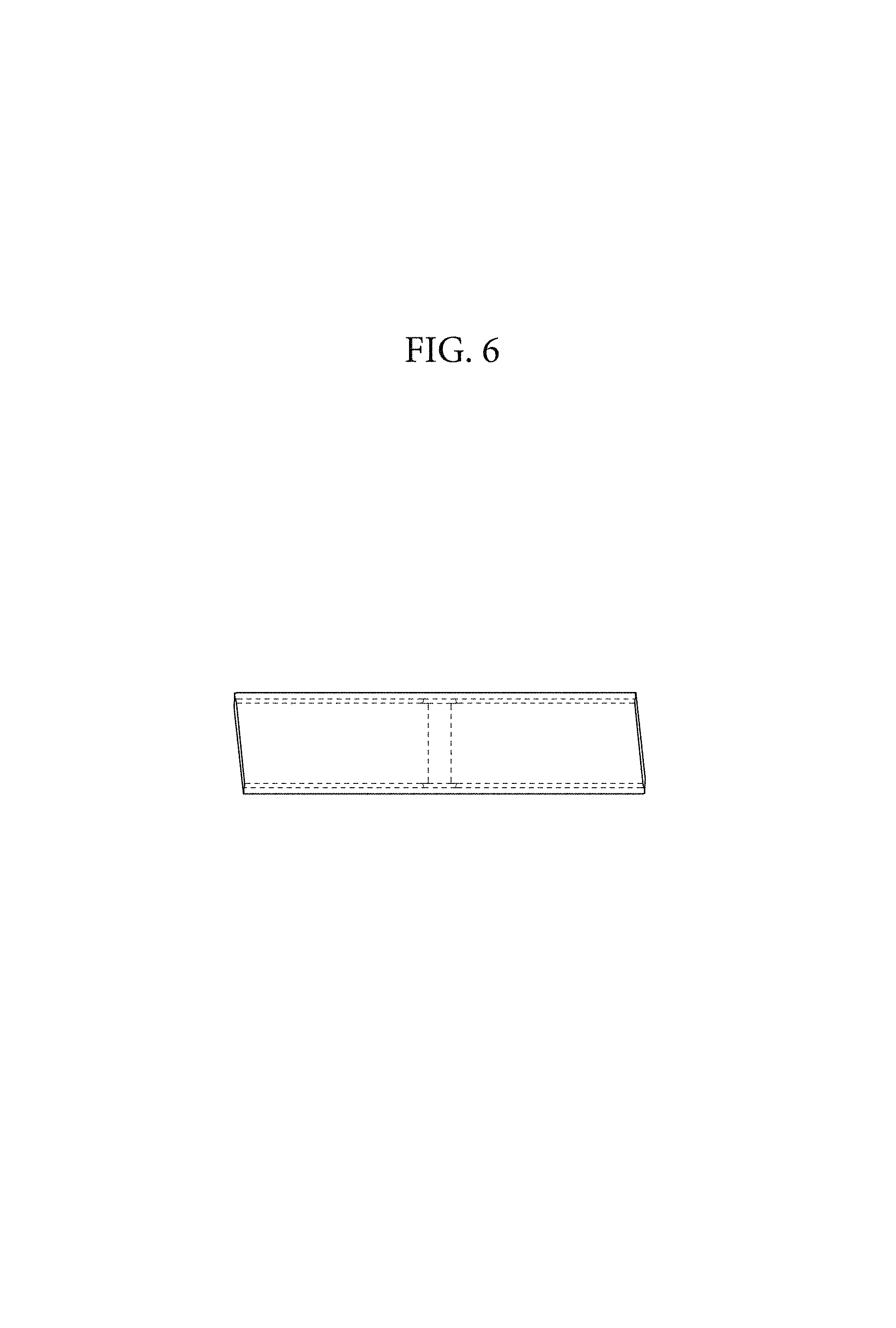
FIG. 6 is a top plan view thereof;
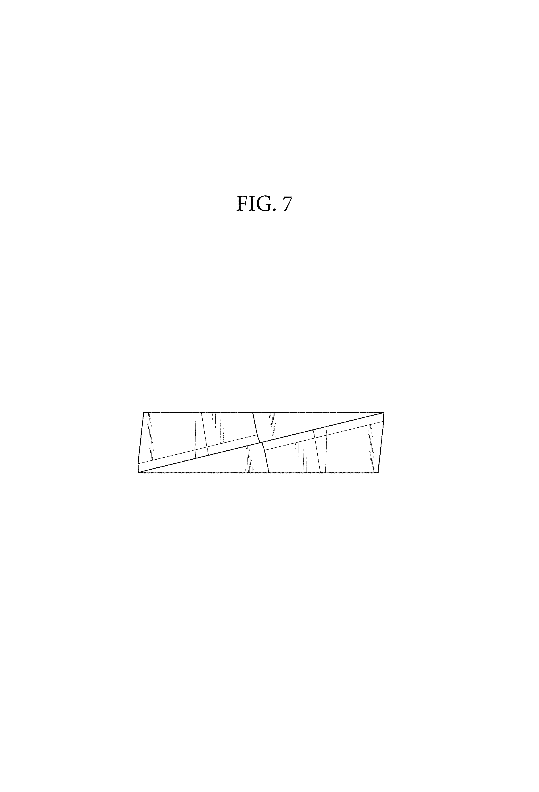
FIG. 7 is a bottom plan view thereof; and,
FIG. 8 is a right side elevation view thereof; a left side elevation view is identical to the right side elevation view.
The broken lines shown in the drawings illustrate portions of the cutting insert that form no part of claimed design.
* * * * *
D00000
D00001
D00002
D00003
D00004
D00005
D00006
D00007
D00008
XML
uspto.report is an independent third-party trademark research tool that is not affiliated, endorsed, or sponsored by the United States Patent and Trademark Office (USPTO) or any other governmental organization. The information provided by uspto.report is based on publicly available data at the time of writing and is intended for informational purposes only.
While we strive to provide accurate and up-to-date information, we do not guarantee the accuracy, completeness, reliability, or suitability of the information displayed on this site. The use of this site is at your own risk. Any reliance you place on such information is therefore strictly at your own risk.
All official trademark data, including owner information, should be verified by visiting the official USPTO website at www.uspto.gov. This site is not intended to replace professional legal advice and should not be used as a substitute for consulting with a legal professional who is knowledgeable about trademark law.