Optical scanner
Memke , et al.
U.S. patent number D851,644 [Application Number D/670,956] was granted by the patent office on 2019-06-18 for optical scanner. This patent grant is currently assigned to HAND HELD PRODUCTS, INC.. The grantee listed for this patent is Hand Held Products, Inc.. Invention is credited to John S. Bandringa, William Herweh, III, Roger Jackson, Matthew McElvogue, David K. Memke, Rajat Shail, Churu Yun, Tim Zurmoehle.

| United States Patent | D851,644 |
| Memke , et al. | June 18, 2019 |
Optical scanner
Claims
CLAIM The ornamental design for an optical scanner, as shown in the accompanying drawings and described above.
| Inventors: | Memke; David K. (Bainbridge Island, WA), Bandringa; John S. (Everette, WA), Jackson; Roger (Lake Forest Park, WA), Zurmoehle; Tim (Seattle, WA), Herweh, III; William (Seattle, WA), Yun; Churu (Seattle, WA), McElvogue; Matthew (Seattle, WA), Shail; Rajat (Chicago, IL) | ||||||||||
|---|---|---|---|---|---|---|---|---|---|---|---|
| Applicant: |
|
||||||||||
| Assignee: | HAND HELD PRODUCTS, INC. (Fort
Mills, SC) |
||||||||||
| Appl. No.: | D/670,956 | ||||||||||
| Filed: | November 21, 2018 |
Related U.S. Patent Documents
| Application Number | Filing Date | Patent Number | Issue Date | ||
|---|---|---|---|---|---|
| 29572896 | Aug 1, 2016 | D837215 | |||
| Current U.S. Class: | D14/428 |
| Current International Class: | 1402 |
| Field of Search: | ;D14/420,426-430,453,346,341,347,412,138 ;D13/107,184 ;358/473 ;235/462.43,462.45,462.47,462.48,462.44,462.46,487,472.01,472.02,145A,145R,462.21,462.42,462.01,462.35 ;D10/78,70 ;324/426 ;D3/273 ;710/73 ;D18/7 ;361/679,728,679.56 ;382/313,312,276,285-295,314-325 ;455/575.1,561,572 ;345/156,168,169,172,173,87 ;705/17,18,22-25 ;D26/45-51 ;D24/185,186 ;D8/68,315,80,105,107,300-303,307,321,29.1,29.2,61,70,75-77,81 ;348/47,49,E13.074 ;702/85,94,95,127,150-168,189 ;356/601-613,625-640 ;D28/13-18 ;34/97,99 ;D32/8,13 ;392/384,385 |
References Cited [Referenced By]
U.S. Patent Documents
| D248048 | May 1978 | Cousins |
| D251989 | May 1979 | Rizzuto |
| D253012 | September 1979 | Rakocy |
| D253253 | October 1979 | Rakocy |
| D257492 | November 1980 | Cousins |
| D262060 | November 1981 | Nagelkerke |
| D262062 | November 1981 | Nagelkerke |
| D263427 | March 1982 | McBrien |
| D265136 | June 1982 | Madl |
| D265767 | August 1982 | Stewart |
| 4418732 | December 1983 | Kolonia |
| D273359 | April 1984 | Kolonia |
| D274153 | June 1984 | Nagelkerke |
| D278085 | March 1985 | Rittenhouse |
| D286209 | October 1986 | Camens |
| D288726 | March 1987 | Muller |
| D290174 | June 1987 | Tsuji |
| 4904847 | February 1990 | Kosaka |
| D317154 | May 1991 | Allgeier |
| D341302 | November 1993 | Ware |
| D350413 | September 1994 | Feil |
| 5590475 | January 1997 | Andis |
| D386815 | November 1997 | Muller |
| D398073 | September 1998 | Kip |
| D398717 | September 1998 | Kling |
| D425662 | May 2000 | Cheung |
| D425663 | May 2000 | Greubel |
| D426023 | May 2000 | Elkerbout |
| D429028 | August 2000 | Muller |
| D432715 | October 2000 | Harris |
| D436200 | January 2001 | Cheong |
| D441112 | April 2001 | Krieger |
| D456808 | May 2002 | Fitch |
| D491303 | June 2004 | Shen |
| 6751886 | June 2004 | Chang |
| D500155 | December 2004 | Lee |
| 6889445 | May 2005 | Varona |
| D526731 | August 2006 | Cheung |
| 7229189 | June 2007 | Parker |
| D549863 | August 2007 | Garrity |
| D571808 | June 2008 | Dorr |
| D584438 | January 2009 | Crawford |
| D586037 | February 2009 | Smith |
| D599182 | September 2009 | Baxter |
| D605796 | December 2009 | Crawford |
| D608856 | January 2010 | Dammkoehler |
| 7673804 | March 2010 | Hinson |
| D619442 | July 2010 | Chen |
| D656379 | March 2012 | Islas |
| D658961 | May 2012 | Islas |
| D662241 | June 2012 | Tschopp |
| D673706 | January 2013 | Inskeep |
| D673707 | January 2013 | Inskeep |
| D711029 | August 2014 | Schnell |
| D714453 | September 2014 | Mongin |
| D716126 | October 2014 | Dahlberg |
| D716492 | October 2014 | Dyson |
| D737489 | August 2015 | Russell |
| D737651 | September 2015 | Masalin |
| D742047 | October 2015 | Lee |
| D757361 | May 2016 | Gammack |
| D759870 | June 2016 | Hine |
| D760054 | June 2016 | Huttunen |
| D761075 | July 2016 | Masalin |
| D761632 | July 2016 | Masalin |
| D769098 | October 2016 | Huttunen |
| D788265 | May 2017 | Ho |
| D788341 | May 2017 | Inskeep |
| 9687058 | June 2017 | Atkinson |
| D791407 | July 2017 | Smith |
| D799295 | October 2017 | Huttunen |
| 9808066 | November 2017 | Moloney |
| D806211 | December 2017 | Bahler |
| D824060 | July 2018 | Kunzendorf |
| D824229 | July 2018 | Williams |
| 10019334 | July 2018 | Caballero |
| 2001/0045466 | November 2001 | Bontly |
| 2002/0043003 | April 2002 | Cruz |
| 2003/0223227 | December 2003 | Levine |
| 2006/0133089 | June 2006 | Reid |
| 2010/0308116 | December 2010 | Sani |
| 2013/0283631 | October 2013 | Moloney |
| 2015/0102109 | April 2015 | Huck |
| 2016/0154985 | June 2016 | Auger |
| 2016/0206077 | July 2016 | Stephens |
| 2018/0049532 | February 2018 | Hsu |
Attorney, Agent or Firm: Additon, Higgins & Pendleton, P.A.
Description
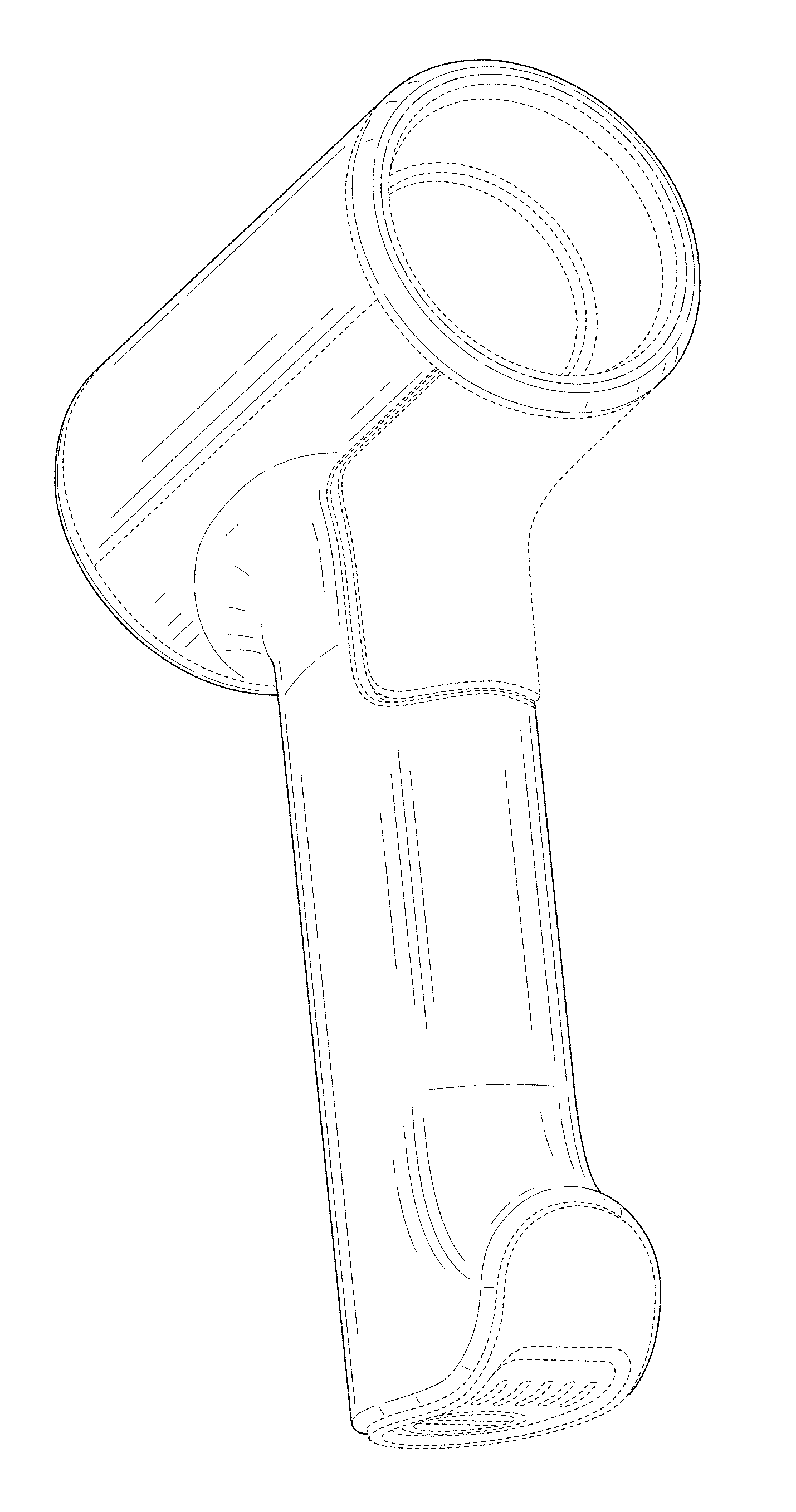
FIG. 1 is a front, lower left perspective view of an optical scanner in accordance with the present design.
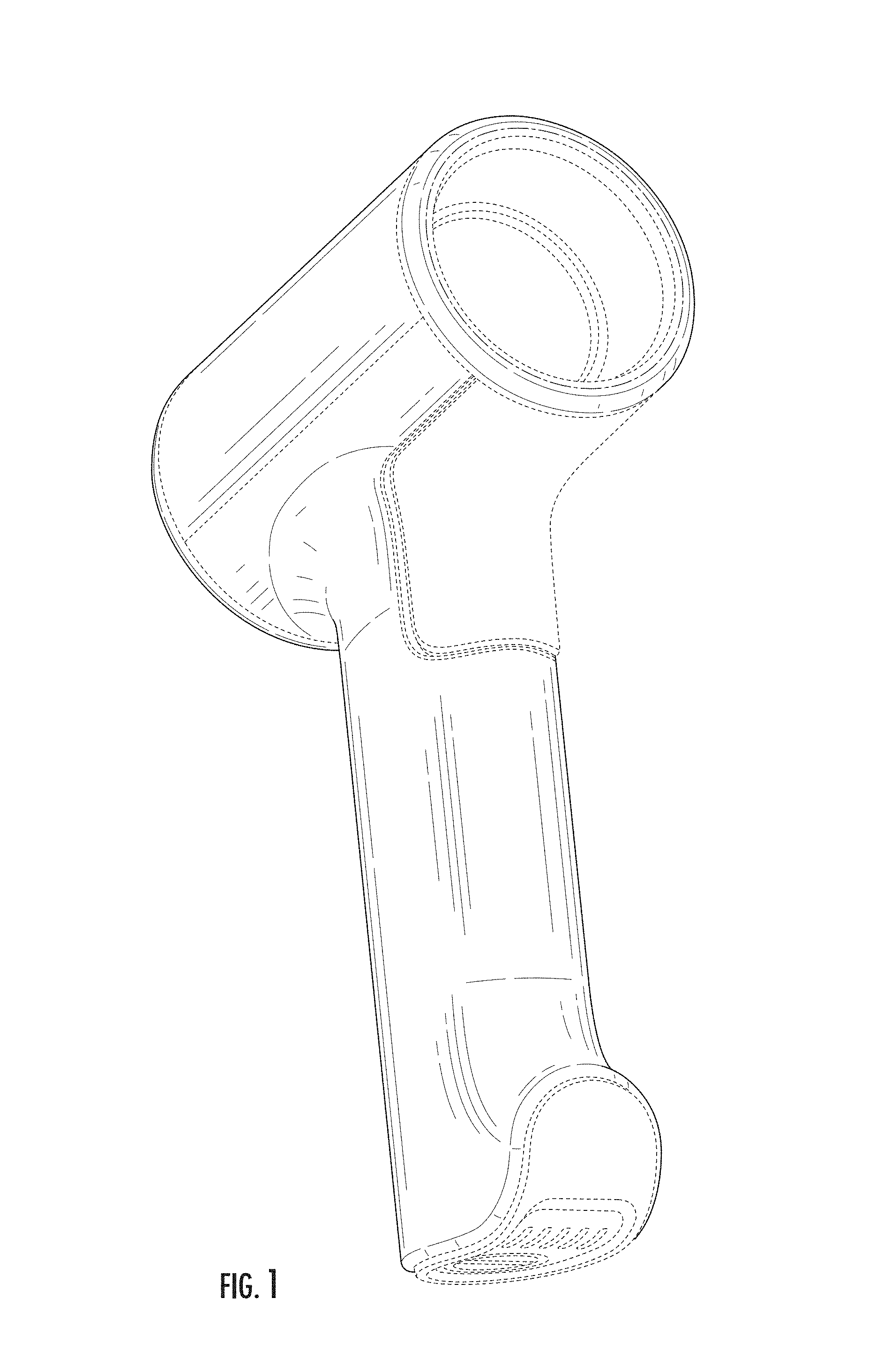
FIG. 2 is a front, upper right perspective view of the optical scanner of FIG. 1.
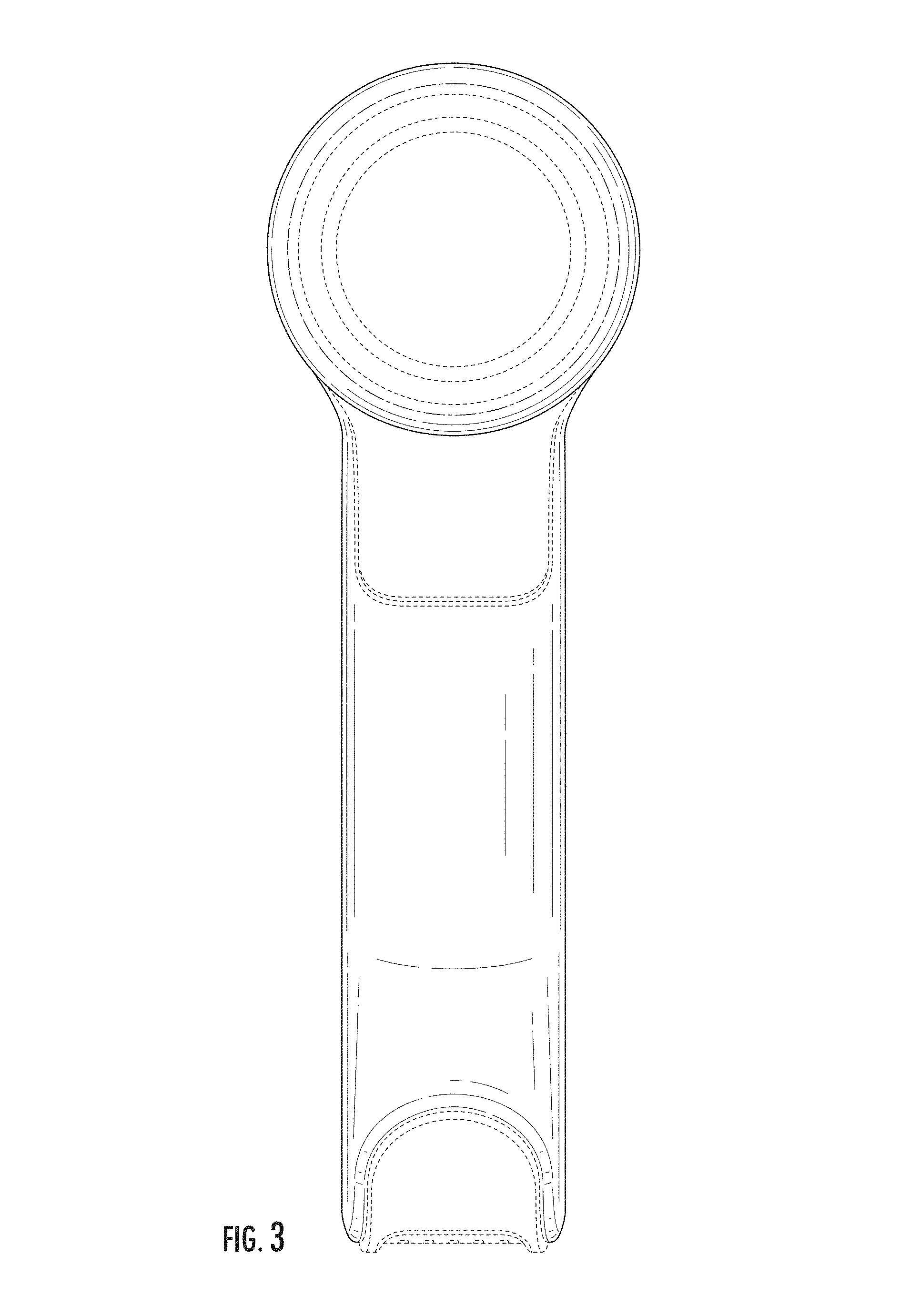
FIG. 3 is a front elevation view of the optical scanner of FIG. 1.
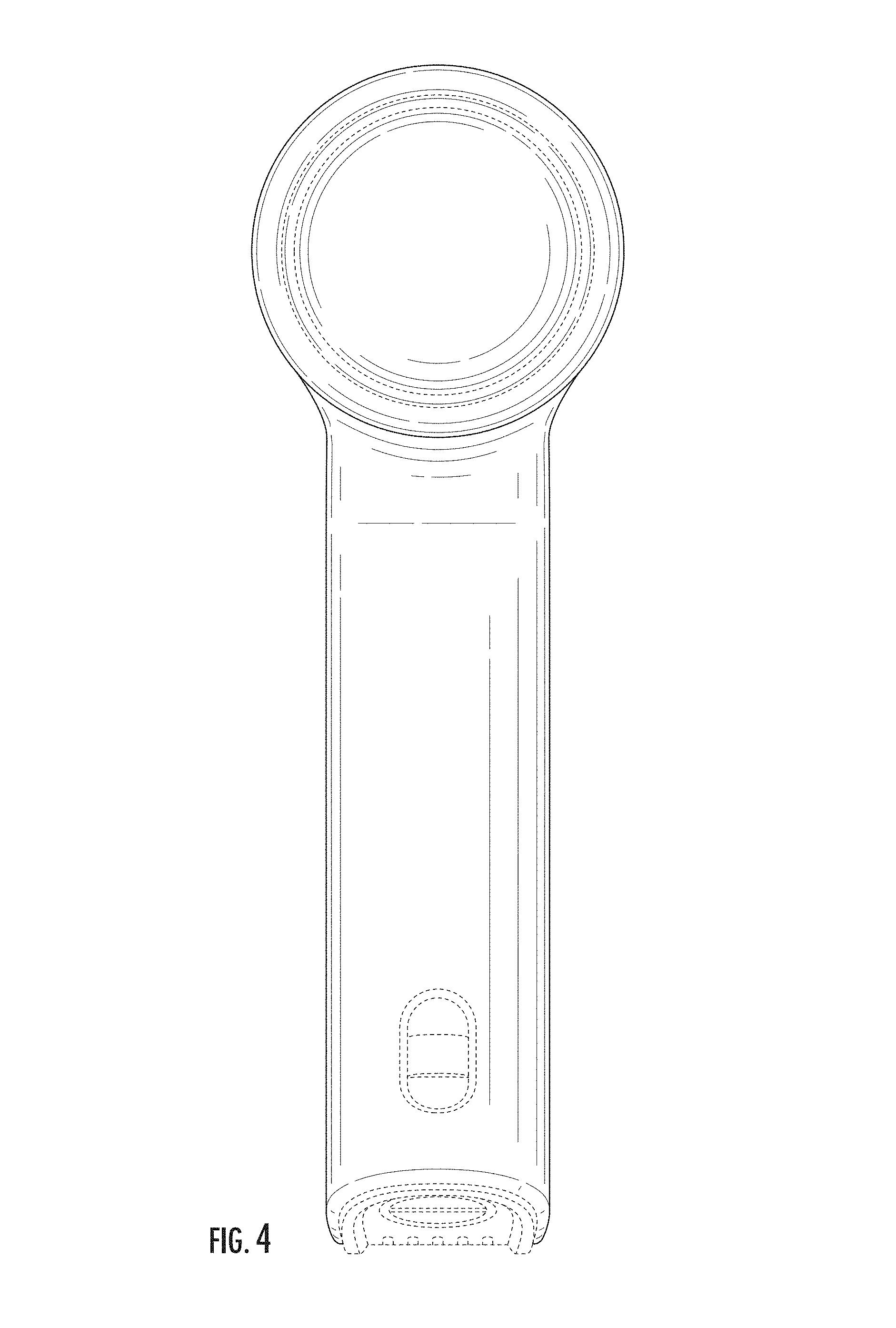
FIG. 4 is a rear elevation view of the optical scanner of FIG. 1.
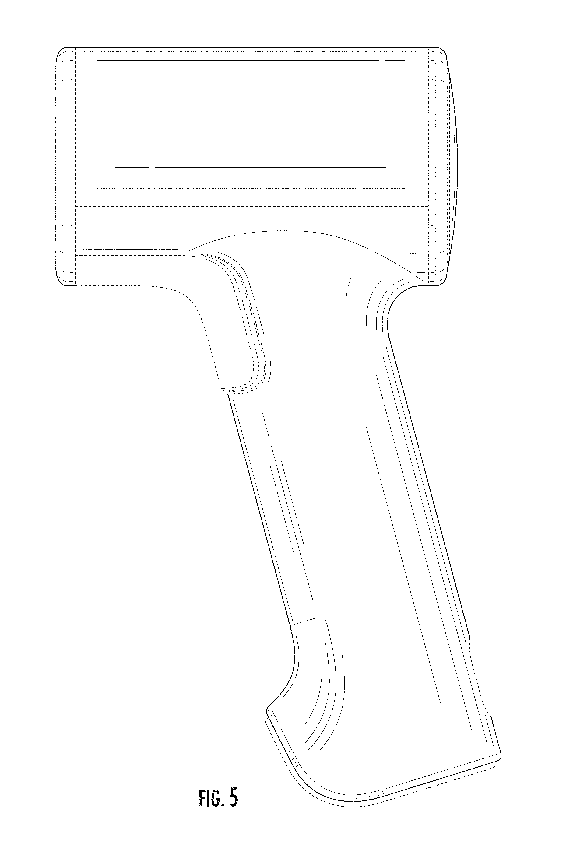
FIG. 5 is a right elevation view of the optical scanner of FIG. 1.
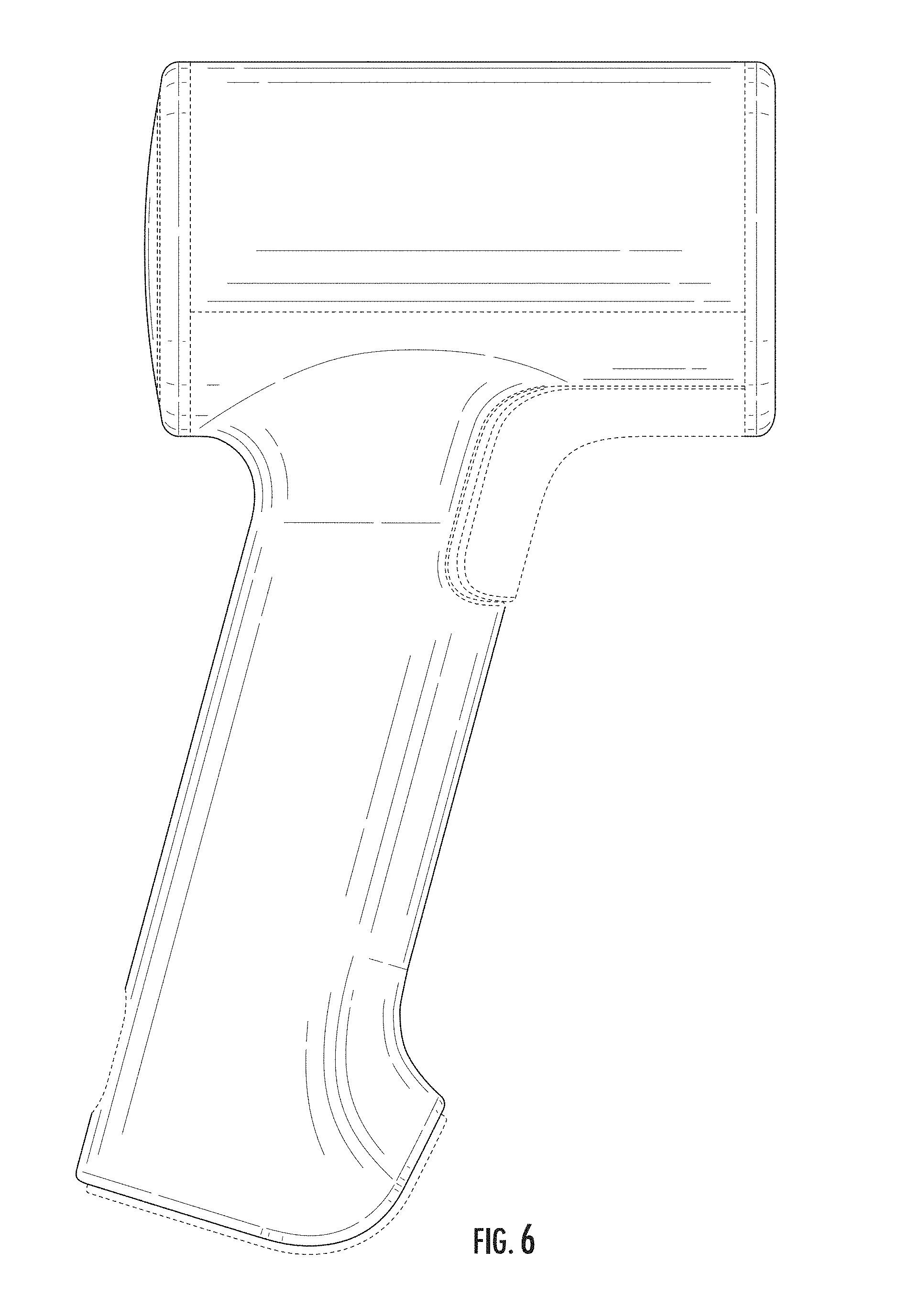
FIG. 6 is a left elevation view of the optical scanner of FIG. 1.
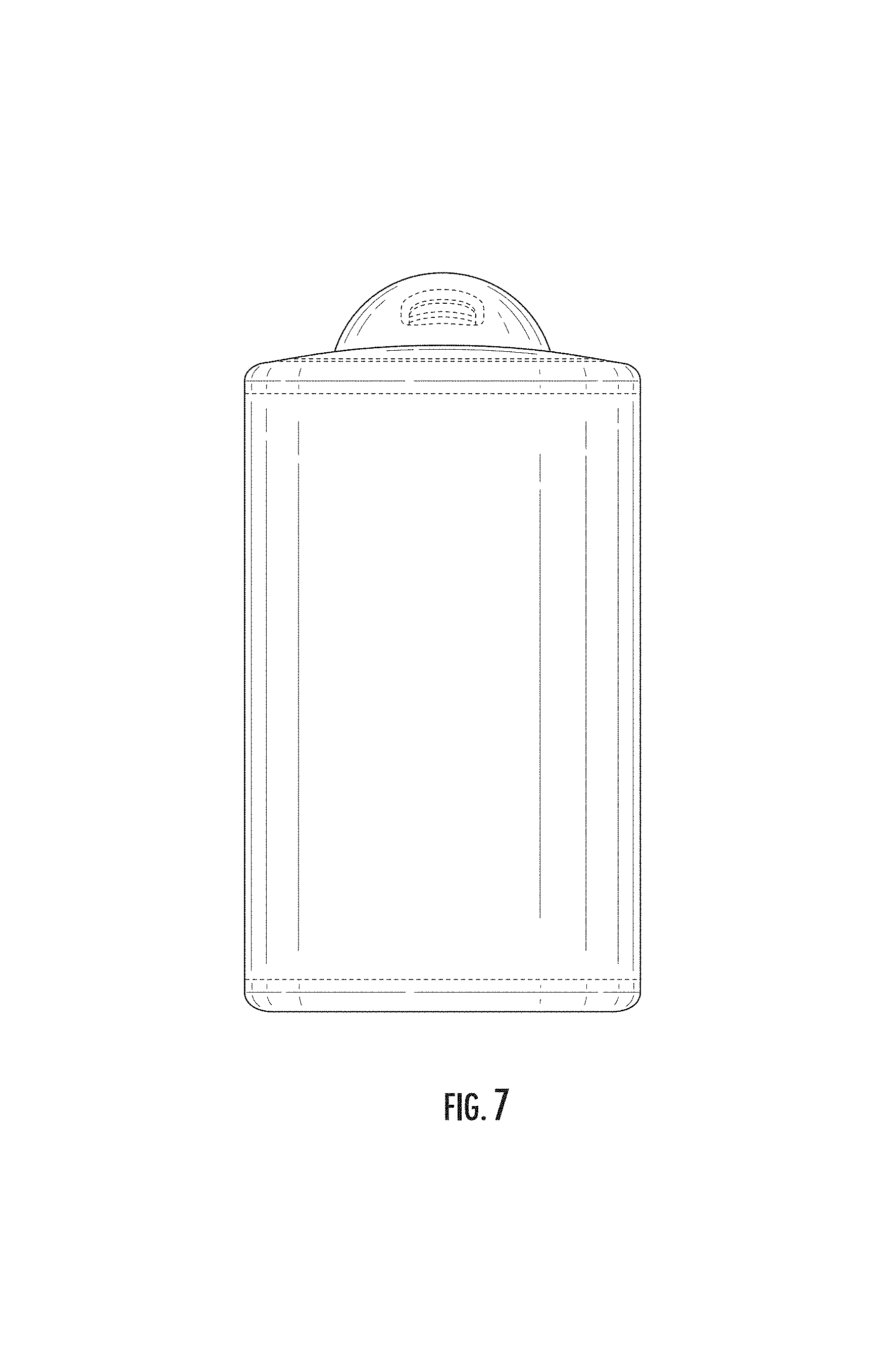
FIG. 7 is a top plan view of the optical scanner of FIG. 1; and,
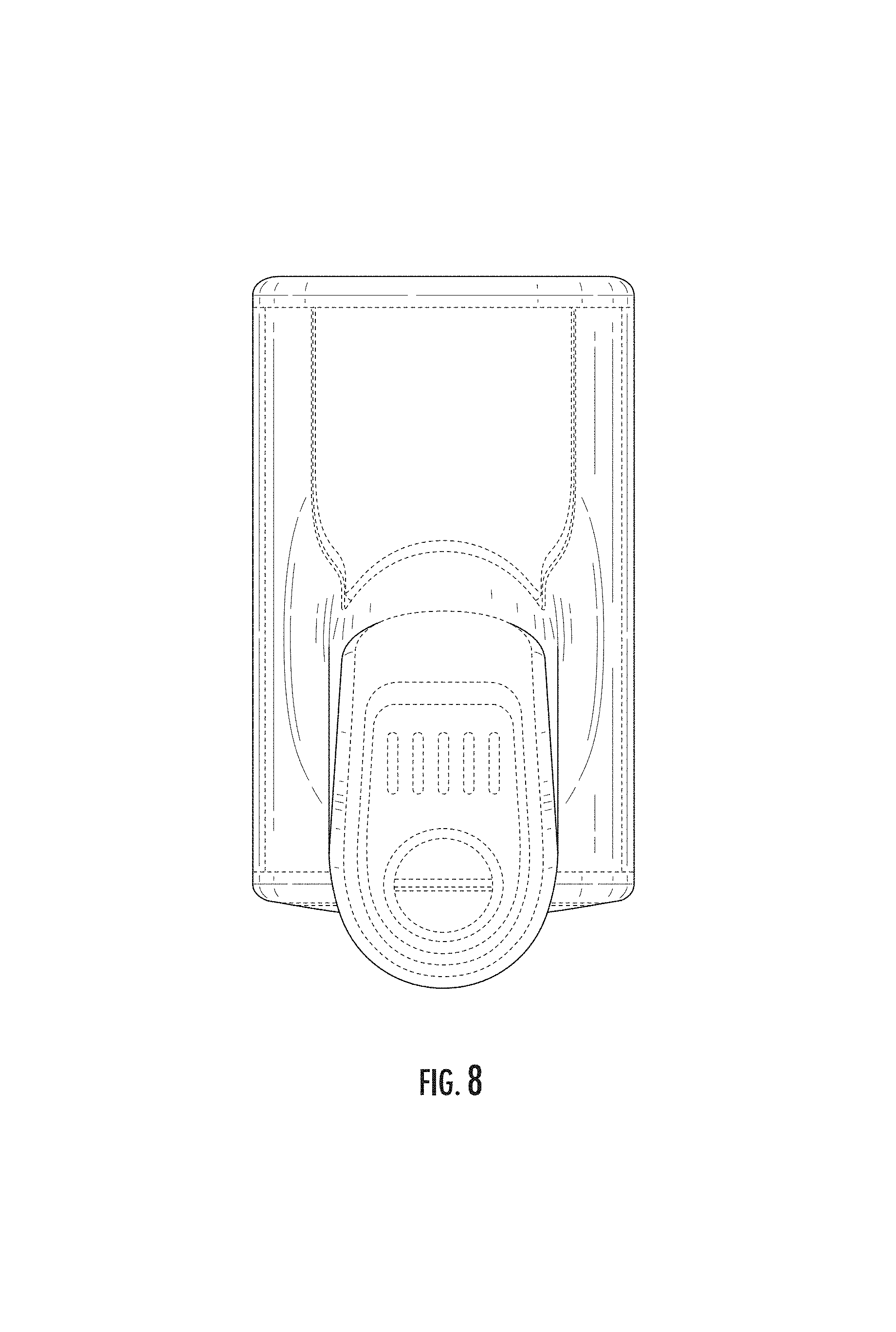
FIG. 8 is a bottom plan view of the optical scanner of FIG. 1.
The broken lines and unshaded portions contained within broken lines depict unclaimed features of the optical scanner that form no part of the claimed design but are shown for purposes of illustration. The dot-dash line depicts the boundary at which unclaimed portions terminate and claimed subject matter begins, and forms no part of the design claim.
* * * * *
D00000
D00001
D00002
D00003
D00004
D00005
D00006
D00007
D00008
XML
uspto.report is an independent third-party trademark research tool that is not affiliated, endorsed, or sponsored by the United States Patent and Trademark Office (USPTO) or any other governmental organization. The information provided by uspto.report is based on publicly available data at the time of writing and is intended for informational purposes only.
While we strive to provide accurate and up-to-date information, we do not guarantee the accuracy, completeness, reliability, or suitability of the information displayed on this site. The use of this site is at your own risk. Any reliance you place on such information is therefore strictly at your own risk.
All official trademark data, including owner information, should be verified by visiting the official USPTO website at www.uspto.gov. This site is not intended to replace professional legal advice and should not be used as a substitute for consulting with a legal professional who is knowledgeable about trademark law.