Trampoline tensioner
Seaman , et al.
U.S. patent number D851,190 [Application Number D/606,708] was granted by the patent office on 2019-06-11 for trampoline tensioner. This patent grant is currently assigned to Action Sports Equipment Pty Ltd.. The grantee listed for this patent is Action Sports Equipment Pty Ltd.. Invention is credited to Lee David Blattmann, Murray David Kirby Hunter, David Andrew Jones, Robert Brian Seaman.


| United States Patent | D851,190 |
| Seaman , et al. | June 11, 2019 |
Trampoline tensioner
Claims
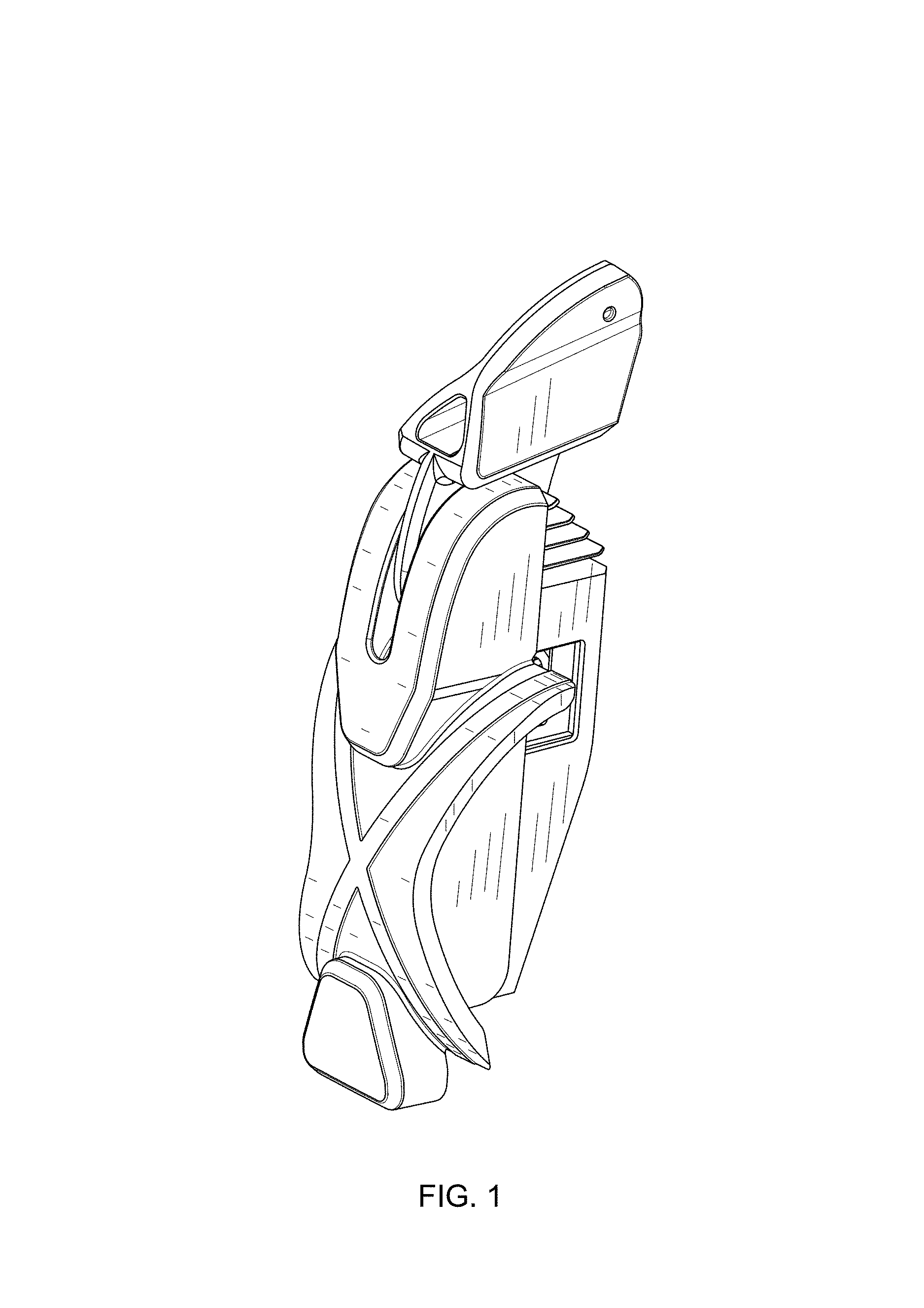
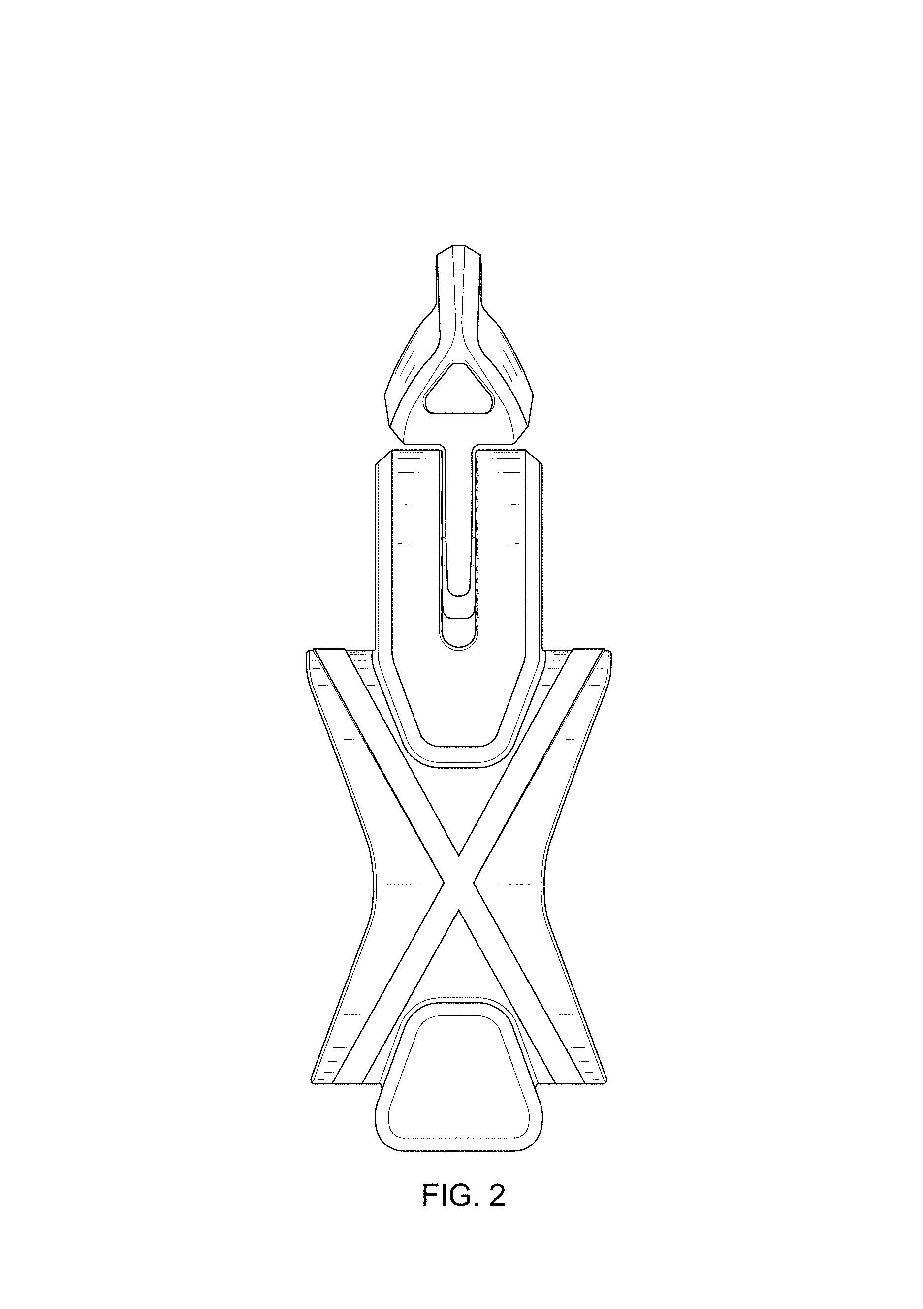
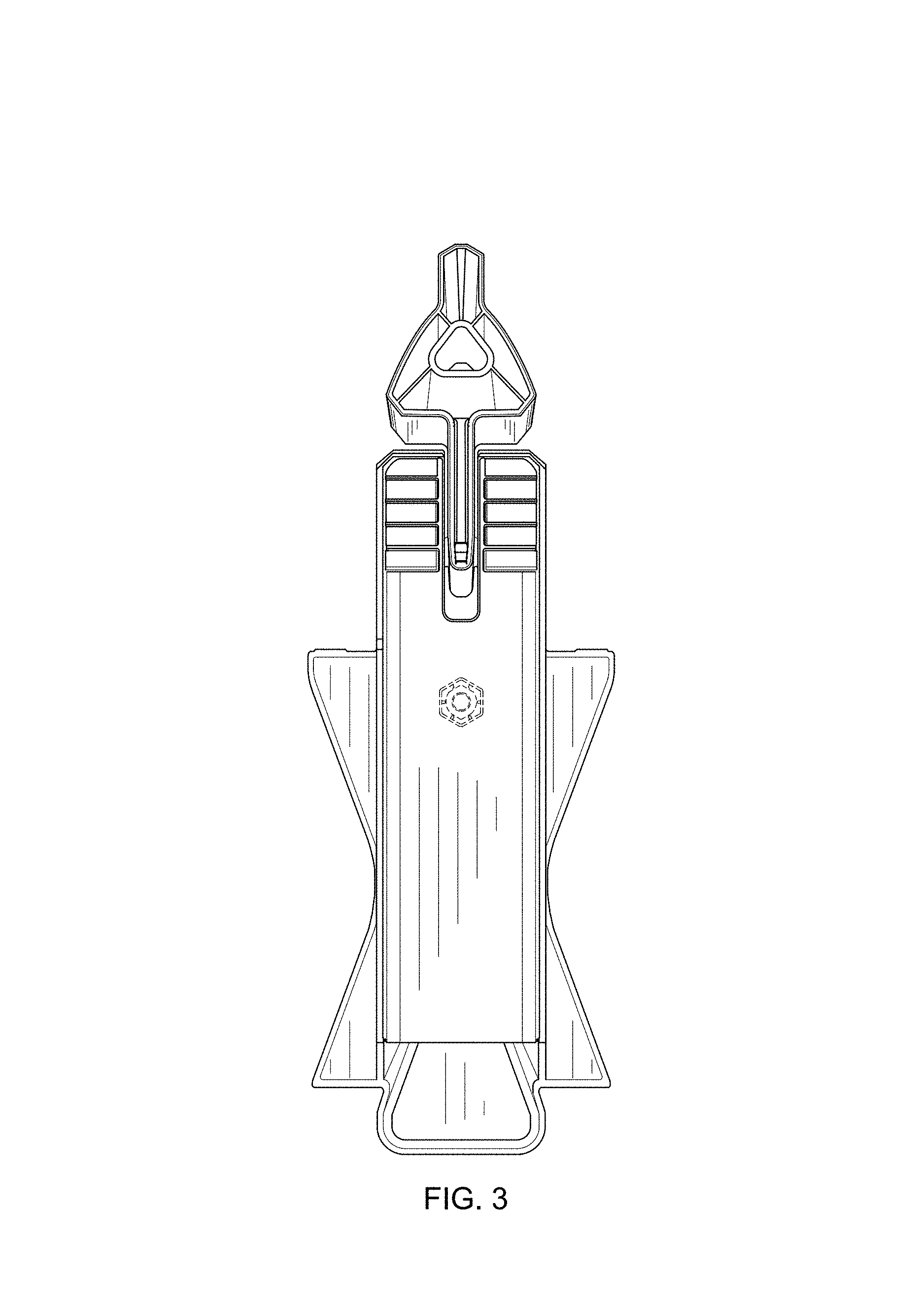
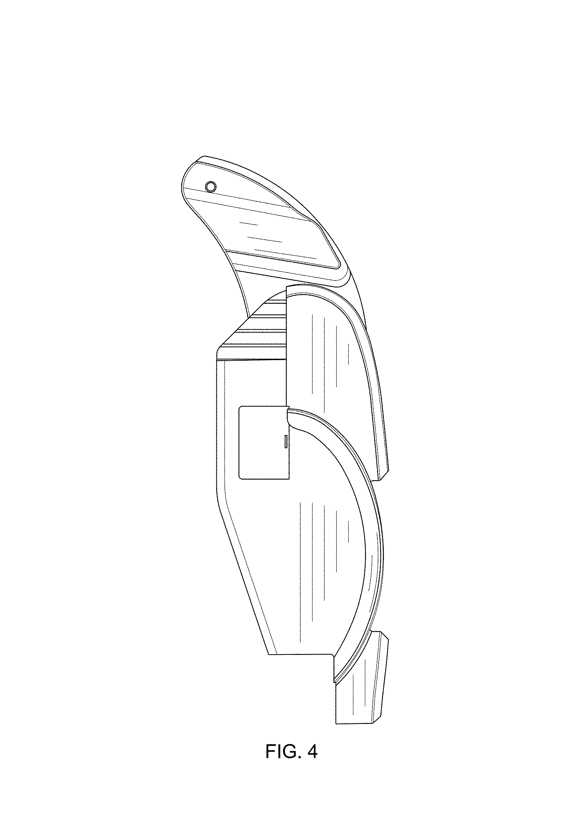
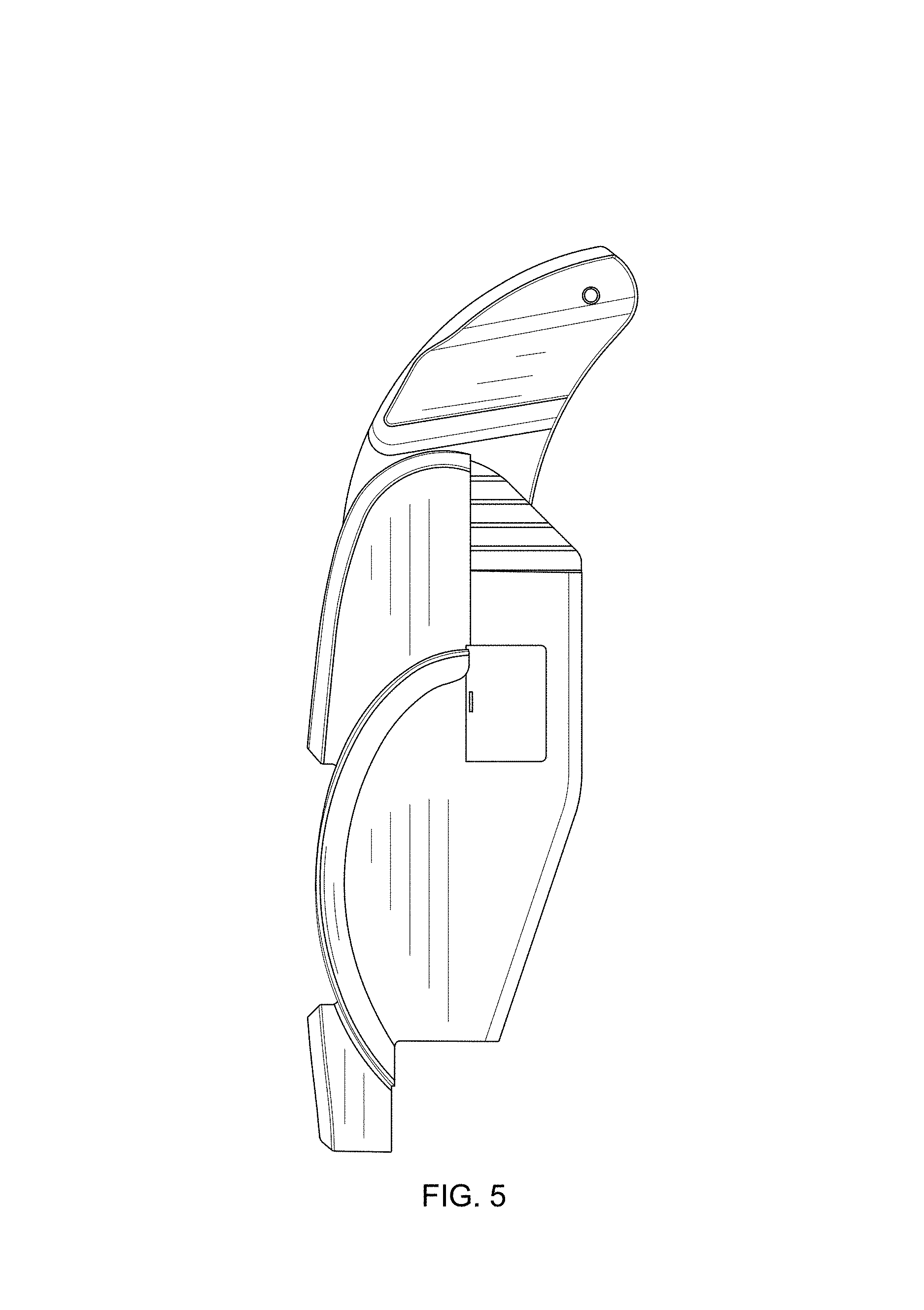
CLAIM The ornamental design for a trampoline tensioner, as shown and described.
| Inventors: | Seaman; Robert Brian (Silverwater, AU), Jones; David Andrew (Silverwater, AU), Hunter; Murray David Kirby (Silverwater, AU), Blattmann; Lee David (Silverwater, AU) | ||||||||||
|---|---|---|---|---|---|---|---|---|---|---|---|
| Applicant: |
|
||||||||||
| Assignee: | Action Sports Equipment Pty
Ltd. (Silverwater, AU) |
||||||||||
| Appl. No.: | D/606,708 | ||||||||||
| Filed: | June 7, 2017 |
Foreign Application Priority Data
| Dec 9, 2016 [AU] | 201616954 | |||
| Current U.S. Class: | D21/797 |
| Current International Class: | 2101 |
| Field of Search: | ;D21/797 ;D8/44,331,394 ;D17/22 |
References Cited [Referenced By]
U.S. Patent Documents
| 3356366 | December 1967 | Barthel |
| 3711092 | January 1973 | Hogue |
| 4976022 | December 1990 | Thornton |
| 5477599 | December 1995 | Blanchard |
| 5664784 | September 1997 | Redlich |
| 7758471 | July 2010 | Nelson |
| D622568 | August 2010 | Sanchez |
| 8038580 | October 2011 | Pieper Genannt Schmauck |
| 8303469 | November 2012 | Alexander |
| D765905 | September 2016 | Oldani |
| D779306 | February 2017 | Finkelstein |
| 2016/0107016 | April 2016 | Haggerty |
| 2016/0166869 | June 2016 | Choi |
| 322533 | Dec 2008 | AU | |||
| 2821111 | Jul 2013 | EP | |||
| WO2015100466 | Jul 2015 | WO | |||
Attorney, Agent or Firm: Young; James L. Westman, Champlin & Koehler, P.A.
Description
FIG. 1 is a perspective view of a trampoline tensioner;
FIG. 2 is a front elevational view of the trampoline tensioner of FIG. 1;
FIG. 3 is a rear elevational view of the trampoline tensioner of FIG. 1;
FIG. 4 is a left side elevational view of the trampoline tensioner of FIG. 1;
FIG. 5 is a right side elevational view of the trampoline tensioner of FIG. 1;
FIG. 6 is a rear elevational view of the trampoline tensioner of FIG. 1, shown in a mounted position relative to its environment;
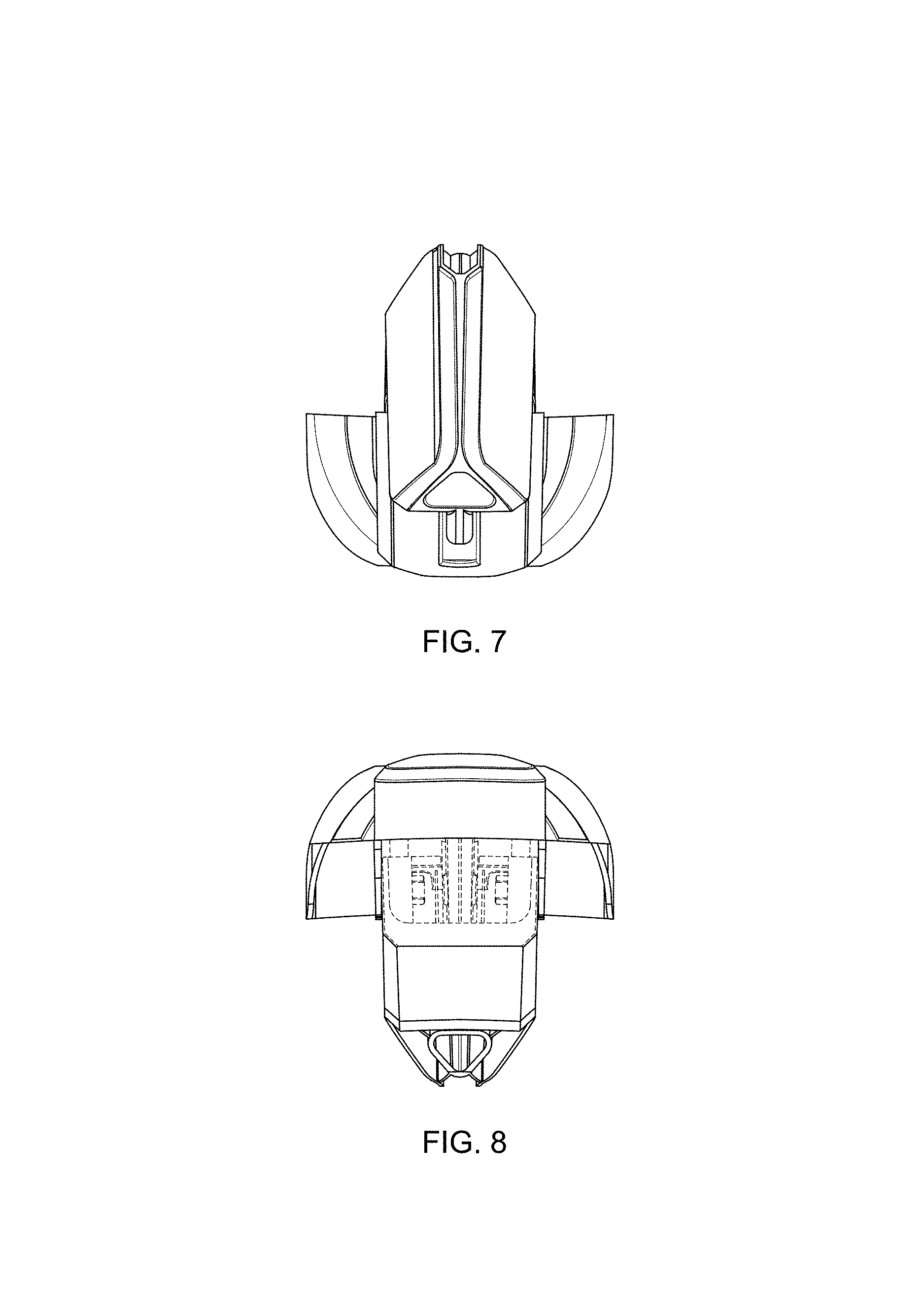
FIG. 7 is a top view of the trampoline tensioner of FIG. 1;
FIG. 8 is a bottom view of the trampoline tensioner of FIG. 1; and,
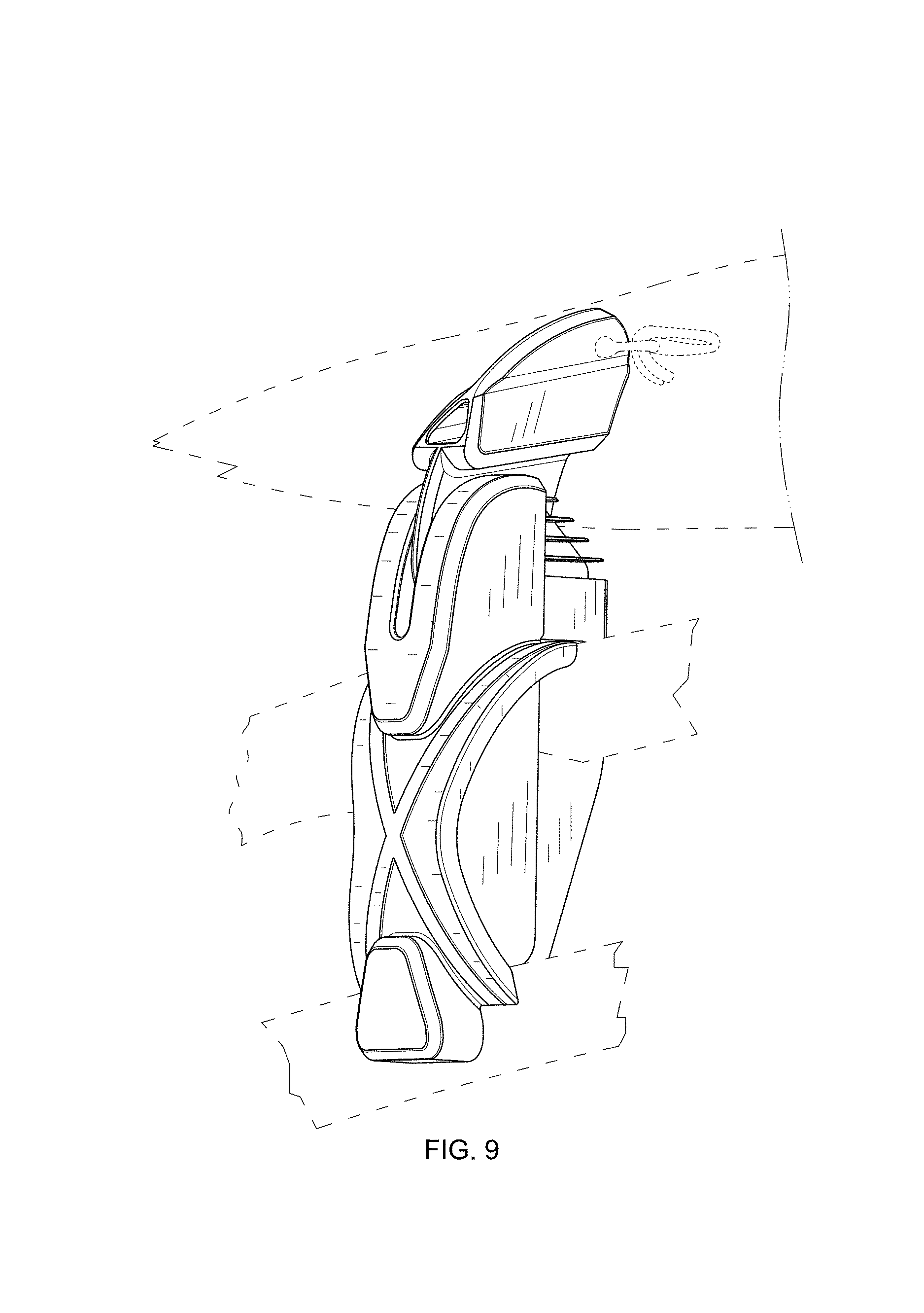
FIG. 9 is a perspective view of the trampoline tensioner of FIG. 1, shown in a mounted position relative to its environment.
The broken lines shown in the FIGS. are for illustrative purposes only and form no part of the claimed design.
* * * * *
D00000
D00001
D00002
D00003
D00004
D00005
D00006
D00007
D00008
XML
uspto.report is an independent third-party trademark research tool that is not affiliated, endorsed, or sponsored by the United States Patent and Trademark Office (USPTO) or any other governmental organization. The information provided by uspto.report is based on publicly available data at the time of writing and is intended for informational purposes only.
While we strive to provide accurate and up-to-date information, we do not guarantee the accuracy, completeness, reliability, or suitability of the information displayed on this site. The use of this site is at your own risk. Any reliance you place on such information is therefore strictly at your own risk.
All official trademark data, including owner information, should be verified by visiting the official USPTO website at www.uspto.gov. This site is not intended to replace professional legal advice and should not be used as a substitute for consulting with a legal professional who is knowledgeable about trademark law.