Coordinate input instrument
Nishizawa
U.S. patent number D851,087 [Application Number D/638,672] was granted by the patent office on 2019-06-11 for coordinate input instrument. This patent grant is currently assigned to Wacom Co., Ltd.. The grantee listed for this patent is Wacom Co., Ltd.. Invention is credited to Naoya Nishizawa.


| United States Patent | D851,087 |
| Nishizawa | June 11, 2019 |
Coordinate input instrument
Claims
CLAIM The ornamental design for a coordinate input instrument, as shown and described.
| Inventors: | Nishizawa; Naoya (Setagaya-ku, JP) | ||||||||||
|---|---|---|---|---|---|---|---|---|---|---|---|
| Applicant: |
|
||||||||||
| Assignee: | Wacom Co., Ltd. (Kazo-shi,
JP) |
||||||||||
| Appl. No.: | D/638,672 | ||||||||||
| Filed: | February 28, 2018 |
Foreign Application Priority Data
| Aug 29, 2017 [JP] | 2017-018472 | |||
| Current U.S. Class: | D14/411 |
| Current International Class: | 1402 |
| Field of Search: | ;D14/411,432 ;351/158,153,144 ;345/7-9,905 ;455/344 ;348/115,53,121,739 |
References Cited [Referenced By]
U.S. Patent Documents
| D712410 | September 2014 | Shu |
| D771630 | November 2016 | Akana et al. |
| D786253 | May 2017 | Akana et al. |
| D826940 | August 2018 | Nishizawa |
| D832840 | November 2018 | Shi |
| D1563169 | Nov 2016 | JP | |||
Attorney, Agent or Firm: Christensen O'Connor Johnson Kindness PLLC
Description
FIG. 1 is a top-front-right perspective view of a representative embodiment of a coordinate input instrument according to my new design;
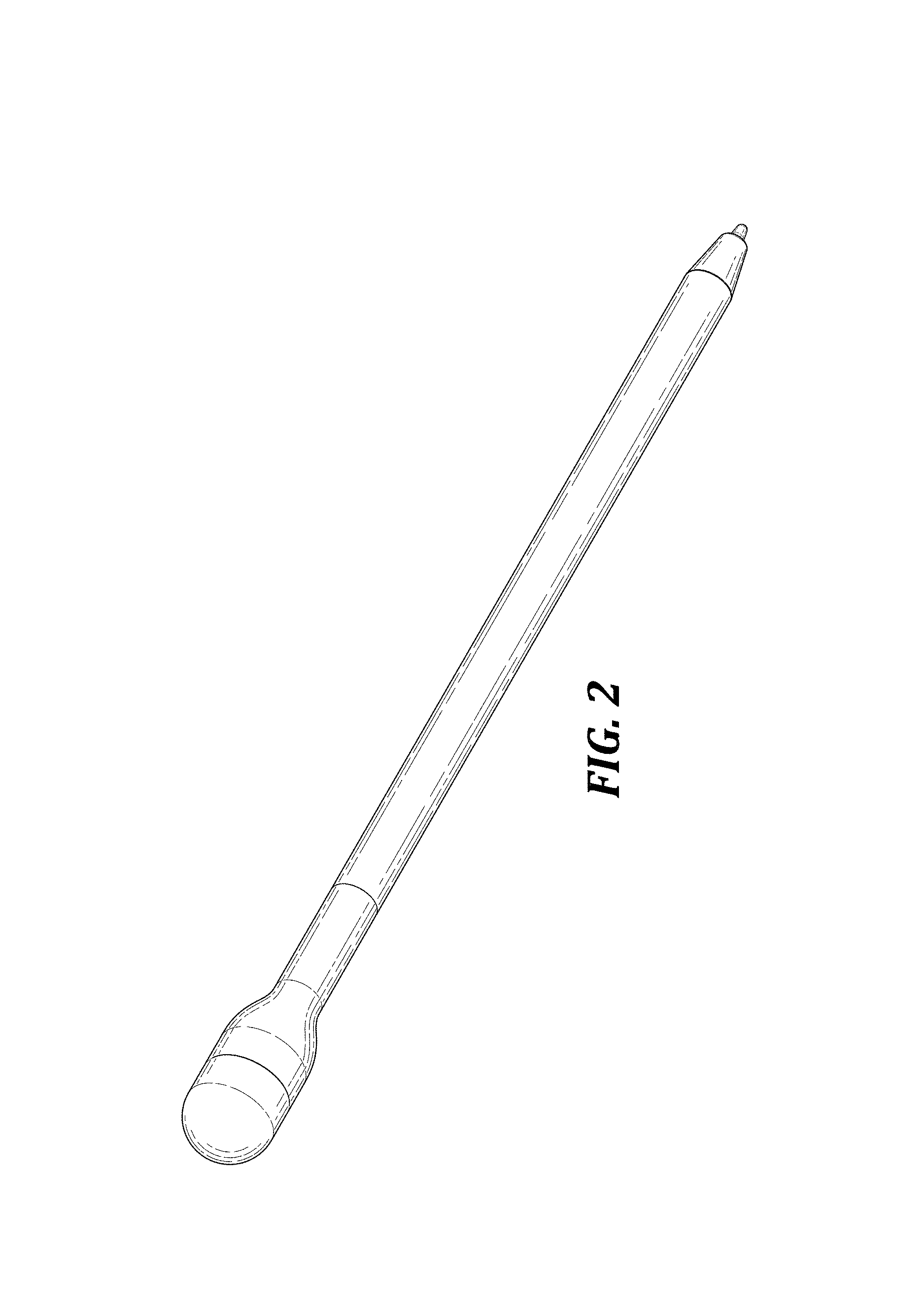
FIG. 2 is a bottom-rear-left perspective view thereof;
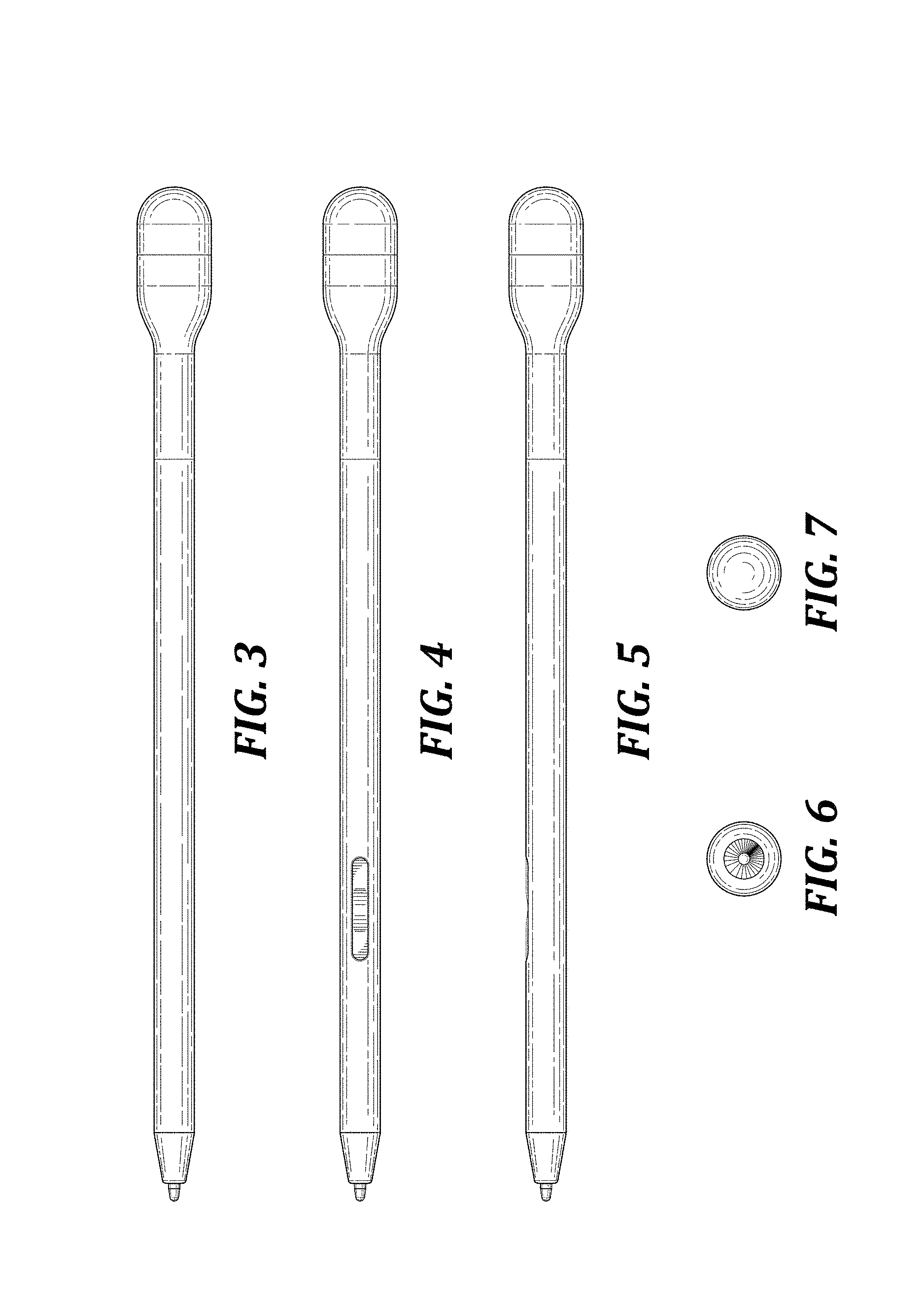
FIG. 3 is a bottom plan view thereof;
FIG. 4 is a top plan view thereof;
FIG. 5 is a right side elevational view thereof, wherein the left side elevational view is a mirror image of the right side elevational view;
FIG. 6 is a front elevational view thereof;
FIG. 7 is a rear elevational view thereof;
FIG. 8 is a partial top-front-right perspective view thereof, as indicated in by the view indicator shown in FIG. 1;
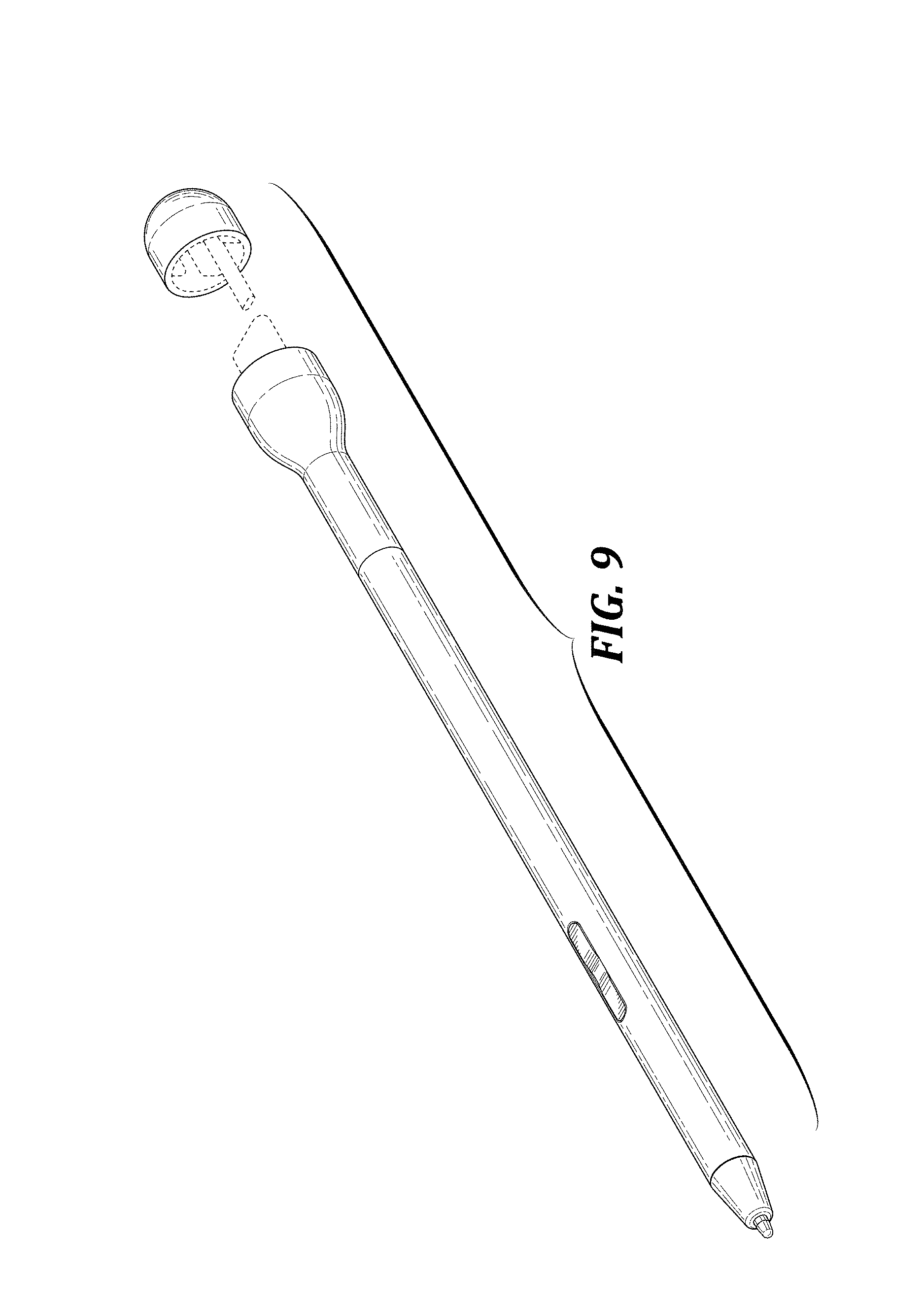
FIG. 9 is a top-front-right perspective view thereof, with a cap removed;
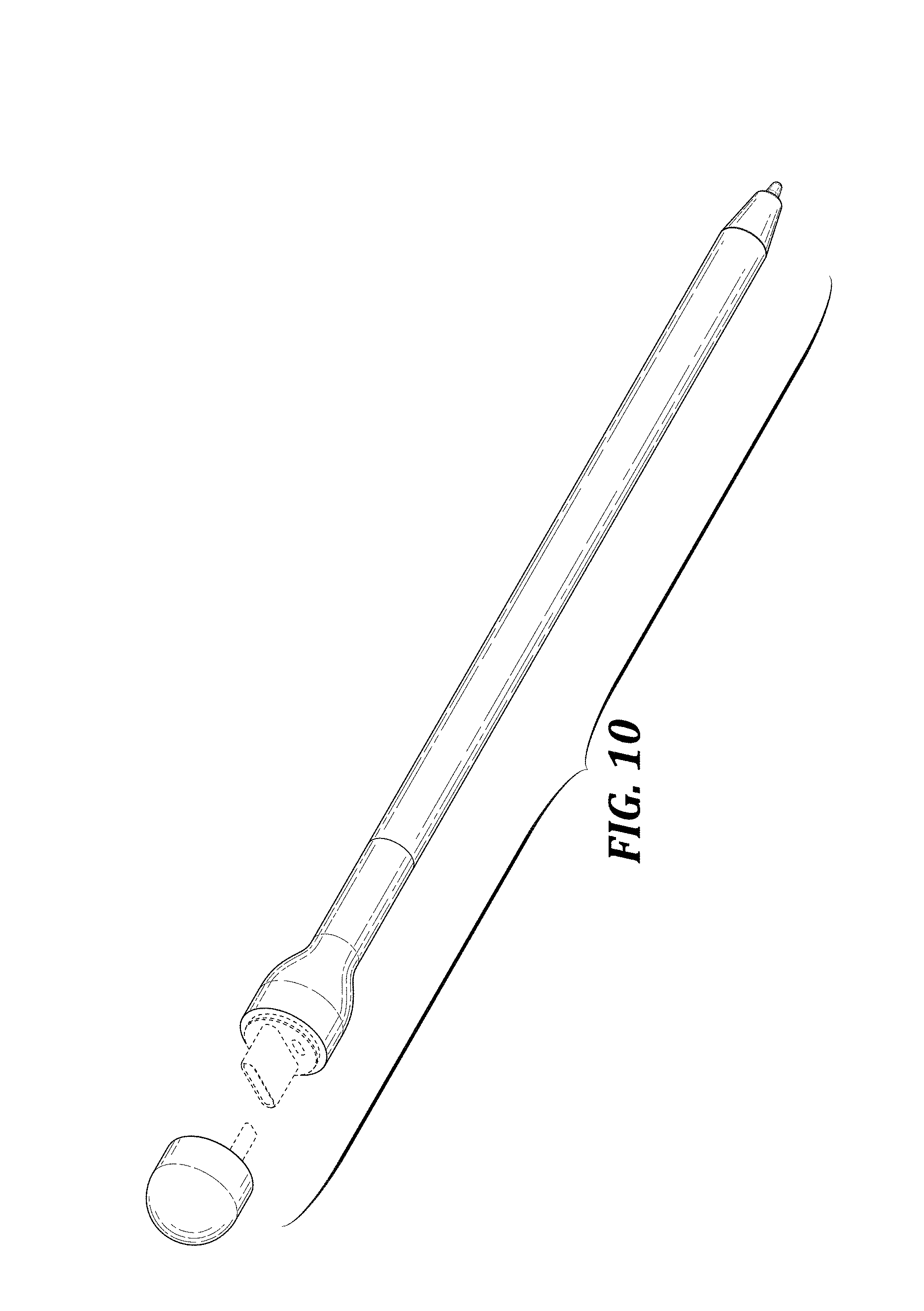
FIG. 10 is a bottom-rear-left perspective view thereof;
FIG. 11 is a bottom plan view thereof;
FIG. 12 is a top plan view thereof;
FIG. 13 is a right side elevational view thereof, wherein the left side elevational view is a mirror image of the right side elevational view;
FIG. 14 is a front elevational view thereof; and,
FIG. 15 is a view indicated by the view indicators shown in FIG. 13.
The dashed broken lines in the drawings show portions of the coordinate input instrument that form no part of the claimed design. The dot-dot-dash broken lines in the drawings indicate from where the enlarged views are taken and form no part of the claimed design.
* * * * *
D00000
D00001
D00002
D00003
D00004
D00005
D00006
D00007
XML
uspto.report is an independent third-party trademark research tool that is not affiliated, endorsed, or sponsored by the United States Patent and Trademark Office (USPTO) or any other governmental organization. The information provided by uspto.report is based on publicly available data at the time of writing and is intended for informational purposes only.
While we strive to provide accurate and up-to-date information, we do not guarantee the accuracy, completeness, reliability, or suitability of the information displayed on this site. The use of this site is at your own risk. Any reliance you place on such information is therefore strictly at your own risk.
All official trademark data, including owner information, should be verified by visiting the official USPTO website at www.uspto.gov. This site is not intended to replace professional legal advice and should not be used as a substitute for consulting with a legal professional who is knowledgeable about trademark law.