Gas cooktop with vertically mounted control knob panel
Pionek , et al.
U.S. patent number D849,478 [Application Number D/554,267] was granted by the patent office on 2019-05-28 for gas cooktop with vertically mounted control knob panel. This patent grant is currently assigned to WOLF APPLIANCE, INC.. The grantee listed for this patent is Wolf Appliance, Inc.. Invention is credited to Patrick W. Best, William Cesare Cesaroni, Curtis Leroy Cruver, IV, Mark R. Eckert, Jason C. Pionek, Curt P. Vitcenda.


View All Diagrams
| United States Patent | D849,478 |
| Pionek , et al. | May 28, 2019 |
Gas cooktop with vertically mounted control knob panel
Claims
CLAIM We claim the ornamental design for a gas cooktop with vertically mounted control knob panel, as shown and described.
| Inventors: | Pionek; Jason C. (Madison, WI), Eckert; Mark R. (Verona, WI), Cruver, IV; Curtis Leroy (Elmhurst, IL), Cesaroni; William Cesare (Glenview, IL), Vitcenda; Curt P. (Edgerton, WI), Best; Patrick W. (Mount Horeb, WI) | ||||||||||
|---|---|---|---|---|---|---|---|---|---|---|---|
| Applicant: |
|
||||||||||
| Assignee: | WOLF APPLIANCE, INC.
(Fitchburg, WI) |
||||||||||
| Appl. No.: | D/554,267 | ||||||||||
| Filed: | February 10, 2016 |
| Current U.S. Class: | D7/406 |
| Current International Class: | 0702 |
| Field of Search: | ;D7/387,402-409,393,394,323,331,332-337,339,340,346-349,351,354,358 ;D12/500,501,502,204 |
References Cited [Referenced By]
U.S. Patent Documents
| 2682859 | July 1954 | Jensen et al. |
| 2699141 | January 1955 | Gaguski |
| 2998733 | September 1961 | Thompson |
| D194137 | November 1962 | Jenn |
| D266348 | September 1982 | Piesco |
| D316293 | April 1991 | Ragonot |
| D324807 | March 1992 | Reid et al. |
| D369940 | May 1996 | Wilsdorf |
| 5936613 | August 1999 | Jaeger et al. |
| D419218 | January 2000 | Mullenmeister |
| 6079401 | June 2000 | Alvord et al. |
| D493090 | July 2004 | Chen et al. |
| D498657 | November 2004 | Milrud et al. |
| D509095 | September 2005 | Grutzke |
| D509987 | September 2005 | Vetter |
| D511290 | November 2005 | Coudurier |
| D525517 | July 2006 | Baldwin |
| D534628 | January 2007 | Chisenhall |
| 7171727 | February 2007 | Wylie et al. |
| 7251861 | August 2007 | Suzuki |
| 7259908 | August 2007 | Wagener et al. |
| D568715 | May 2008 | Gustafson et al. |
| 7381128 | June 2008 | Ogawa et al. |
| D578890 | October 2008 | Swanson et al. |
| 7462795 | December 2008 | Montalvo |
| D597632 | August 2009 | Obara et al. |
| D631726 | February 2011 | Sanchez |
| D644912 | September 2011 | Benold |
| D645702 | September 2011 | Baacke |
| D649004 | November 2011 | Sanchez |
| 8430460 | April 2013 | Erro et al. |
| D696068 | December 2013 | Baacke |
| D697359 | January 2014 | Meda |
| D704028 | May 2014 | Meda et al. |
| D724381 | March 2015 | Pionek et al. |
| D724382 | March 2015 | Pionek et al. |
| D724888 | March 2015 | Lee |
| 8979289 | March 2015 | Camli et al. |
| 9146033 | September 2015 | Cadima et al. |
| D741454 | October 2015 | Freier et al. |
| D752385 | March 2016 | Pionek et al. |
| D752386 | March 2016 | Pionek et al. |
| D764028 | August 2016 | Schoenherr et al. |
| D779262 | February 2017 | Kim |
| D781126 | March 2017 | Pionek et al. |
| D806512 | January 2018 | Chow |
| 2014/0047943 | February 2014 | Camli et al. |
| 2017/0227231 | August 2017 | Pionek |
| 2659190 | Sep 2014 | EP | |||
Assistant Examiner: Shiflet; Nicole C
Attorney, Agent or Firm: Bell & Manning, LLC
Description
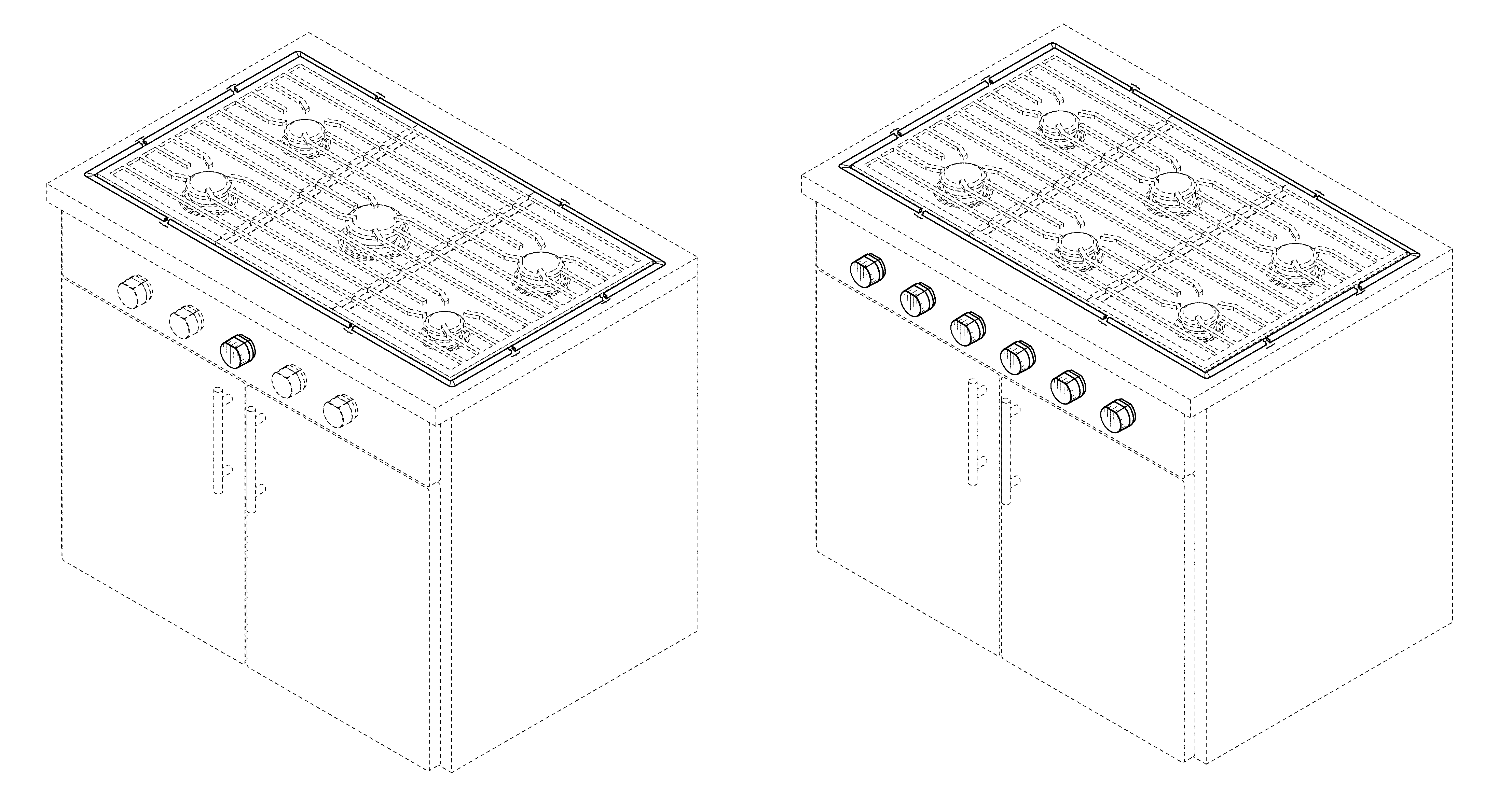
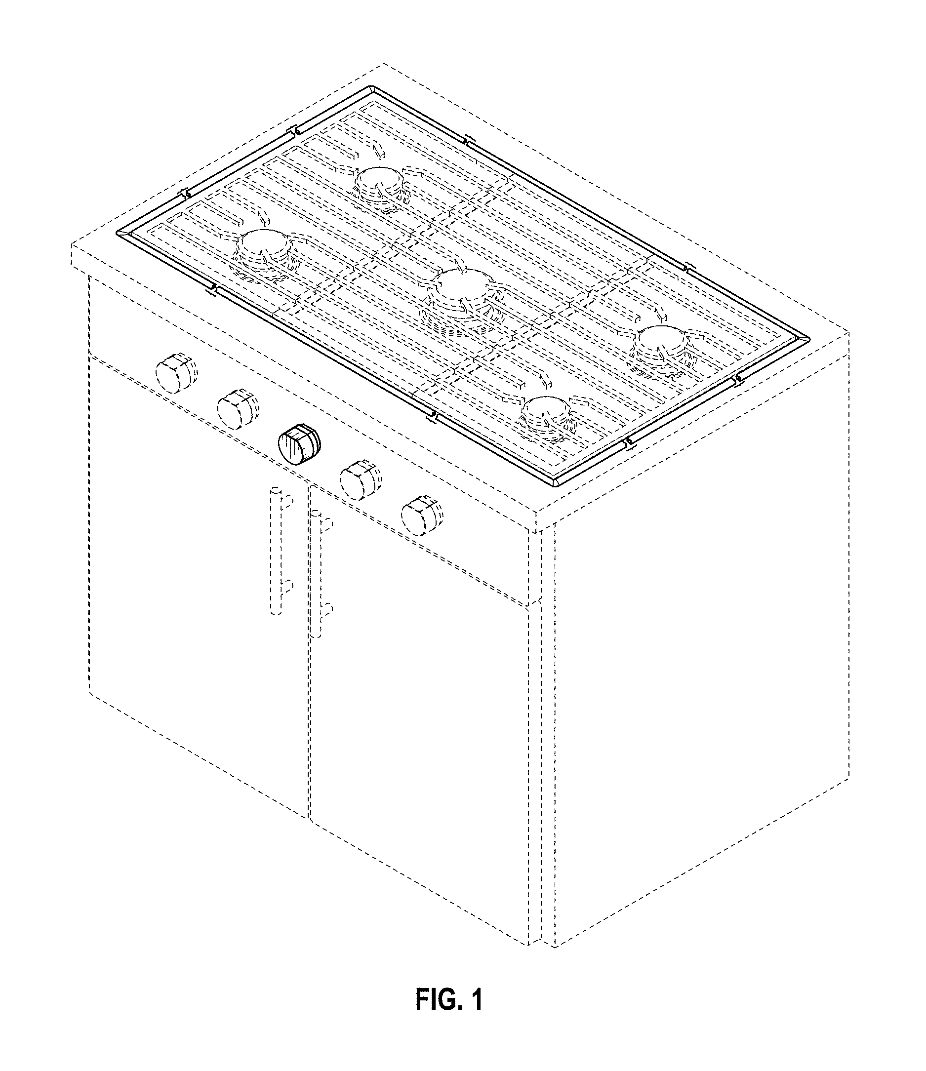
FIG. 1 is a top, front, right perspective view including an environment of use of a first embodiment of a gas cooktop with vertically mounted control knob panel showing our new design;
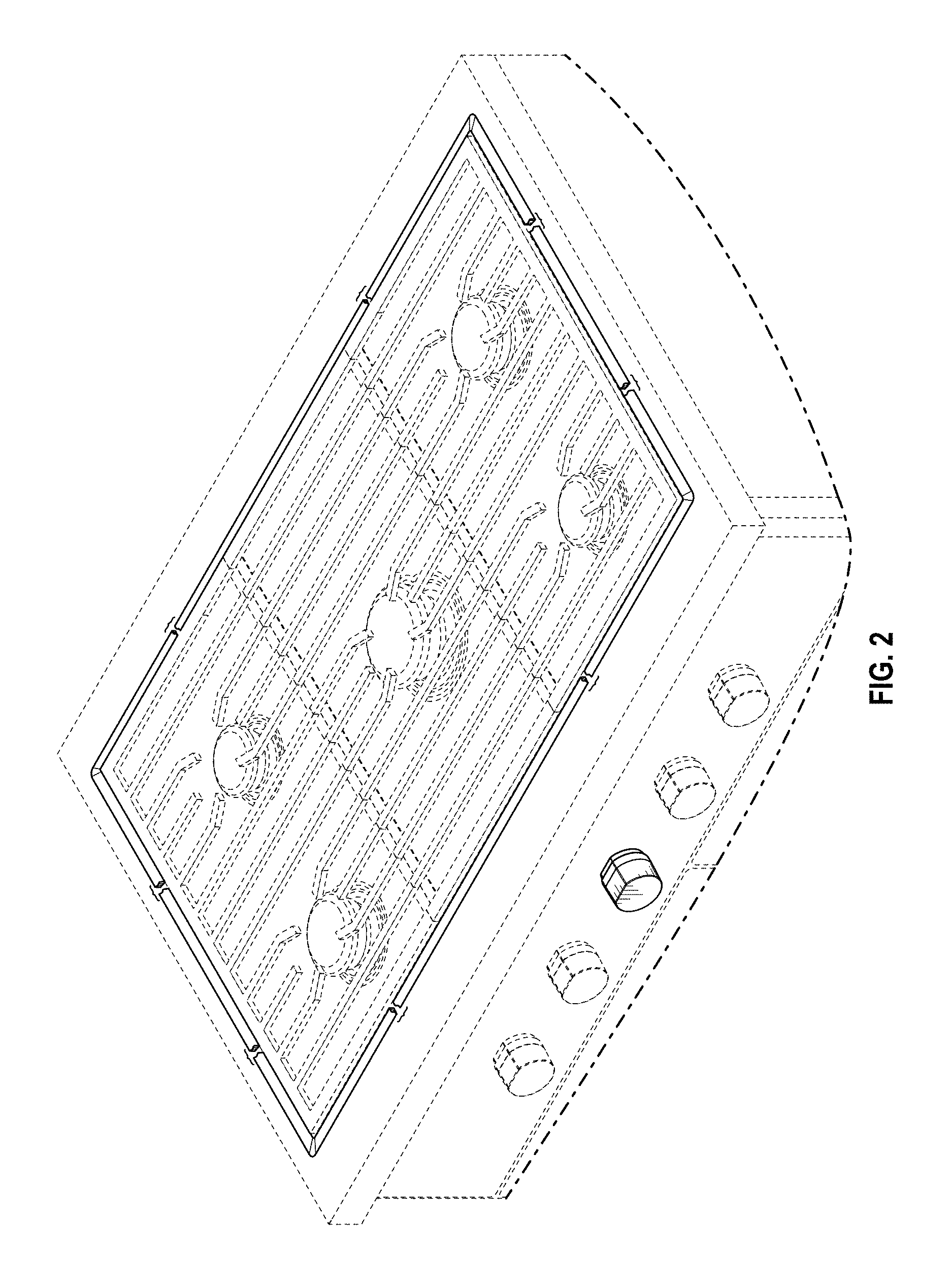
FIG. 2 is a top, front perspective view including an environment of use of the gas cooktop with vertically mounted control knob panel of FIG. 1;
FIG. 3 is a top plan view of the gas cooktop with vertically mounted control knob panel of FIG. 1;
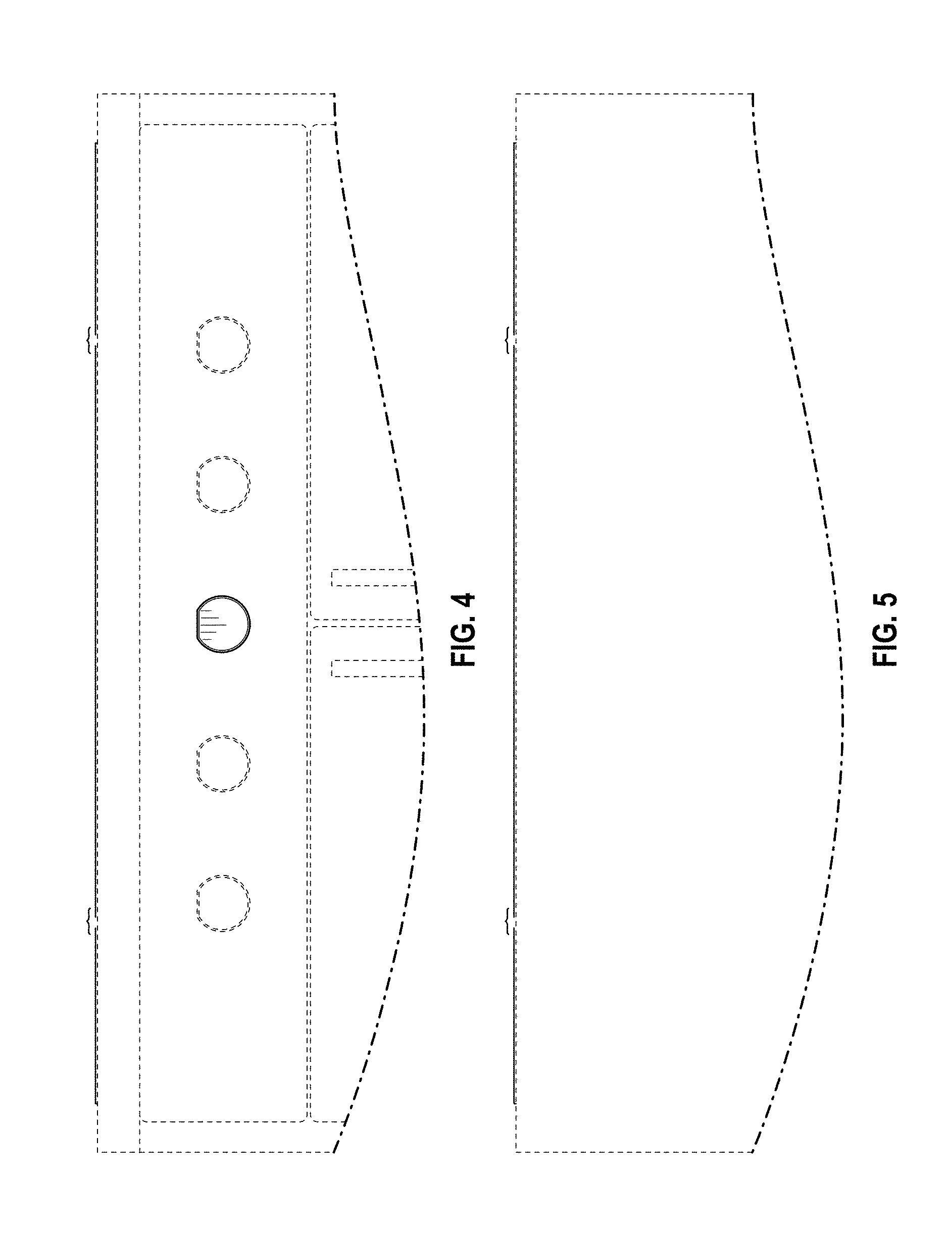
FIG. 4 is a front elevation view of the gas cooktop with vertically mounted control knob panel of FIG. 1;
FIG. 5 is a back elevation view of the gas cooktop with vertically mounted control knob panel of FIG. 1;
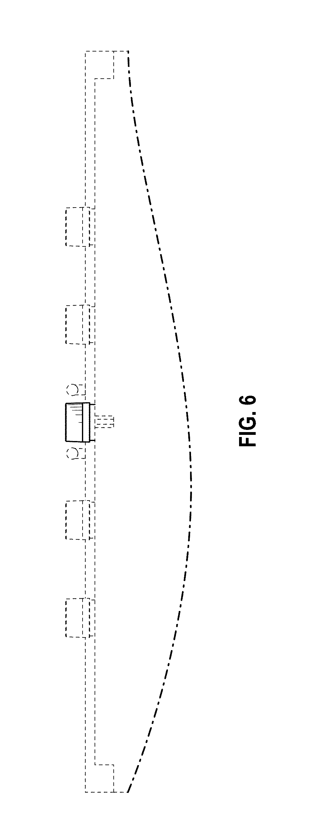
FIG. 6 is a bottom plan view of the gas cooktop with vertically mounted control knob panel of FIG. 1;
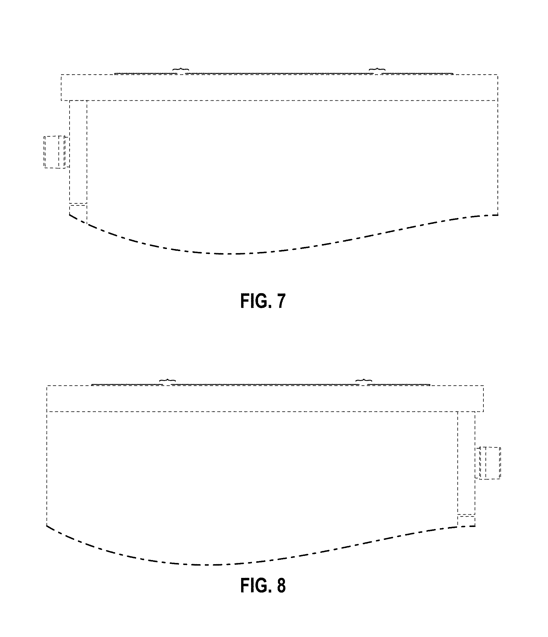
FIG. 7 is a right elevation view of the gas cooktop with vertically mounted control knob panel of FIG. 1;
FIG. 8 is a left elevation view of the gas cooktop with vertically mounted control knob panel of FIG. 1;
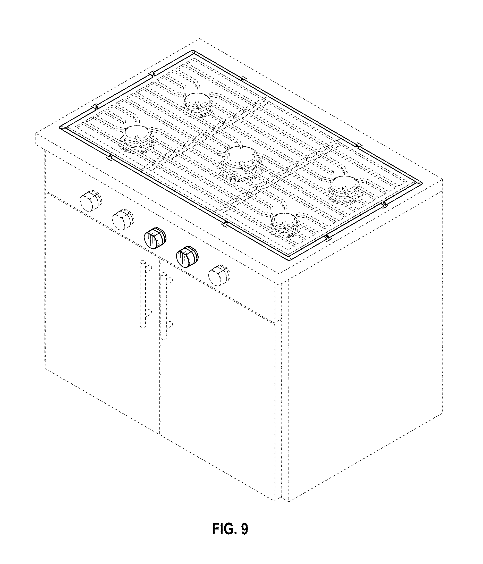
FIG. 9 is a top, front, right perspective view including an environment of use of a second embodiment of the gas cooktop with vertically mounted control knob panel showing our new design;
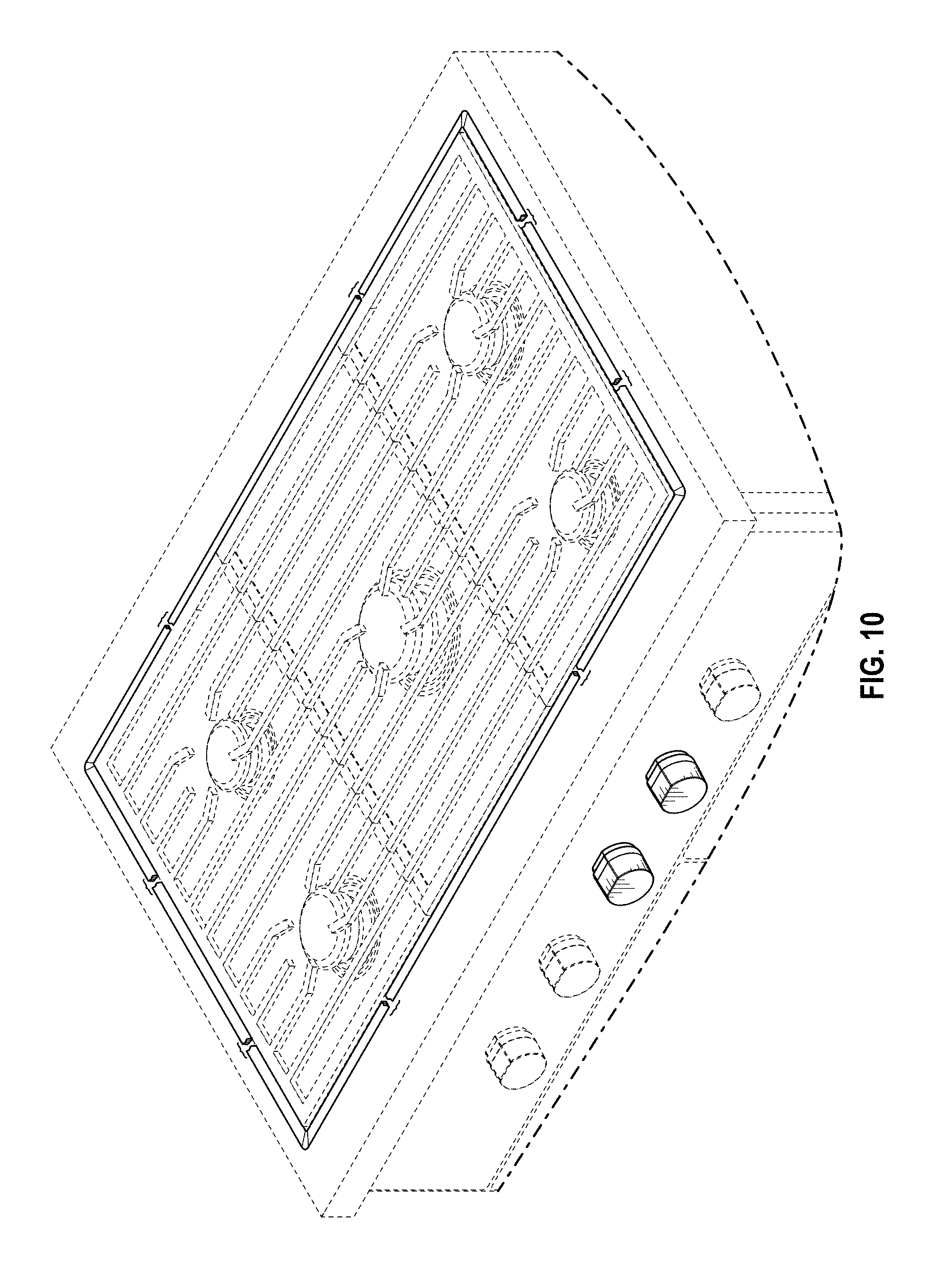
FIG. 10 is a top, front perspective view including an environment of use of the gas cooktop with vertically mounted control knob panel of FIG. 9;
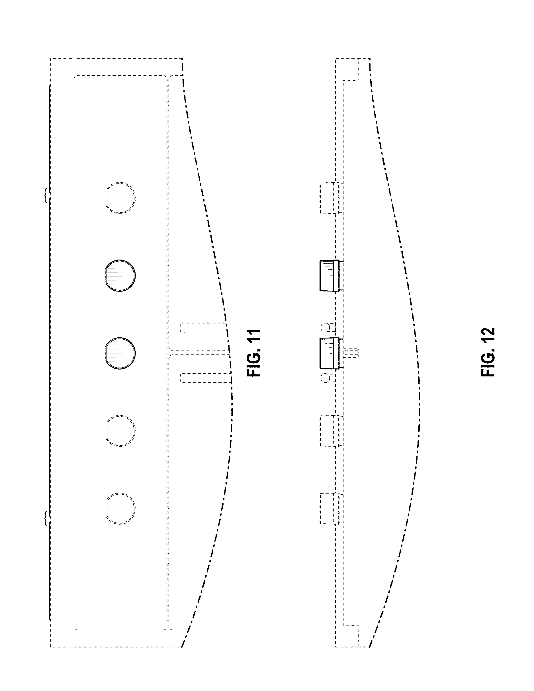
FIG. 11 is a front elevation view of the gas cooktop with vertically mounted control knob panel of FIG. 9;
FIG. 12 is a bottom plan view of the gas cooktop with vertically mounted control knob panel of FIG. 9;
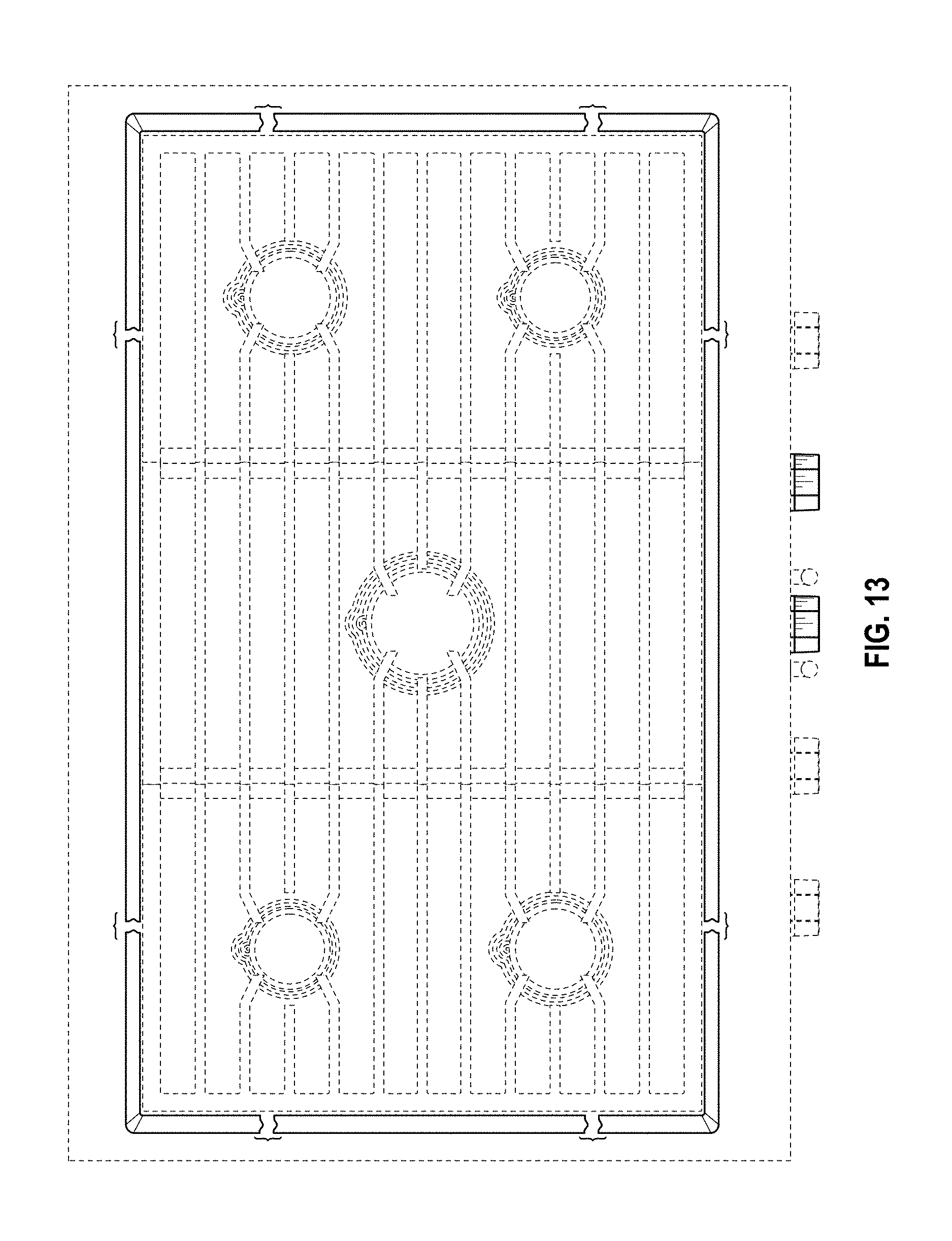
FIG. 13 is a top plan view of the gas cooktop with vertically mounted control knob panel of FIG. 9;
FIG. 14 is a top, front, right perspective view including an environment of use of a third embodiment of the gas cooktop with vertically mounted control knob panel showing our new design;
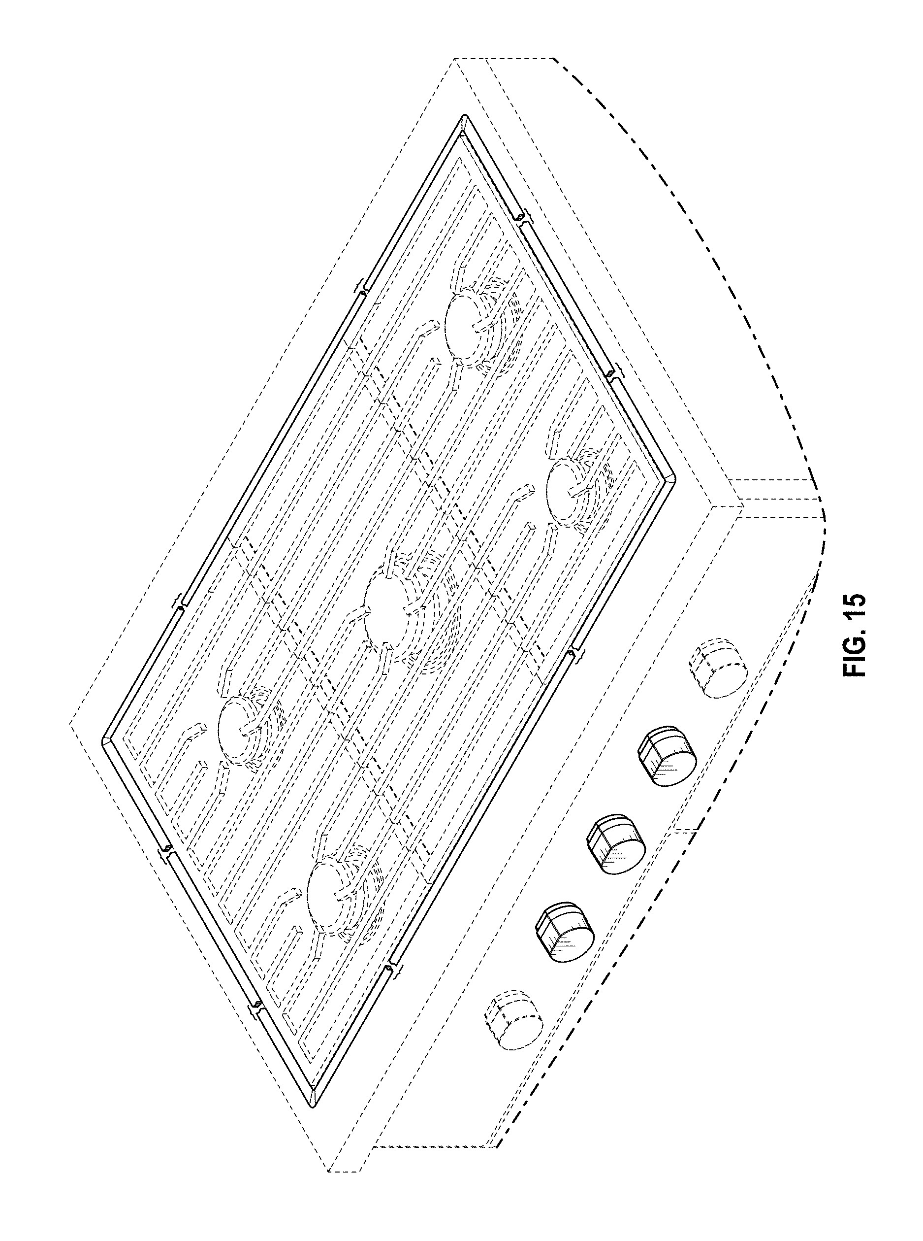
FIG. 15 is a top, front perspective view including an environment of use of the gas cooktop with vertically mounted control knob panel of FIG. 14;
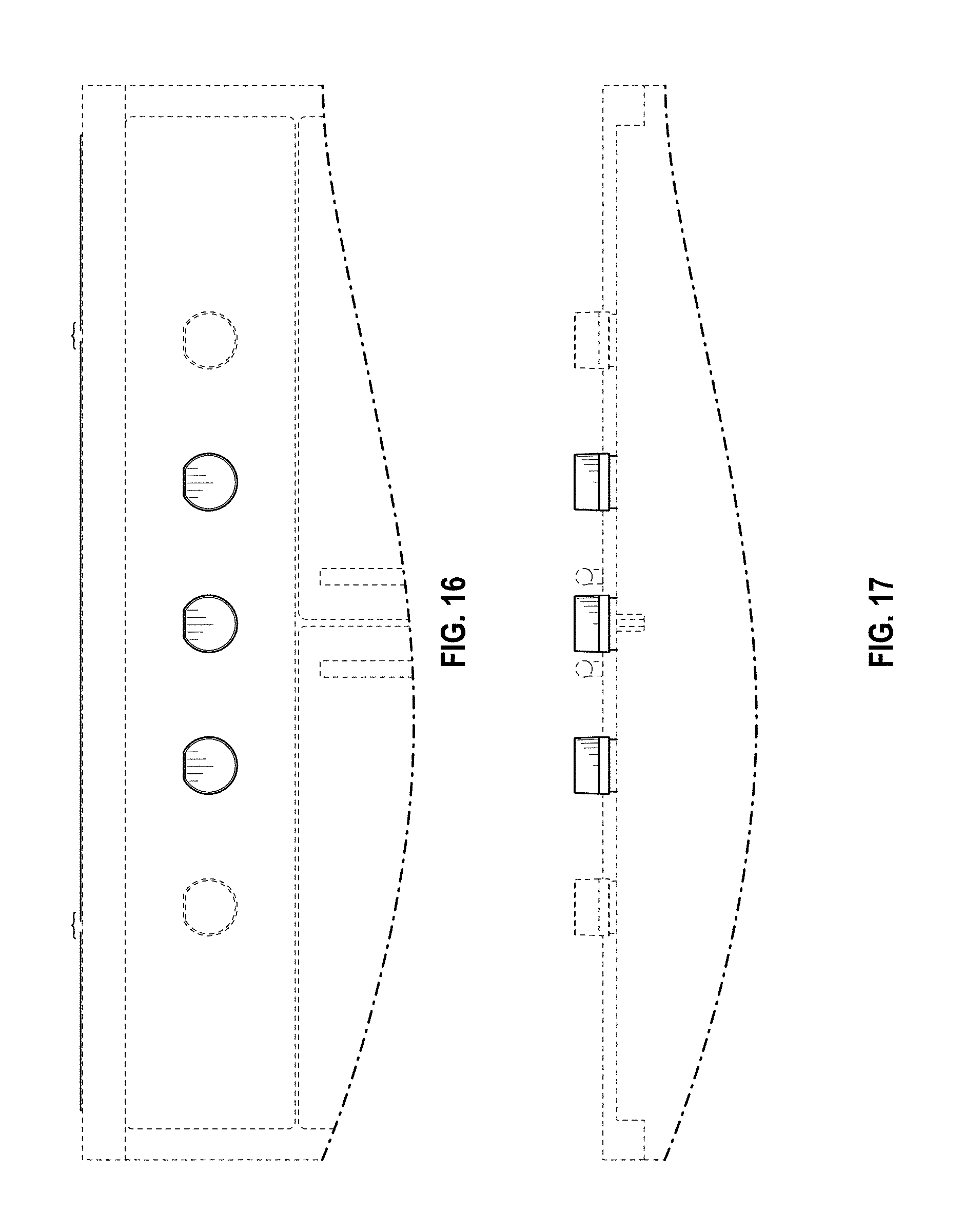
FIG. 16 is a front elevation view of the gas cooktop with vertically mounted control knob panel of FIG. 14;
FIG. 17 is a bottom plan view of the gas cooktop with vertically mounted control knob panel of FIG. 14;
FIG. 18 is a top plan view of the gas cooktop with vertically mounted control knob panel of FIG. 14;
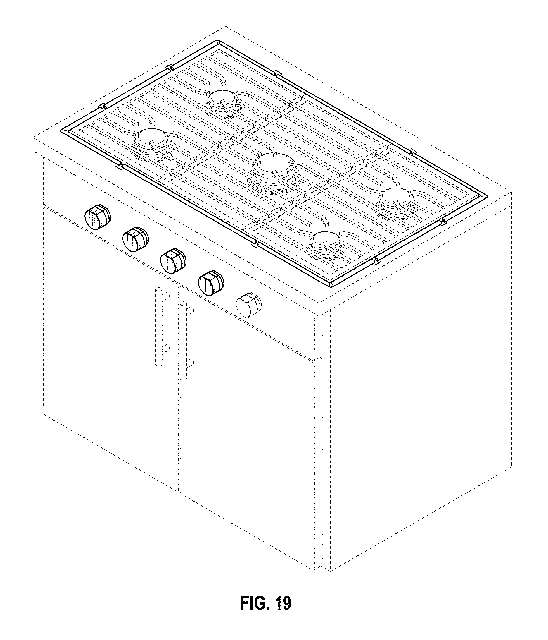
FIG. 19 is a top, front, right perspective view including an environment of use of a fourth embodiment of the gas cooktop with vertically mounted control knob panel showing our new design;
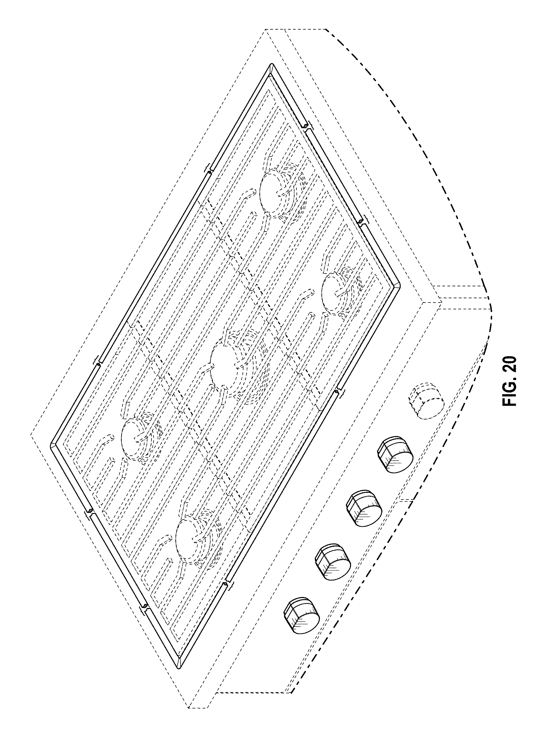
FIG. 20 is a top, front perspective view including an environment of use of the gas cooktop with vertically mounted control knob panel of FIG. 19;
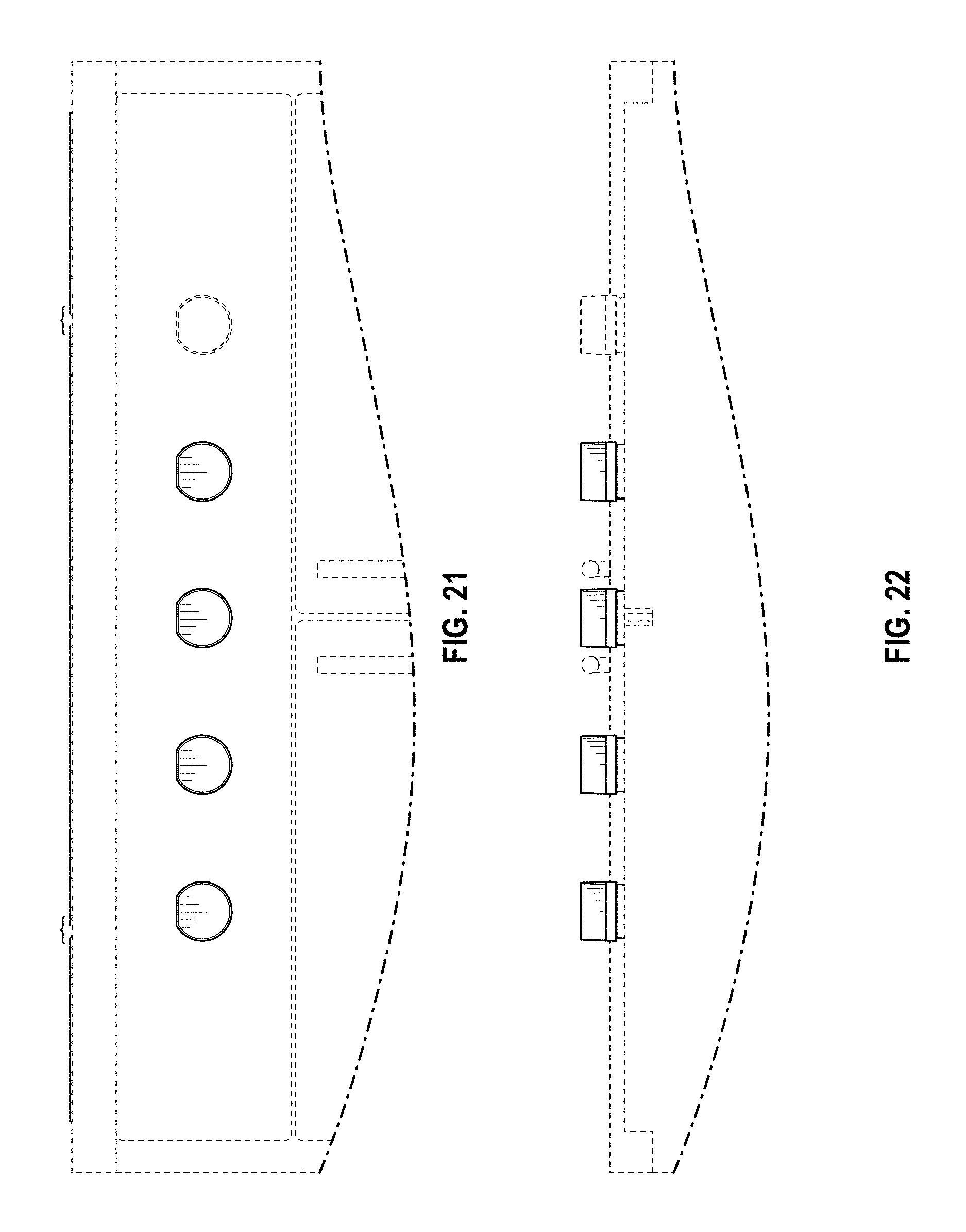
FIG. 21 is a front elevation view of the gas cooktop with vertically mounted control knob panel of FIG. 19;
FIG. 22 is a bottom plan view of the gas cooktop with vertically mounted control knob panel of FIG. 19;
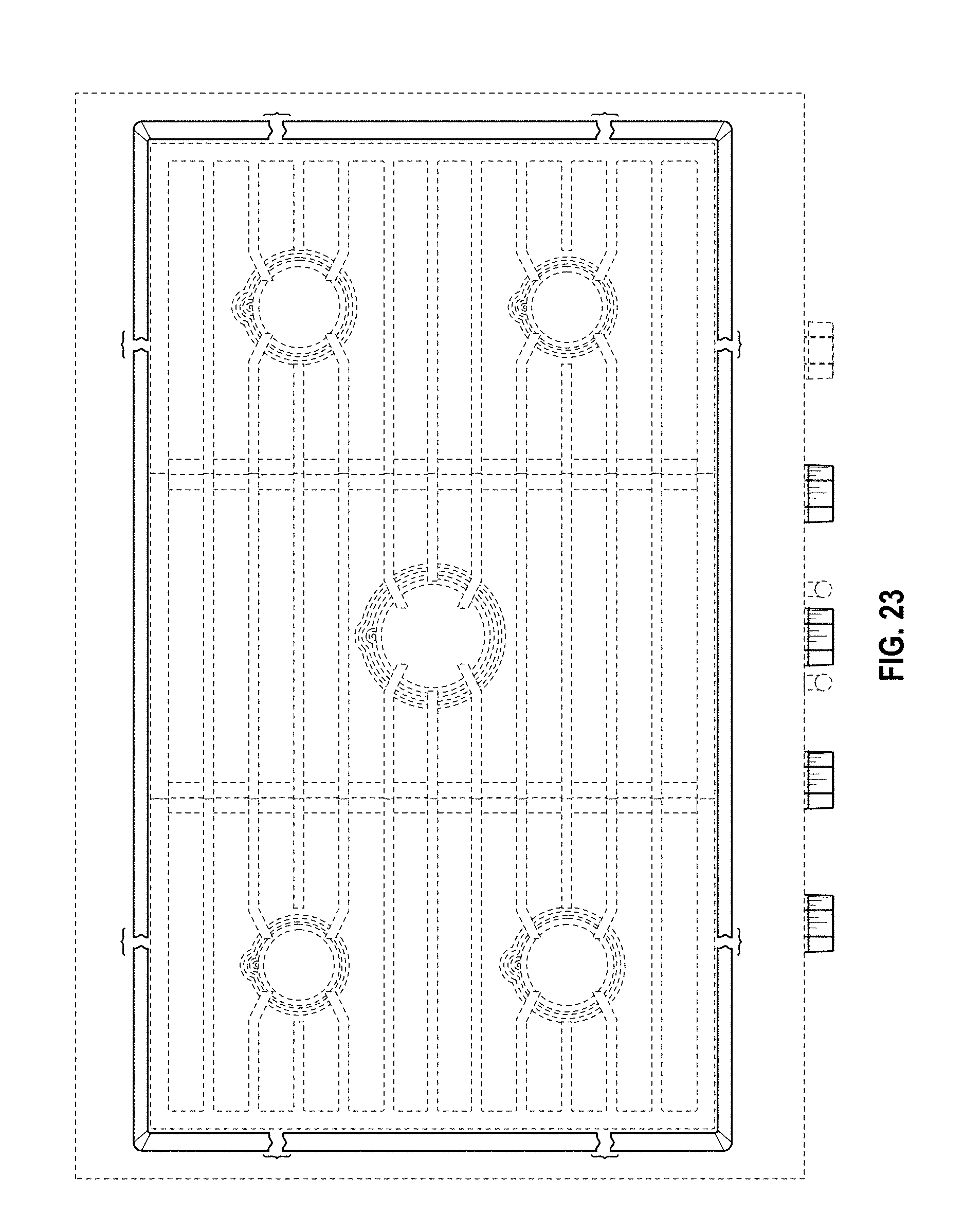
FIG. 23 is a top plan view of the gas cooktop with vertically mounted control knob panel of FIG. 19;
FIG. 24 is a left elevation view of the gas cooktop with vertically mounted control knob panel of FIG. 19;
FIG. 25 is a top, front, right perspective view including an environment of use of a fifth embodiment of the gas cooktop with vertically mounted control knob panel showing our new design;
FIG. 26 is a top, front perspective view including an environment of use of the gas cooktop with vertically mounted control knob panel of FIG. 25;
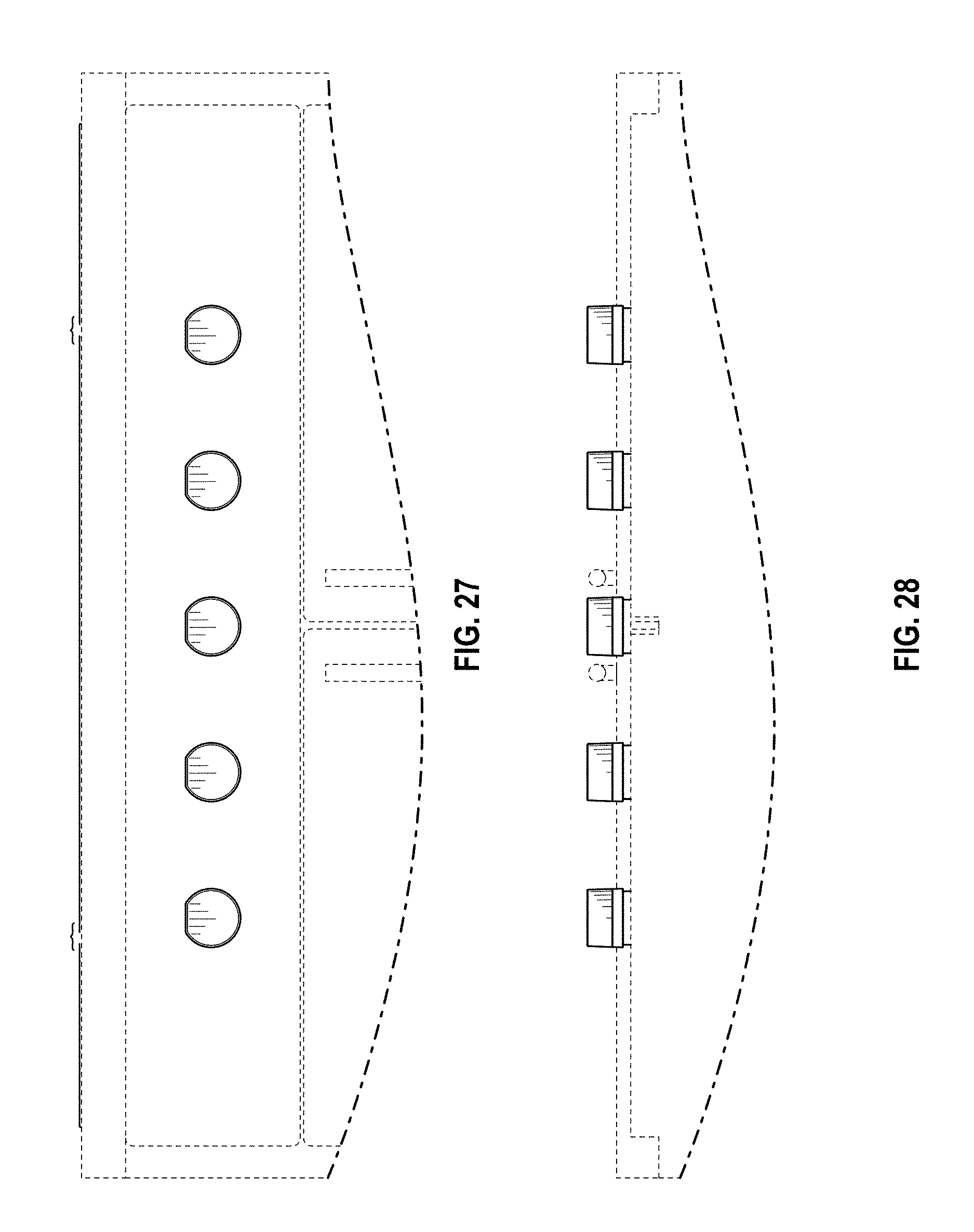
FIG. 27 is a front elevation view of the gas cooktop with vertically mounted control knob panel of FIG. 25;
FIG. 28 is a bottom plan view of the gas cooktop with vertically mounted control knob panel of FIG. 25;
FIG. 29 is a top plan view of the gas cooktop with vertically mounted control knob panel of FIG. 25;
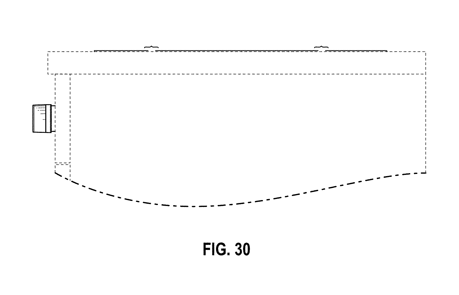
FIG. 30 is a right elevation view of the gas cooktop with vertically mounted control knob panel of FIG. 25;
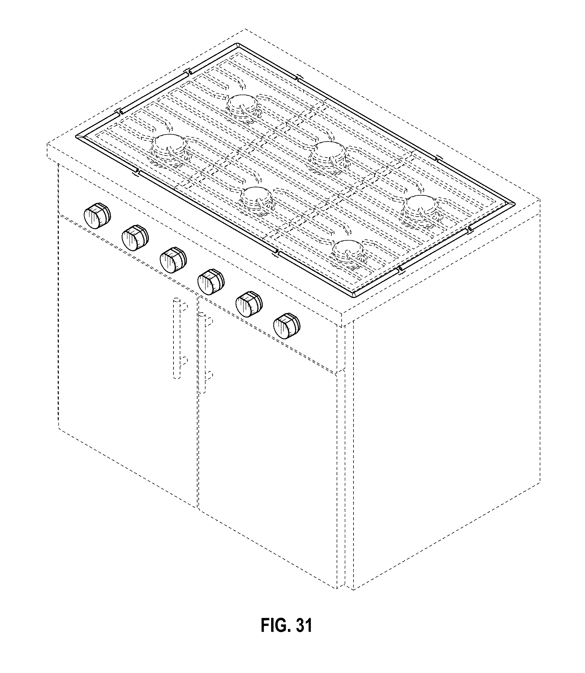
FIG. 31 is a top, front, right perspective view including an environment of use of a sixth embodiment of the gas cooktop with vertically mounted control knob panel showing our new design;
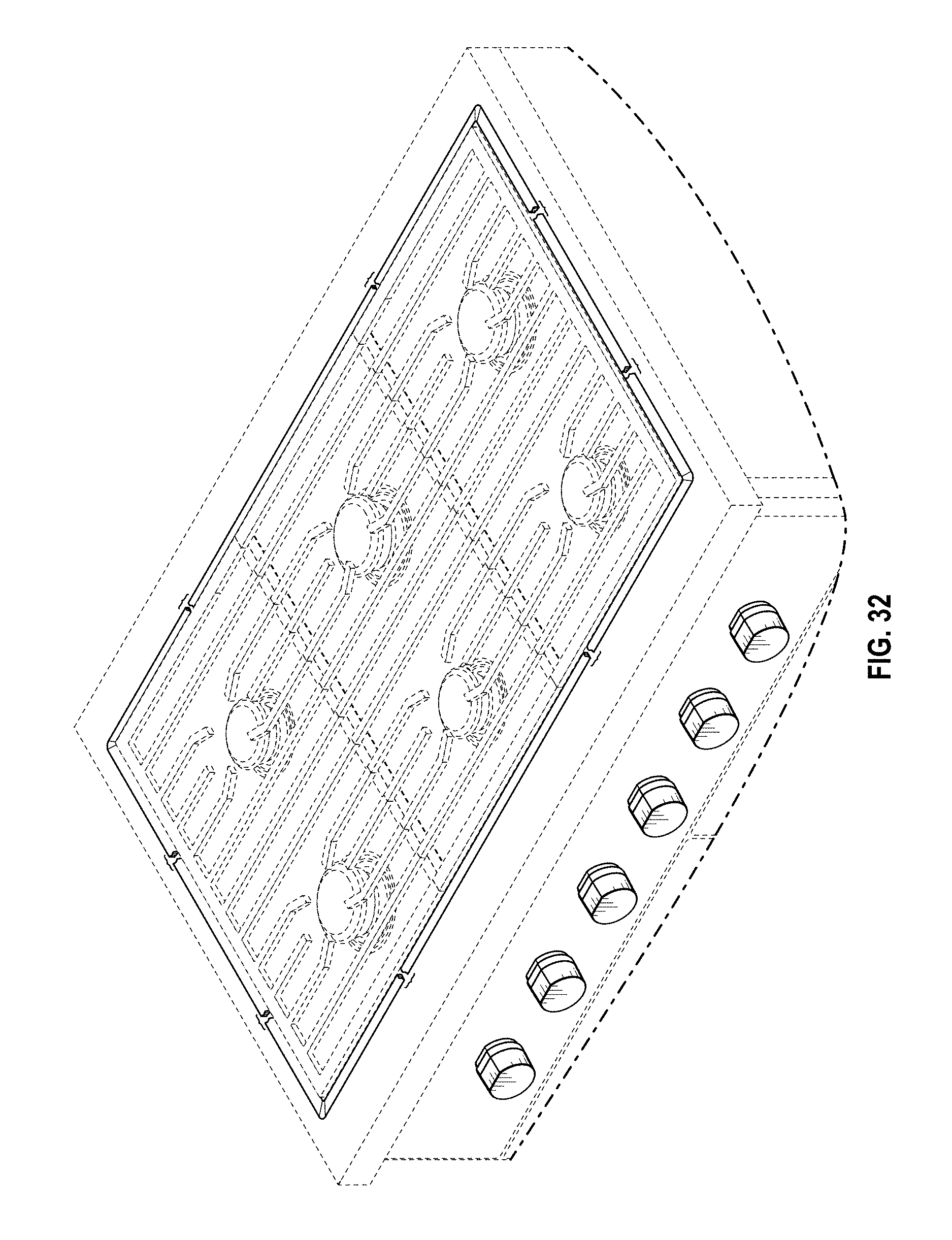
FIG. 32 is a top, front perspective view including an environment of use of the gas cooktop with vertically mounted control knob panel of FIG. 31;
FIG. 33 is a front elevation view of the gas cooktop with vertically mounted control knob panel of FIG. 31;
FIG. 34 is a bottom plan view of the gas cooktop with vertically mounted control knob panel of FIG. 31; and,
FIG. 35 is a top plan view of the gas cooktop with vertically mounted control knob panel of FIG. 31.
The broken lines in FIGS. 1-35 are included for the purpose of illustrating portions of the environment in which the gas cooktop with vertically mounted control knob panel is used. The broken lines in FIGS. 1-35 form no part of the claimed design. The dash-dot lines are included for the purpose of illustrating a boundary below which no additional portion of the environment is shown. The dash-dot lines in FIGS. 2, 4-8, 10-12, 15-17, 20-22, 24, 26-28, 30, and 32-34 form no part of the claimed design. The appearance of any portion of the first, second, third, fourth, fifth, and sixth embodiments of the vertically mounted gas cooktop control knob panel between the break lines spanned by a bracket "{" forms no part of the claimed design of FIGS. 1-35. The back elevation views of the second, third, fourth, fifth, and sixth embodiments are identical to FIG. 5. The right elevation views of the second, third, and fourth embodiments are identical to FIG. 7. The right elevation view of the sixth embodiment is identical to FIG. 30. The left elevation views of the second and third embodiments are identical to FIG. 8. The left elevation views of the fifth and sixth embodiments are identical to FIG. 24.
* * * * *
D00000
D00001
D00002
D00003
D00004
D00005
D00006
D00007
D00008
D00009
D00010
D00011
D00012
D00013
D00014

D00015
D00016
D00017
D00018
D00019

D00020

D00021

D00022
D00023

D00024
D00025
D00026
D00027

D00028

XML
uspto.report is an independent third-party trademark research tool that is not affiliated, endorsed, or sponsored by the United States Patent and Trademark Office (USPTO) or any other governmental organization. The information provided by uspto.report is based on publicly available data at the time of writing and is intended for informational purposes only.
While we strive to provide accurate and up-to-date information, we do not guarantee the accuracy, completeness, reliability, or suitability of the information displayed on this site. The use of this site is at your own risk. Any reliance you place on such information is therefore strictly at your own risk.
All official trademark data, including owner information, should be verified by visiting the official USPTO website at www.uspto.gov. This site is not intended to replace professional legal advice and should not be used as a substitute for consulting with a legal professional who is knowledgeable about trademark law.