Camera
Hogstedt , et al.
U.S. patent number D849,105 [Application Number D/597,277] was granted by the patent office on 2019-05-21 for camera. This patent grant is currently assigned to FLIR SYSTEMS AB. The grantee listed for this patent is FLIR Systems AB. Invention is credited to Niklas Briheim, Anton Hoffman, Christian Hogstedt, Markus Stridsberg.


View All Diagrams
| United States Patent | D849,105 |
| Hogstedt , et al. | May 21, 2019 |
Camera
Claims
CLAIM The ornamental design for a camera, as shown and described.
| Inventors: | Hogstedt; Christian (Nacka, SE), Hoffman; Anton (Bromma, SE), Briheim; Niklas (Stockholm, SE), Stridsberg; Markus (Stockholm, SE) | ||||||||||
|---|---|---|---|---|---|---|---|---|---|---|---|
| Applicant: |
|
||||||||||
| Assignee: | FLIR SYSTEMS AB (Taby,
SE) |
||||||||||
| Appl. No.: | D/597,277 | ||||||||||
| Filed: | March 15, 2017 |
| Current U.S. Class: | D16/218 |
| Current International Class: | 1601 |
| Field of Search: | ;D16/200,202-206,208,217,218,219 ;348/340,373-376 ;396/89,176-178,535,539-541 |
References Cited [Referenced By]
U.S. Patent Documents
| 5032857 | July 1991 | Miki |
| D404413 | January 1999 | Ida |
| D557308 | December 2007 | Matsuda |
| D564560 | March 2008 | Funakoshi |
| D570891 | June 2008 | Miyahara |
| D579475 | October 2008 | Aronsson |
| D598038 | August 2009 | Takahashi |
| 7924312 | April 2011 | Packard |
| D665004 | August 2012 | Lofgren |
| D718801 | December 2014 | Zetterlund |
| D753208 | April 2016 | Elrod |
| D758468 | June 2016 | Darty |
| 2005/0200746 | September 2005 | Ahn |
Other References
|
Flir Systems AB, "Camera Module", U.S. Appl. No. 29/525,225 Apr. 28, 2015, 19 pages. cited by applicant. |
Primary Examiner: Almatrahi; Ramzi S
Attorney, Agent or Firm: Haynes and Boone, LLP
Description
FIG. 1 is a front, left, and top perspective view of a camera showing the new design illustrated in a first orientation;
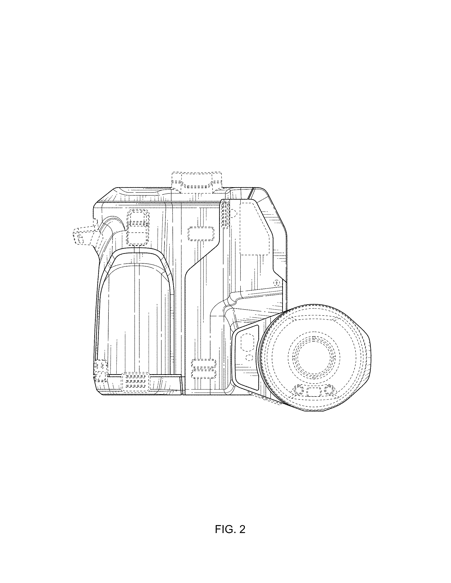
FIG. 2 is a front elevational view thereof;
FIG. 3 is a rear elevational view thereof;
FIG. 4 is a right side view thereof;
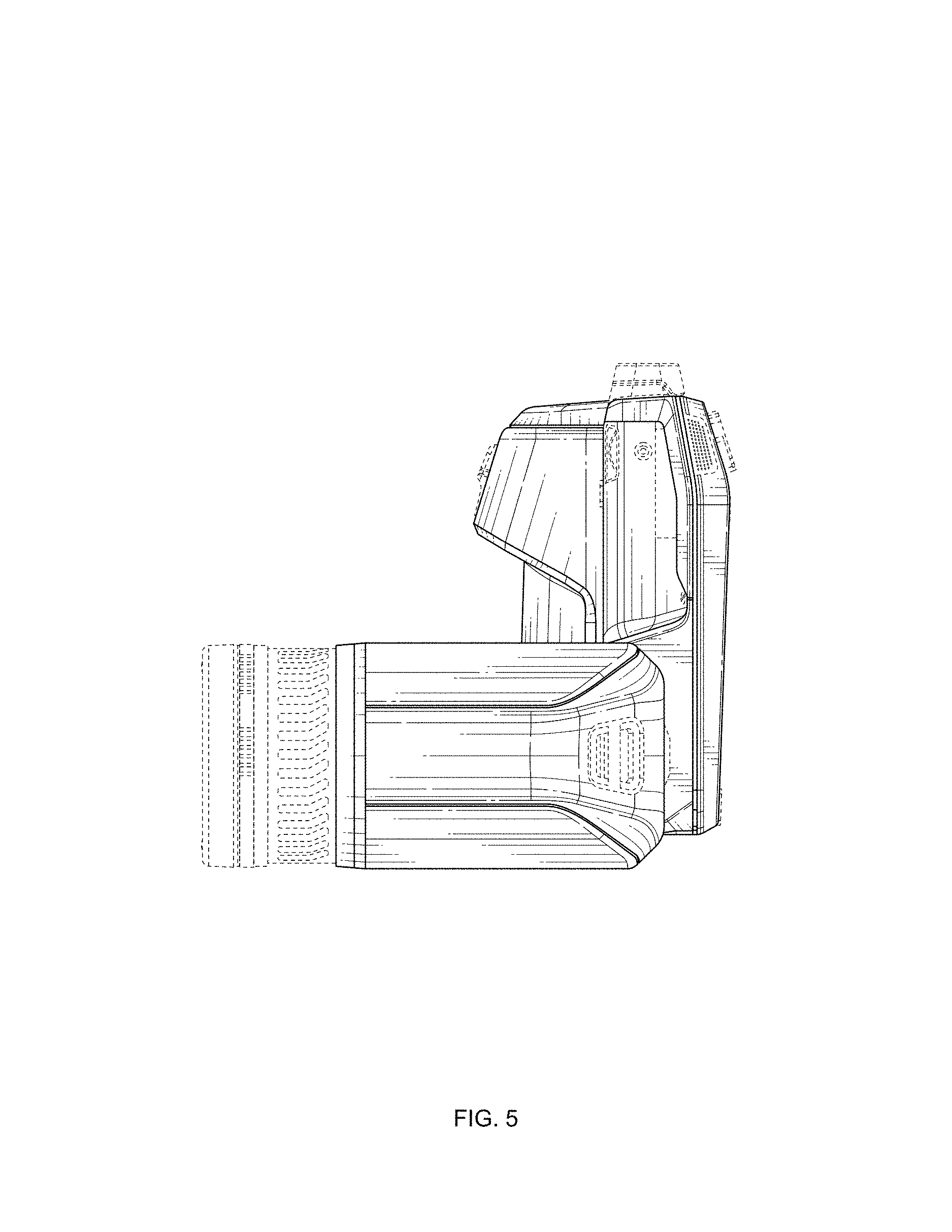
FIG. 5 is a left side view thereof;
FIG. 6 is a top plan view thereof;
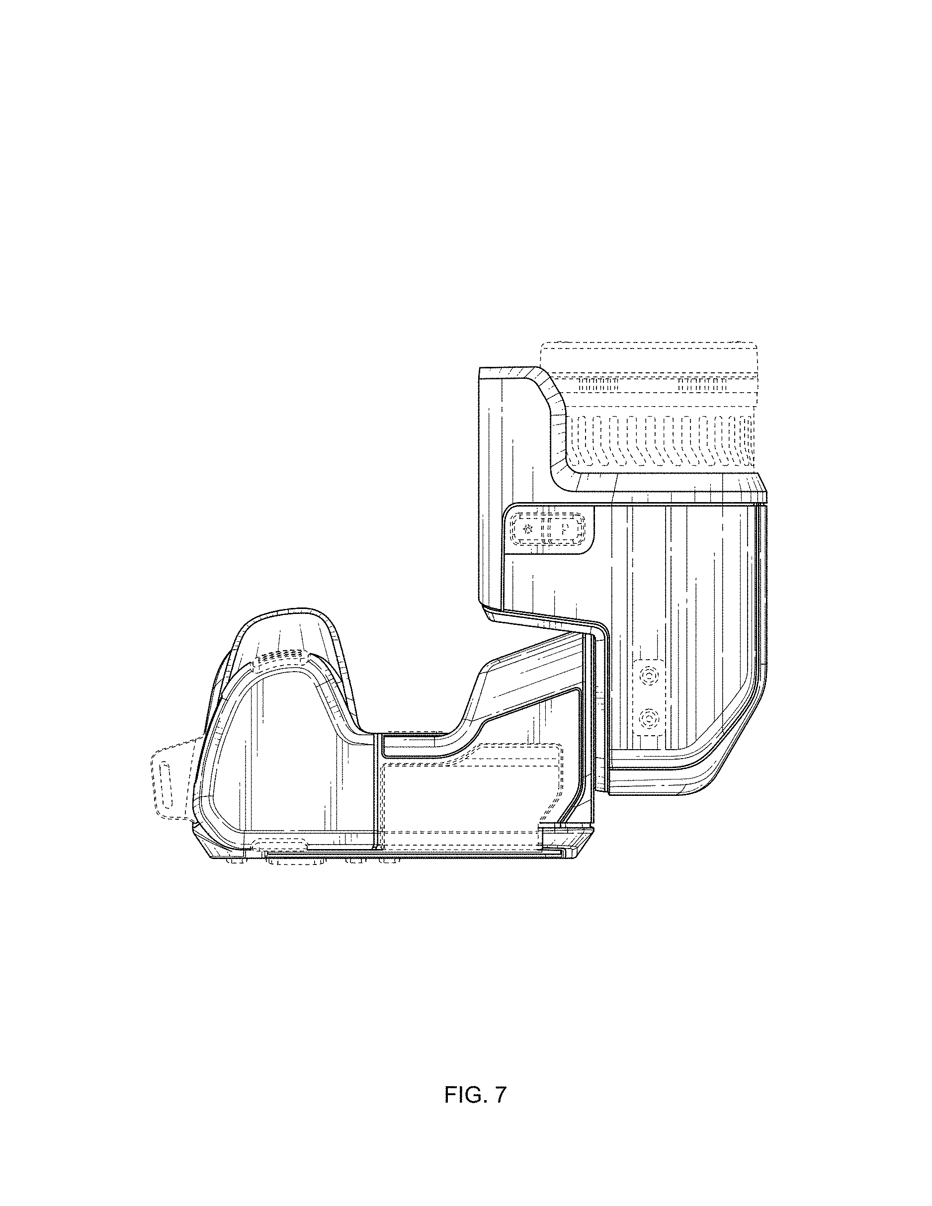
FIG. 7 is a bottom plan view thereof; and
FIG. 8 is a rear, right, and bottom perspective view thereof.
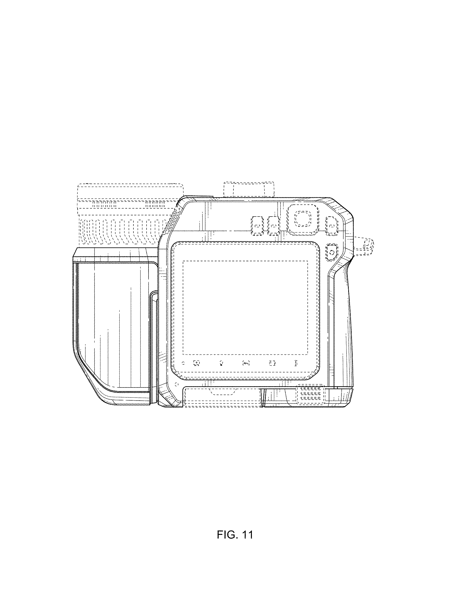
FIG. 9 is a rear, left, and top perspective view of the camera illustrated in a second orientation, wherein a first portion of the camera (e.g., a lens assembly), may be selectively moved to one or more positions relative to a second portion of the camera (e.g., an interactive user interface);
FIG. 10 is a front elevational view thereof;
FIG. 11 is a rear elevational view thereof;
FIG. 12 is a right side view thereof;
FIG. 13 is a left side view thereof;
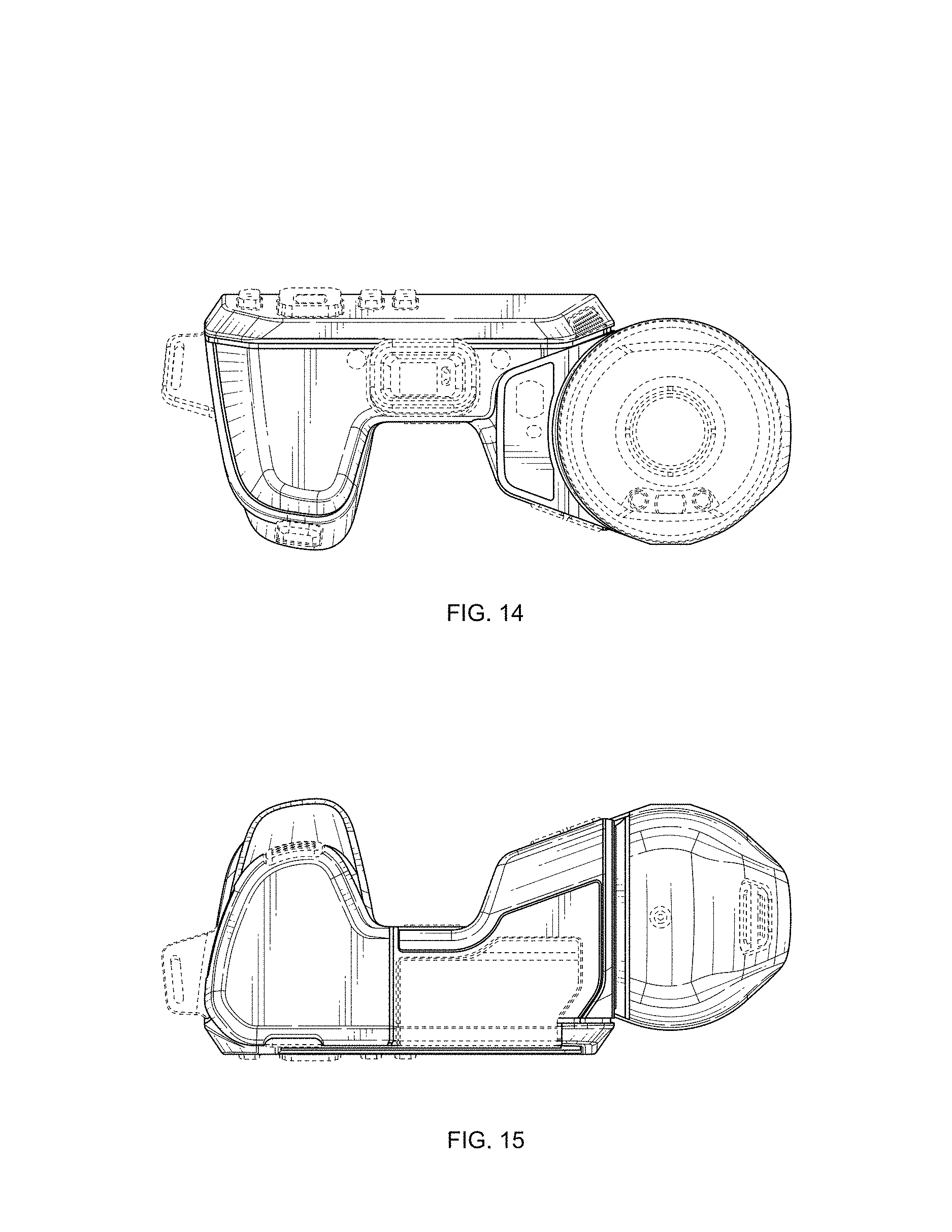
FIG. 14 is a top plan view thereof;
FIG. 15 is a bottom plan view thereof; and,
FIG. 16 is a front, right, and bottom side elevational view thereof.
The broken lines depict portions of the camera in which the design is embodied that form no part of the claimed design.
* * * * *
D00000
D00001
D00002
D00003
D00004
D00005
D00006
D00007
D00008
D00009
D00010
D00011
D00012

D00013
D00014

XML
uspto.report is an independent third-party trademark research tool that is not affiliated, endorsed, or sponsored by the United States Patent and Trademark Office (USPTO) or any other governmental organization. The information provided by uspto.report is based on publicly available data at the time of writing and is intended for informational purposes only.
While we strive to provide accurate and up-to-date information, we do not guarantee the accuracy, completeness, reliability, or suitability of the information displayed on this site. The use of this site is at your own risk. Any reliance you place on such information is therefore strictly at your own risk.
All official trademark data, including owner information, should be verified by visiting the official USPTO website at www.uspto.gov. This site is not intended to replace professional legal advice and should not be used as a substitute for consulting with a legal professional who is knowledgeable about trademark law.