Electrical connector
Stolze
U.S. patent number D848,369 [Application Number D/616,419] was granted by the patent office on 2019-05-14 for electrical connector. This patent grant is currently assigned to WAGO Verwaltungsgesellschaft mit beschraenkter Haftung. The grantee listed for this patent is WAGO Verwaltungsgesellschaft mit beschraenkter Haftung. Invention is credited to Henry Stolze.


| United States Patent | D848,369 |
| Stolze | May 14, 2019 |
Electrical connector
Claims
CLAIM The ornamental design for an electrical connector, as shown and described.
| Inventors: | Stolze; Henry (Bad Frankenhausen, DE) | ||||||||||
|---|---|---|---|---|---|---|---|---|---|---|---|
| Applicant: |
|
||||||||||
| Assignee: | WAGO Verwaltungsgesellschaft mit
beschraenkter Haftung (Minden, DE) |
||||||||||
| Appl. No.: | D/616,419 | ||||||||||
| Filed: | September 6, 2017 |
Foreign Application Priority Data
| Mar 6, 2017 [EM] | 003785401-0007 | |||
| Current U.S. Class: | D13/133; D13/146; D13/147 |
| Current International Class: | 1303 |
| Field of Search: | ;D13/133,146,147,154,184,199 |
References Cited [Referenced By]
U.S. Patent Documents
| D320381 | October 1991 | McGrane |
| D414466 | September 1999 | Bradshaw |
| D593951 | June 2009 | Yoon |
| D612808 | March 2010 | Billerbeck |
| D613693 | April 2010 | Bender |
| D676391 | February 2013 | Gassauer |
| 20 2013 100981 | Jun 2014 | DE | |||
| 002433342-0001 | Mar 2014 | EM | |||
| 002433342-0002 | Mar 2014 | EM | |||
| WO 2015/131215 | Sep 2015 | WO | |||
Attorney, Agent or Firm: Muncy, Geissler, Olds & Lowe, P.C.
Description
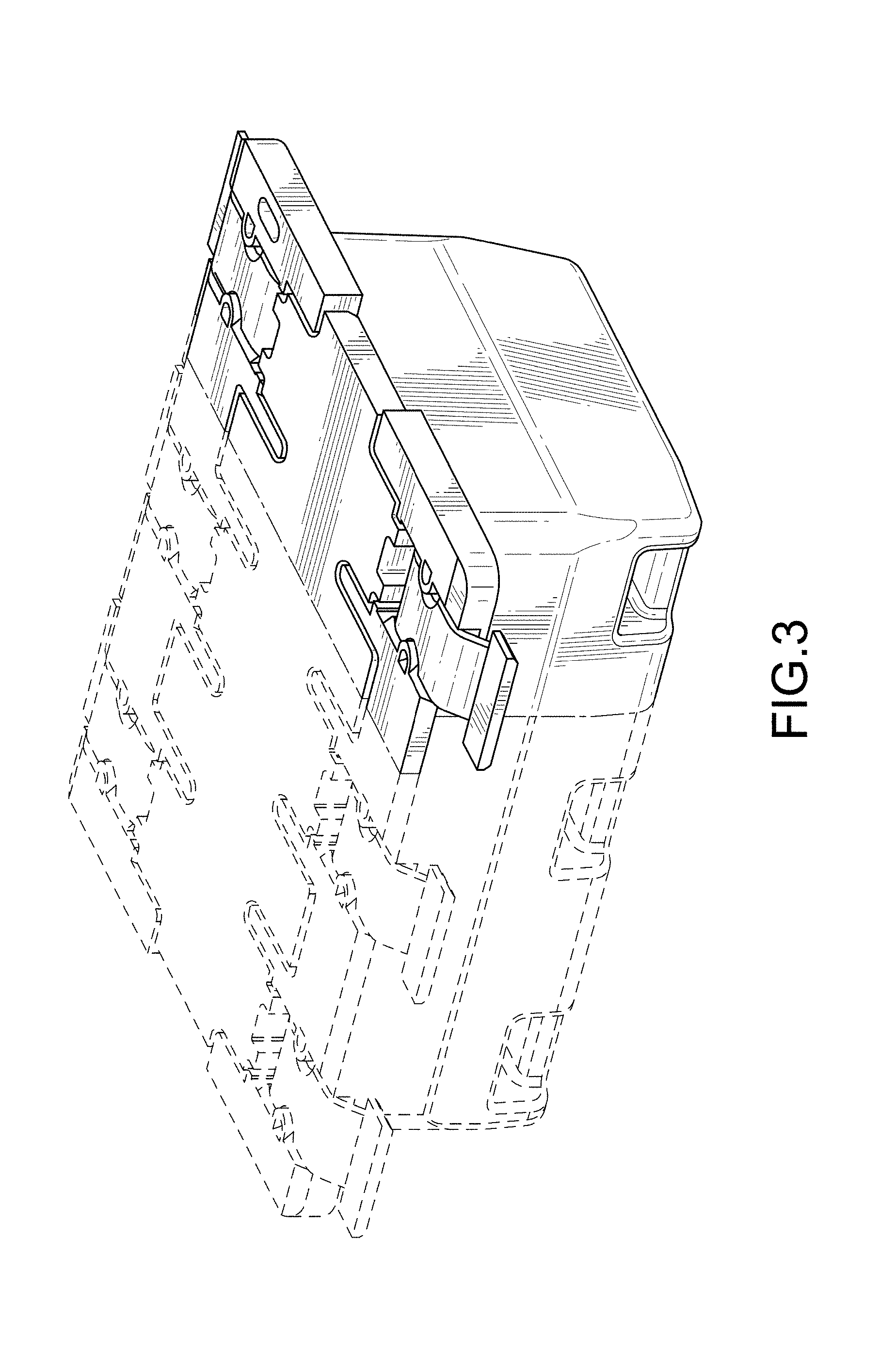
FIG. 1 is a top, front and right side perspective view of an electrical connector showing my invention;
FIG. 2 is a top, rear and left side perspective view thereof;
FIG. 3 is a bottom, rear and right side perspective view thereof;
FIG. 4 is a front elevation view thereof;
FIG. 5 is a rear elevation view thereof;
FIG. 6 is a right side elevation view thereof;
FIG. 7 is a top plan view thereof; and,
FIG. 8 is a bottom plan view thereof.
The even-broken line represents unclaimed environment structure only and forms no part of the claimed design. The dashed-dot lines represent the boundary of the claimed design.
* * * * *
D00000
D00001
D00002
D00003
D00004
D00005
D00006
D00007
D00008
XML
uspto.report is an independent third-party trademark research tool that is not affiliated, endorsed, or sponsored by the United States Patent and Trademark Office (USPTO) or any other governmental organization. The information provided by uspto.report is based on publicly available data at the time of writing and is intended for informational purposes only.
While we strive to provide accurate and up-to-date information, we do not guarantee the accuracy, completeness, reliability, or suitability of the information displayed on this site. The use of this site is at your own risk. Any reliance you place on such information is therefore strictly at your own risk.
All official trademark data, including owner information, should be verified by visiting the official USPTO website at www.uspto.gov. This site is not intended to replace professional legal advice and should not be used as a substitute for consulting with a legal professional who is knowledgeable about trademark law.