Holder used for a cutting tool
Okida , et al.
U.S. patent number D847,885 [Application Number D/564,791] was granted by the patent office on 2019-05-07 for holder used for a cutting tool. This patent grant is currently assigned to Sumitomo Electric Hardmetal Corp.. The grantee listed for this patent is SUMITOMO ELECTRIC HARDMETAL CORP.. Invention is credited to Tomoyuki Fukuyama, Shinya Imamura, Junya Okida, Naoya Tsuda.


| United States Patent | D847,885 |
| Okida , et al. | May 7, 2019 |
Holder used for a cutting tool
Claims
CLAIM The ornamental design for a holder used for a cutting tool, as shown and described.
| Inventors: | Okida; Junya (Itami, JP), Fukuyama; Tomoyuki (Itami, JP), Tsuda; Naoya (Itami, JP), Imamura; Shinya (Itami, JP) | ||||||||||
|---|---|---|---|---|---|---|---|---|---|---|---|
| Applicant: |
|
||||||||||
| Assignee: | Sumitomo Electric Hardmetal
Corp. (Itami-shi, JP) |
||||||||||
| Appl. No.: | D/564,791 | ||||||||||
| Filed: | May 16, 2016 |
Foreign Application Priority Data
| Nov 17, 2015 [JP] | 2015-025658 | |||
| Current U.S. Class: | D15/140; D15/139 |
| Current International Class: | 1509 |
| Field of Search: | ;D8/16,17,18,19,20,70,90,98 ;D15/122,123,124,125,126,127,128,129,130,131,132,133,134,135,136,137,138,139,140,141,142,143 |
References Cited [Referenced By]
U.S. Patent Documents
| 3054308 | September 1962 | Larry |
| D270059 | August 1983 | Wilkins |
| 4412763 | November 1983 | Shallenberger, Jr. |
| 4659264 | April 1987 | Friedline |
| 4844669 | July 1989 | Tsujimura |
| 4854789 | August 1989 | Evseanko, Jr. |
| 5261767 | November 1993 | Tsujimura |
| D370019 | May 1996 | Stewart |
| 5829331 | November 1998 | Mori |
| 6220795 | April 2001 | Matthews |
| 6974282 | December 2005 | King |
| D610177 | February 2010 | Guse |
| D617358 | June 2010 | Guse |
| 8079785 | December 2011 | Nicholas |
| 8465232 | June 2013 | Amstibovitsky |
| D696319 | December 2013 | Tempel |
| D701543 | March 2014 | Mihic |
| 8967921 | March 2015 | Yamaguchi |
| 9956619 | May 2018 | Okamura |
| 2007/0081867 | April 2007 | Murakami |
| 2007/0089574 | April 2007 | Murakami |
| 2015/0056029 | February 2015 | Shimamoto |
| 2015/0266100 | September 2015 | Okamura |
| 04-51306 | Apr 1992 | JP | |||
| 2005-066795 | Mar 2005 | JP | |||
| 2007-075933 | Mar 2007 | JP | |||
Other References
|
"Cutting Tool Geometries Lathe and Mill SME" [online]. KRH Renovations Inc. [Published on Oct. 15, 2015]. Retrieved from the Internet: <https://www.youtube.com/watch?v=bbMbFvsRTJo>. cited by examiner . "12mm 8pcs Lathe cutting tool set" [online]. Aliexpress.com. [Retrieved Dec. 1, 2018]. Retrieved from the Internet: <https://www.aliexpress.com/item/12mm-8pcs-Lathe-cutting-tool-set-the-- most-useful-cutter-set-8pcs-turning-tool-set-to/32786512189.html>. cited by examiner . Notice in Japanese Patent Application No. 2015-025658, dated Aug. 8, 2016. cited by applicant . Machines and Tools, No. 12, vol. 50 (Dec. 1, 2006) (Japan Patent Office, Design Department, known document HA 18027452). cited by applicant. |
Primary Examiner: Anwar; Khawaja
Assistant Examiner: Tehrani; Mojtaba
Attorney, Agent or Firm: Baker Botts L.L.P. Sartori; Michael A.
Description
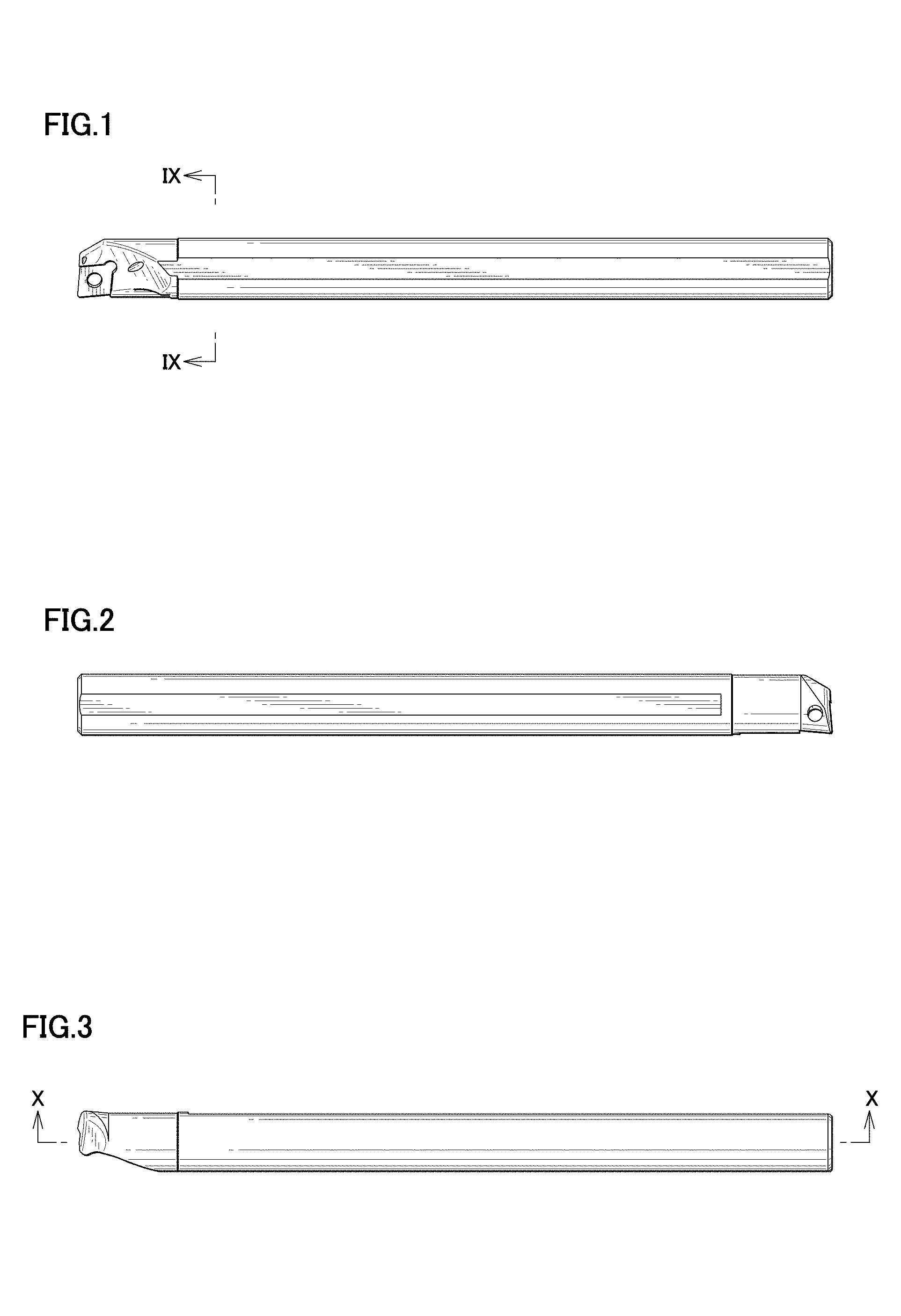
FIG. 1 is a front view of a holder used for a cutting tool, showing our new design;
FIG. 2 is a rear view thereof;
FIG. 3 is a top view thereof;
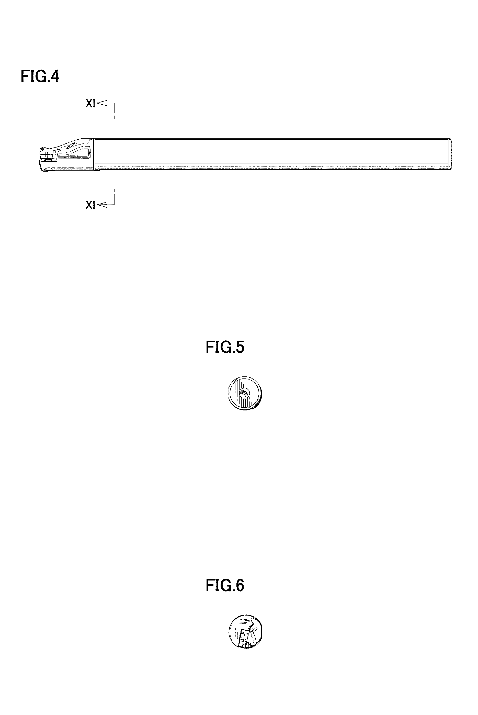
FIG. 4 is a bottom view thereof;
FIG. 5 is a right side view thereof;
FIG. 6 is a left side view thereof;
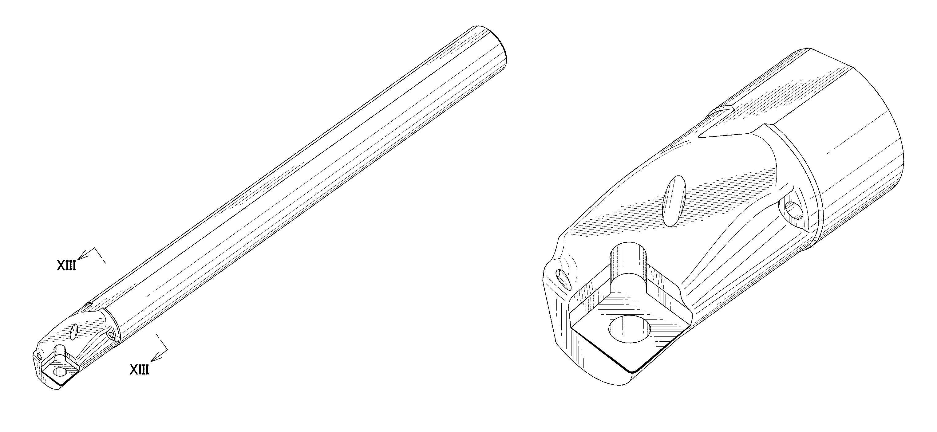
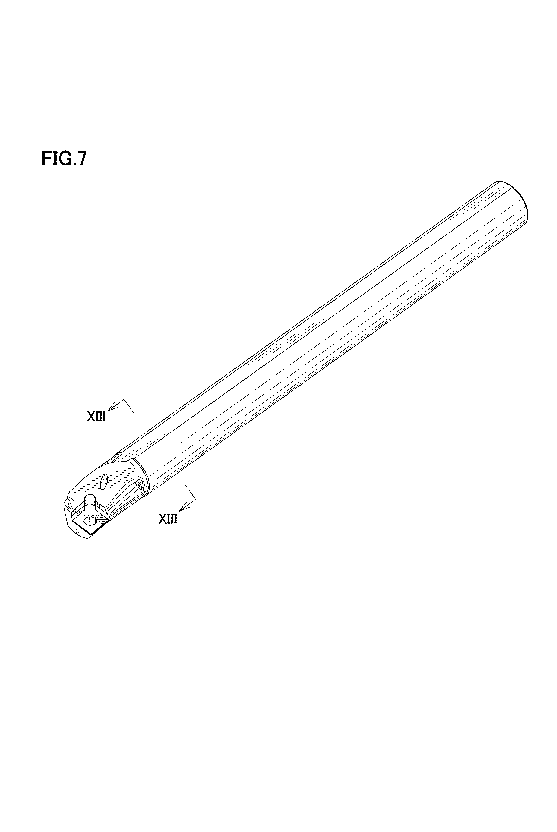
FIG. 7 is a perspective view 1 thereof;
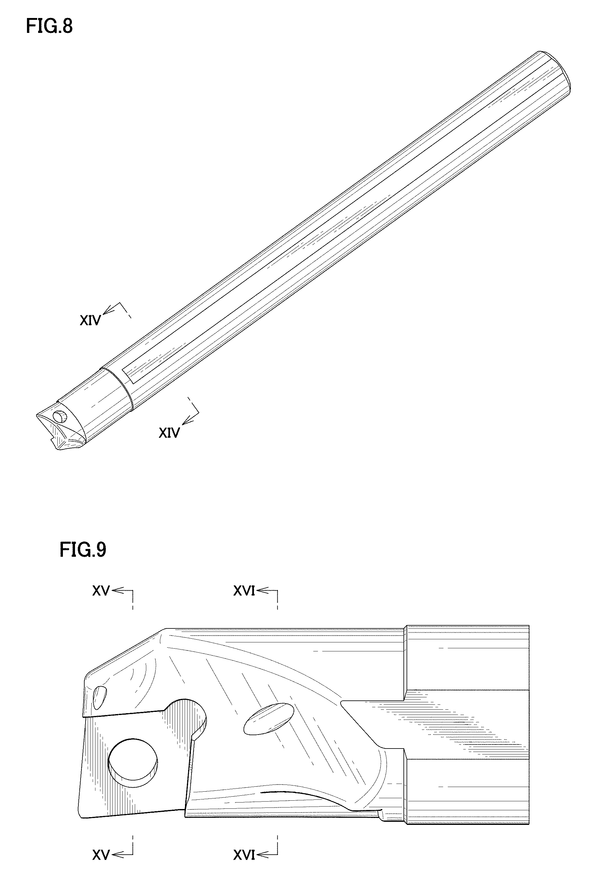
FIG. 8 is a perspective view 2 thereof;
FIG. 9 is an enlarged view of IX-IX portion of FIG. 1;
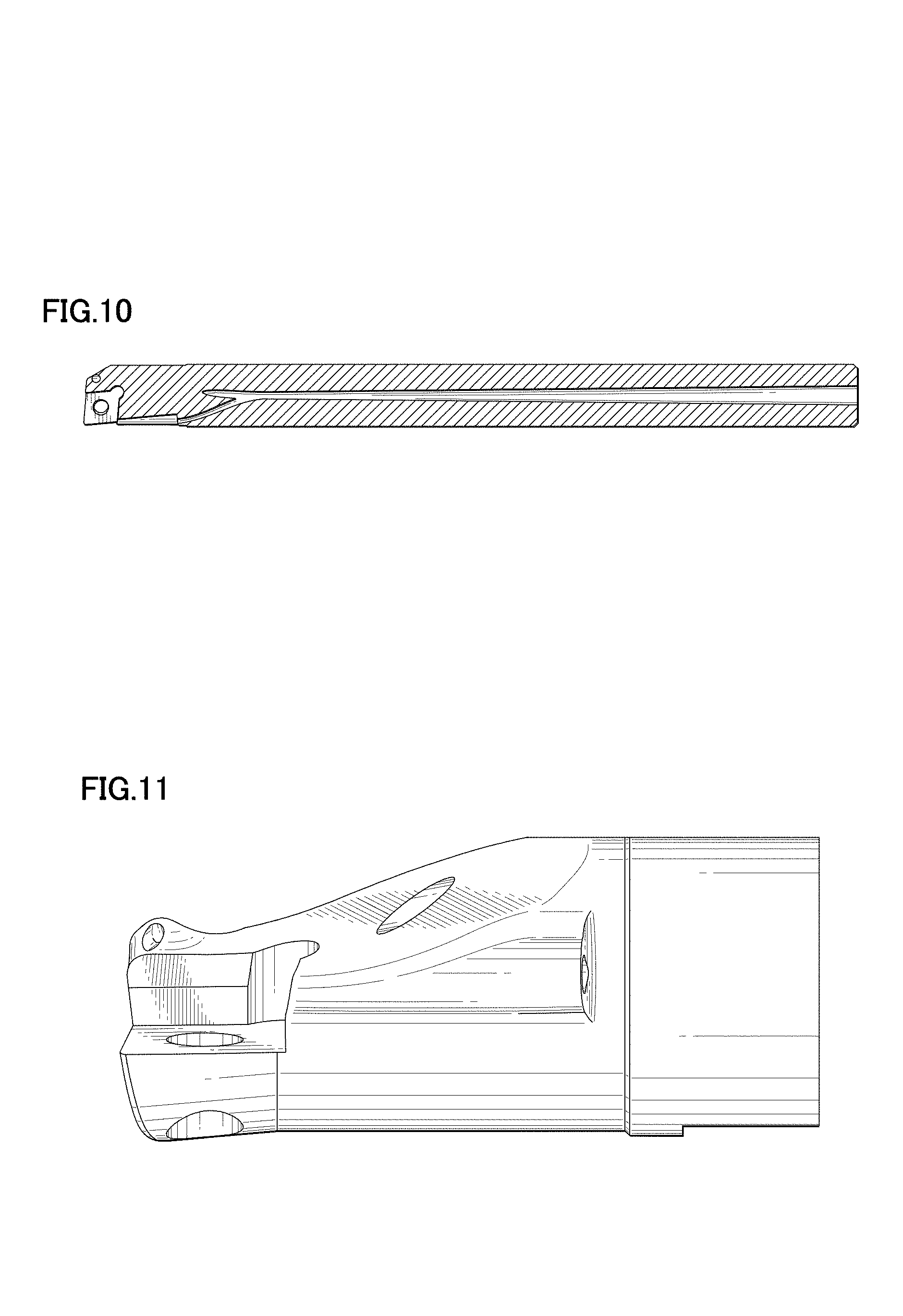
FIG. 10 is a cross sectional view taken along line X-X of FIG. 3;
FIG. 11 is an enlarged view of XI-XI portion of FIG. 4;
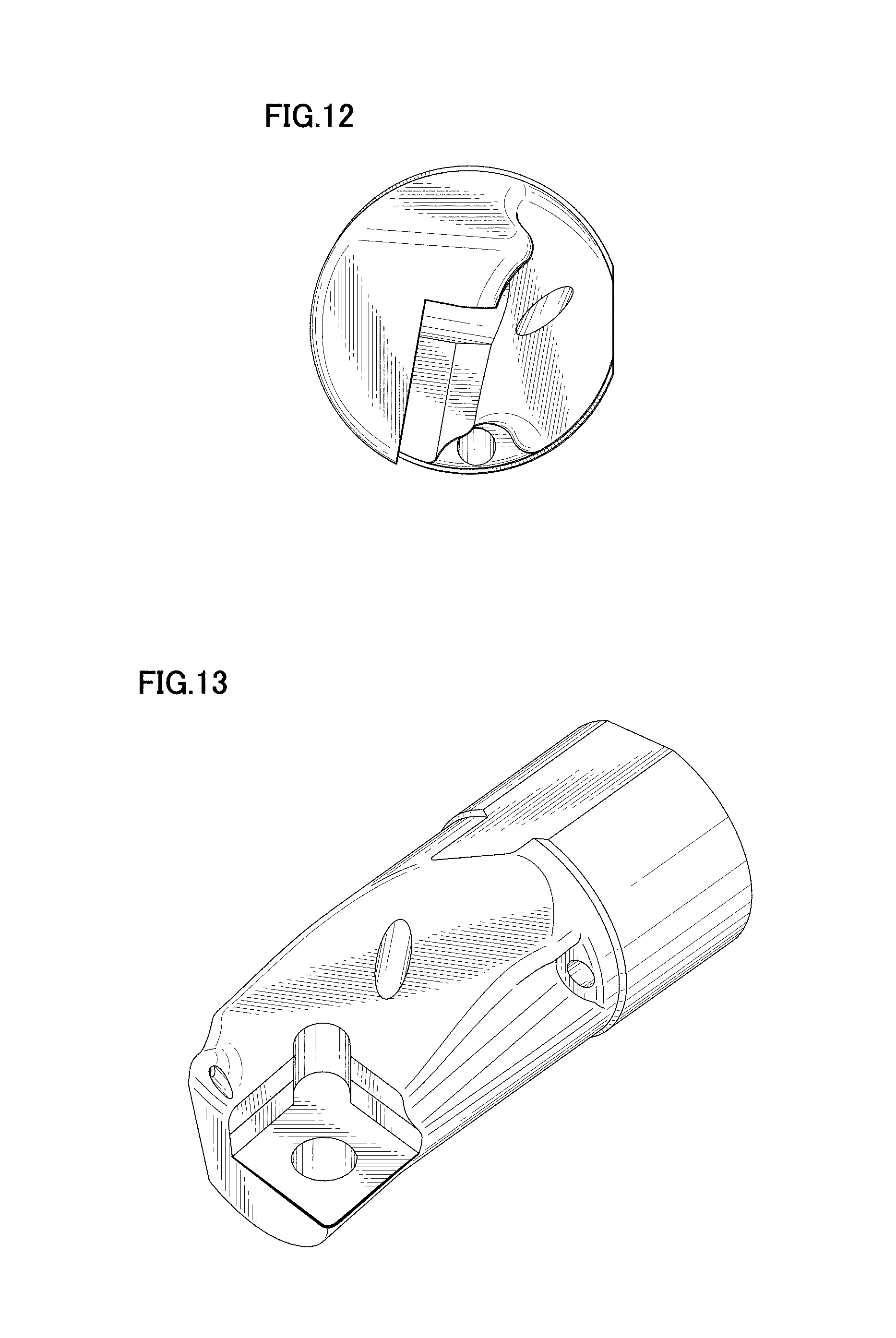
FIG. 12 is an enlarged left side view thereof;
FIG. 13 is an enlarged perspective view of XIII-XIII portion of FIG. 7;
FIG. 14 is an enlarged perspective view of XIV-XIV portion of FIG. 8;
FIG. 15 is a cross sectional view taken along line XV-XV of FIG. 9;
FIG. 16 is a cross sectional view taken along line XVI-XVI of FIG. 9;
FIG. 17 is a referential enlarged view 1 of IX-IX portion of FIG. 1;
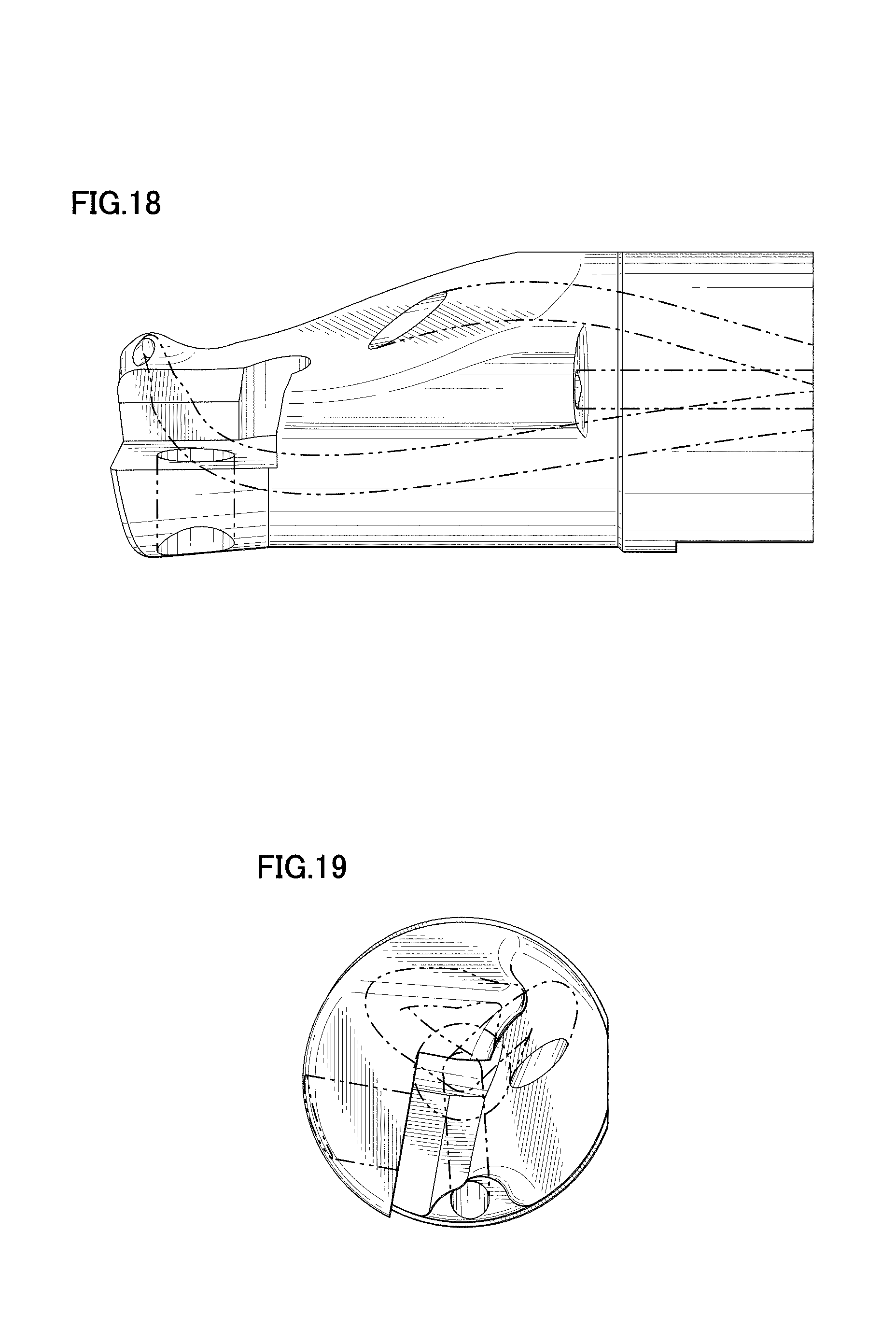
FIG. 18 is a referential enlarged view 2 of XI-XI portion of FIG. 4; and,
FIG. 19 is a referential enlarged left side view thereof.
The two-dot chain lines in the referential enlarged views 1 and 2 and the referential enlarged left side view illustrate flow paths that are provided inside the cutting tool holder.
* * * * *
References
D00000
D00001
D00002
D00003
D00004
D00005
D00006
D00007
D00008
D00009
XML
uspto.report is an independent third-party trademark research tool that is not affiliated, endorsed, or sponsored by the United States Patent and Trademark Office (USPTO) or any other governmental organization. The information provided by uspto.report is based on publicly available data at the time of writing and is intended for informational purposes only.
While we strive to provide accurate and up-to-date information, we do not guarantee the accuracy, completeness, reliability, or suitability of the information displayed on this site. The use of this site is at your own risk. Any reliance you place on such information is therefore strictly at your own risk.
All official trademark data, including owner information, should be verified by visiting the official USPTO website at www.uspto.gov. This site is not intended to replace professional legal advice and should not be used as a substitute for consulting with a legal professional who is knowledgeable about trademark law.