Head mounted audio-visual display system
Natsume , et al.
U.S. patent number D845,296 [Application Number D/621,011] was granted by the patent office on 2019-04-09 for head mounted audio-visual display system. This patent grant is currently assigned to Magic Leap, Inc.. The grantee listed for this patent is MAGIC LEAP, INC.. Invention is credited to Sebastian Gonzalo Arrieta Gunther, Haney Awad, Bradley Fraser, Masamune Kaji, Shigeru Natsume, William Wheeler.


View All Diagrams
| United States Patent | D845,296 |
| Natsume , et al. | April 9, 2019 |
Head mounted audio-visual display system
Claims
CLAIM We claim the ornamental design for a head mounted audio-visual display system, as shown and described.
| Inventors: | Natsume; Shigeru (Weston, FL), Fraser; Bradley (Miami Beach, FL), Awad; Haney (Fort Lauderdale, FL), Arrieta Gunther; Sebastian Gonzalo (Fort Lauderdale, FL), Kaji; Masamune (Plantation, FL), Wheeler; William (Los Angeles, CA) | ||||||||||
|---|---|---|---|---|---|---|---|---|---|---|---|
| Applicant: |
|
||||||||||
| Assignee: | Magic Leap, Inc. (Plantation,
FL) |
||||||||||
| Appl. No.: | D/621,011 | ||||||||||
| Filed: | October 3, 2017 |
| Current U.S. Class: | D14/372 |
| Current International Class: | 1402 |
| Field of Search: | ;D14/372,496,432,371,125,126,129,299 ;D16/300-342 ;351/158,153,144 ;345/7-9,905 ;455/344 ;348/115,53,121,739 |
References Cited [Referenced By]
U.S. Patent Documents
| D746818 | January 2016 | Cho |
| D753211 | April 2016 | DiChiara |
| D754782 | April 2016 | Kokinakis |
| D759015 | June 2016 | Mehin |
| D776111 | January 2017 | Baldassi et al. |
| D777242 | January 2017 | Seo |
| D780752 | March 2017 | Park et al. |
| D781290 | March 2017 | Kim et al. |
| D792400 | July 2017 | Osterhout |
| D795952 | August 2017 | Natsume |
| D796503 | September 2017 | Natsume |
| D796504 | September 2017 | Natsume |
| D796505 | September 2017 | Natsume |
| D796506 | September 2017 | Natsume |
| D797733 | September 2017 | Lee |
| D797735 | September 2017 | Fraser |
| D798862 | October 2017 | Wang |
| D799482 | October 2017 | Thomas |
| D800727 | October 2017 | Mullins |
| D802048 | November 2017 | Lundberg |
| D805072 | December 2017 | Seki |
| D805073 | December 2017 | Yee et al. |
| D806710 | January 2018 | Chen et al. |
| D807882 | January 2018 | Gribetz et al. |
| D810743 | February 2018 | Yee et al. |
| D812612 | March 2018 | Gribetz et al. |
| D815092 | April 2018 | Liao |
| D819636 | June 2018 | Chen et al. |
| D819637 | June 2018 | Chen et al. |
| D820258 | June 2018 | Maw |
| D824905 | August 2018 | Yamada |
Other References
|
Notice of Allowance dated Jul. 31, 2018 for Design U.S. Appl. No. 29/650,868, 12 pages. cited by applicant . Notice of Allowance dated Jul. 31, 2018 for Design U.S. Appl. No. 29/650,872, 12 pages. cited by applicant . Notice of Allowance dated Jul. 31, 2018 for Design U.S. Appl. No. 29/653,570, 8 pages. cited by applicant . Notice of Allowance dated Jul. 31, 2018 for Design U.S. Appl. No. 29/653,573, 8 pages. cited by applicant . Notice of Allowance dated Jul. 31, 2018 for Design U.S. Appl. No. 29/653,575, 8 pages. cited by applicant . Design application specification and drawings for U.S. Appl. No. 29/584,739, filed Nov. 16, 2016, Inventor Michael Slipy, entitled "Head Mounted Audio-Visual Display System" 9 pages. cited by applicant . Design application specification and drawings for U.S. Appl. No. 29/603,737, filed May 11, 2016, Inventor David Charles et al., entitled "Head Mounted Audio-Visual Display System Connection Cable" 25 pages. cited by applicant . Design application specification and drawings for U.S. Appl. No. 29/575,027, filed Aug. 22, 2016, Inventor Bradley Fraser, et al., entitled "Mixed Reality Head Mounted Display" 9 pages. cited by applicant. |
Primary Examiner: Murphy; Austin
Attorney, Agent or Firm: Vista IP Law Group LLP
Description
FIG. 1 is a left front perspective view of a head mounted audio-visual display system according to a first embodiment in a closed configuration showing our design;
FIG. 2 is a right front perspective view of the first embodiment in the closed configuration;
FIG. 3 is a right rear perspective view of the first embodiment in the closed configuration;
FIG. 4 is a left rear perspective view of the first embodiment in the closed configuration;
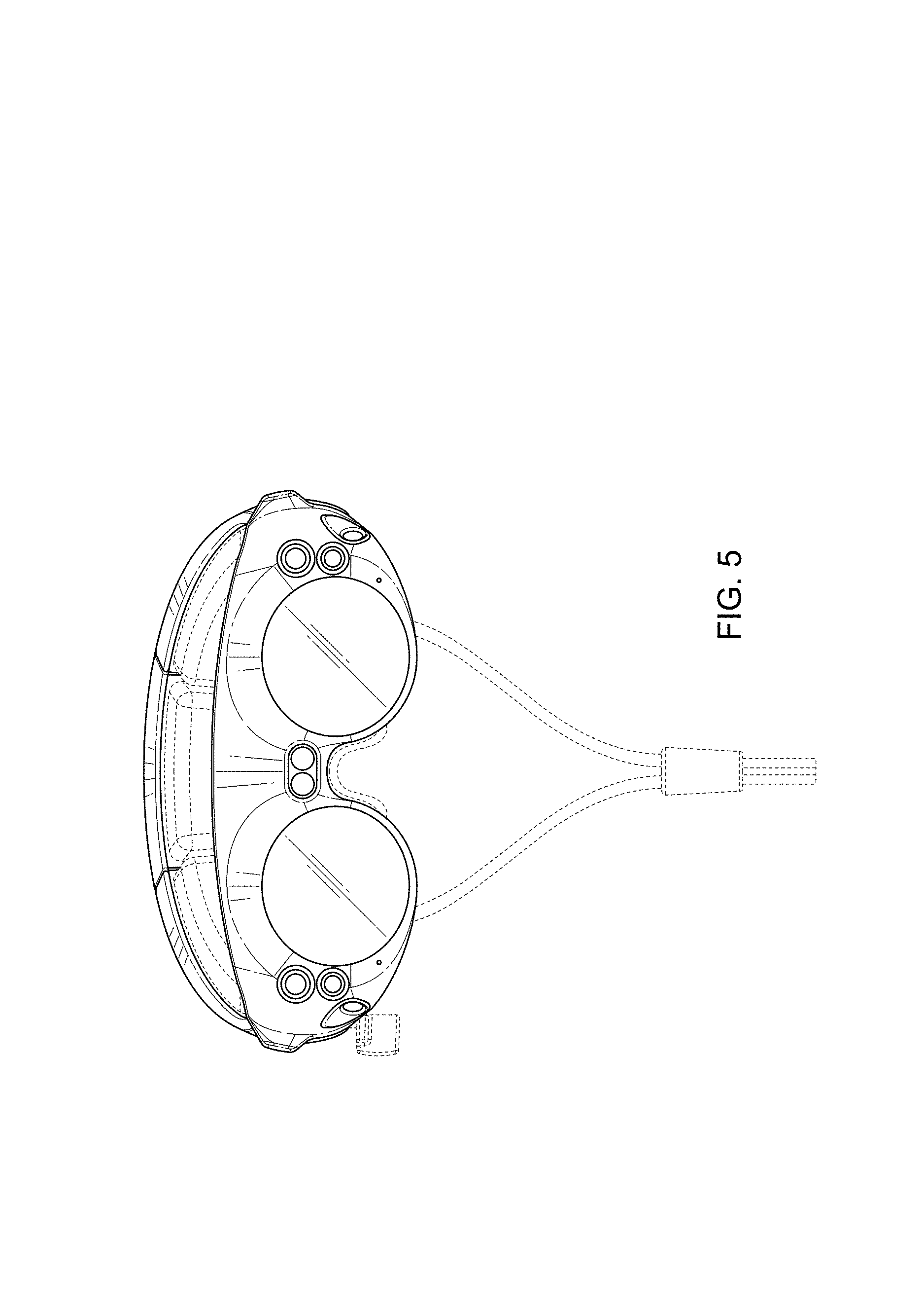
FIG. 5 is a front view of the first embodiment in the closed configuration;
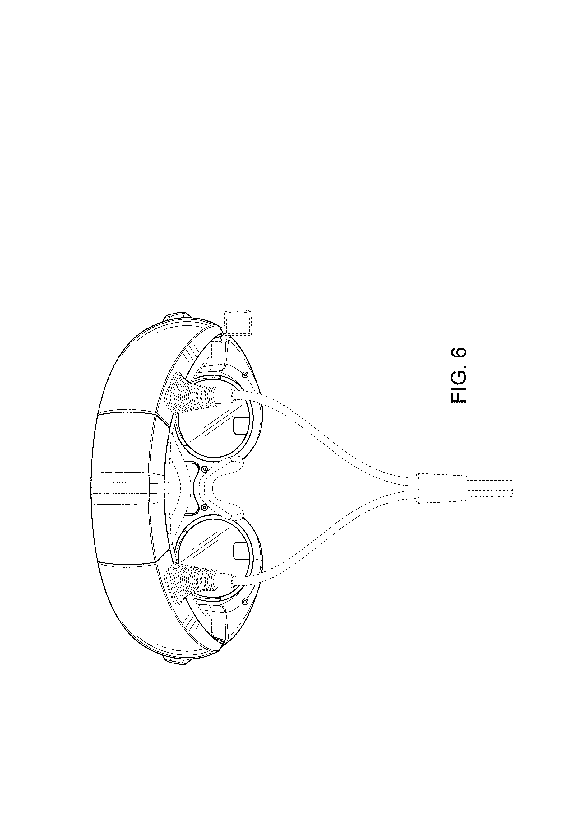
FIG. 6 is a rear view of the first embodiment in the closed configuration;
FIG. 7 is a right side view of the first embodiment in the closed configuration;
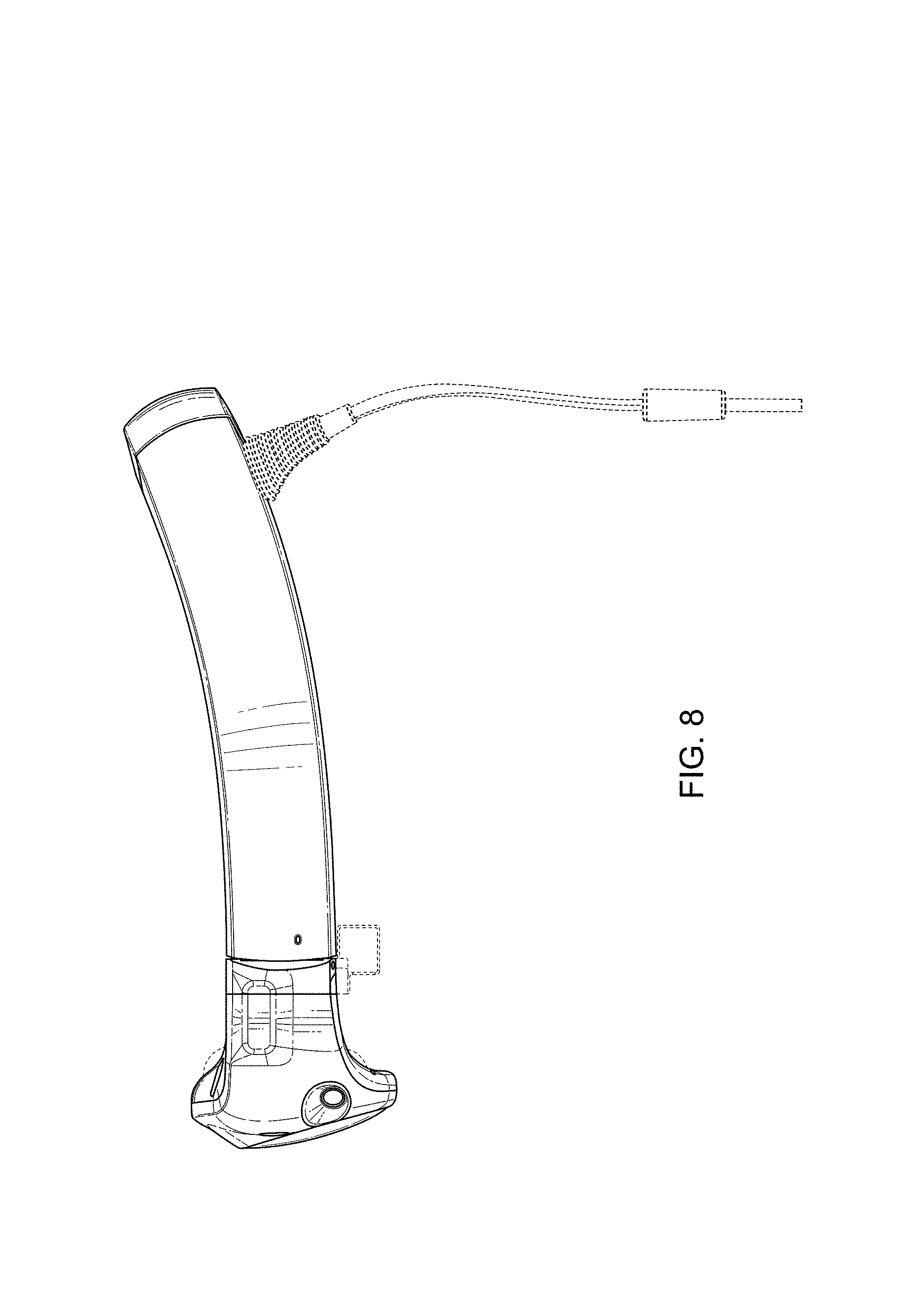
FIG. 8 is a left side view of the first embodiment in the closed configuration;
FIG. 9 is a top view of the first embodiment in the closed configuration;
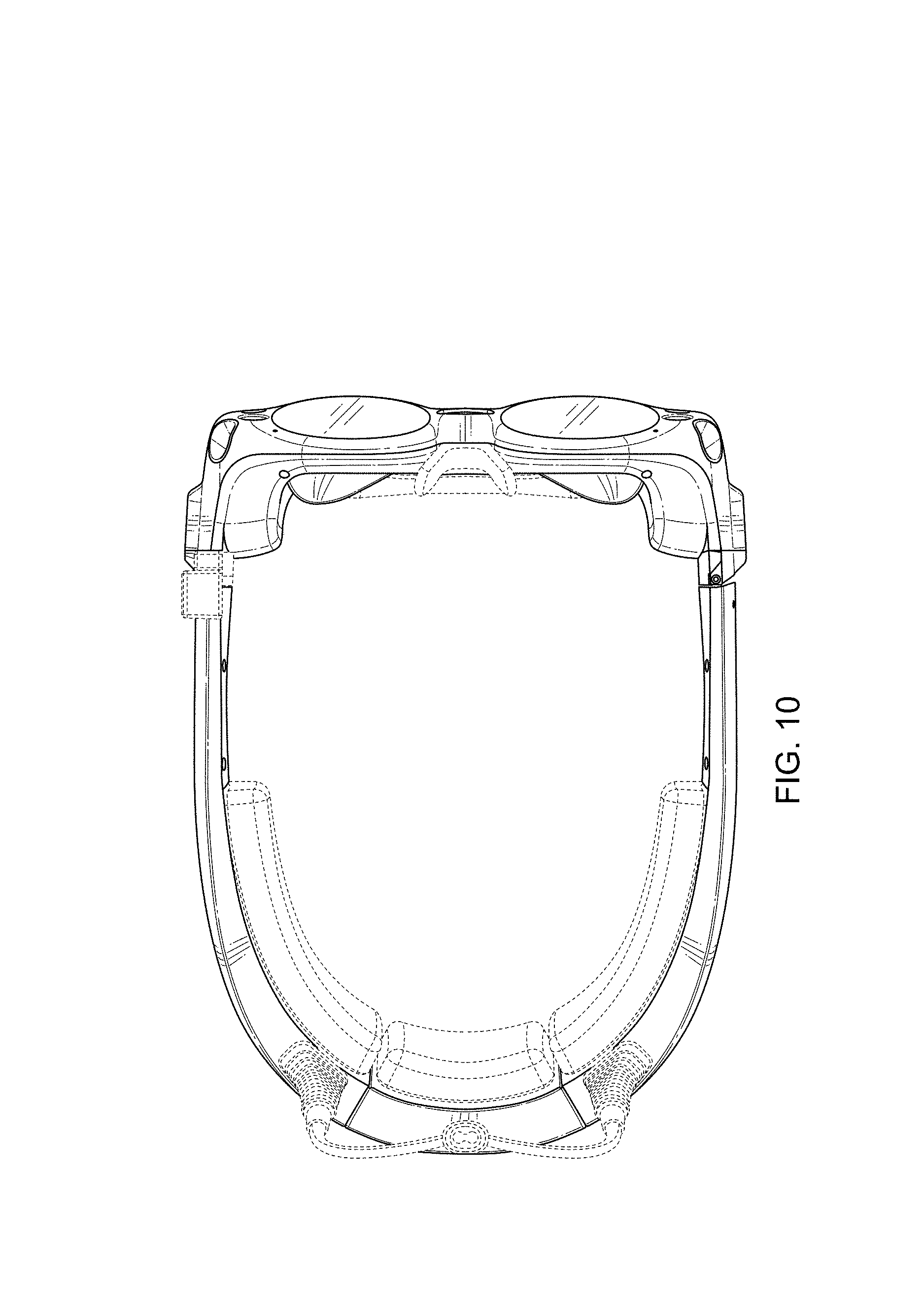
FIG. 10 is a bottom view of the first embodiment in the closed configuration;
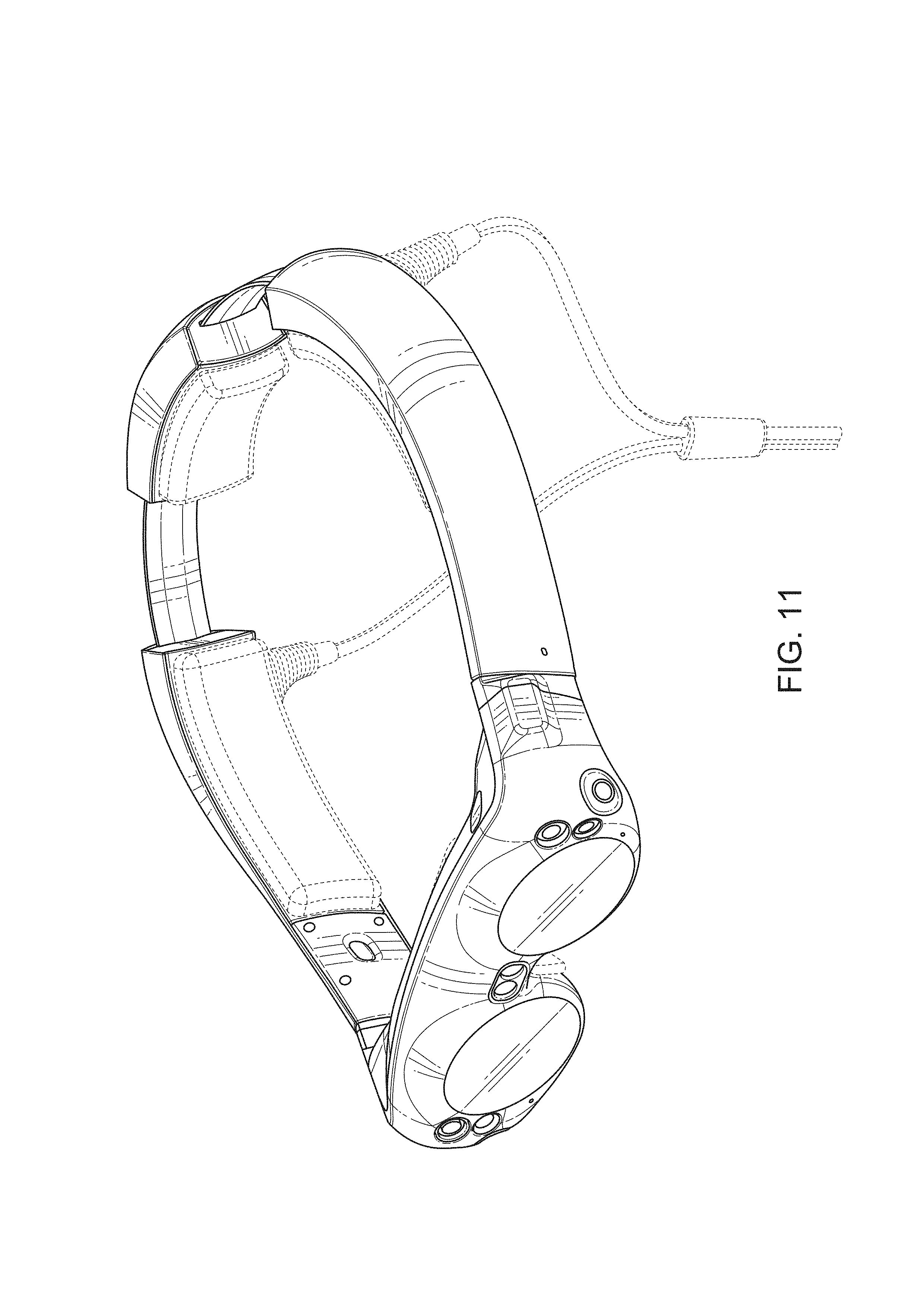
FIG. 11 is a left front perspective view of the first embodiment in an open configuration;
FIG. 12 is a right front perspective view of the first embodiment in the open configuration;
FIG. 13 is a left side view of the first embodiment in the open configuration;
FIG. 14 is a top view of the first embodiment in the open configuration;
FIG. 15 is a rear view of the first embodiment in the open configuration;
FIG. 16 is a left front perspective view of a head mounted audio-visual display system according to a second embodiment in a closed configuration showing our design;
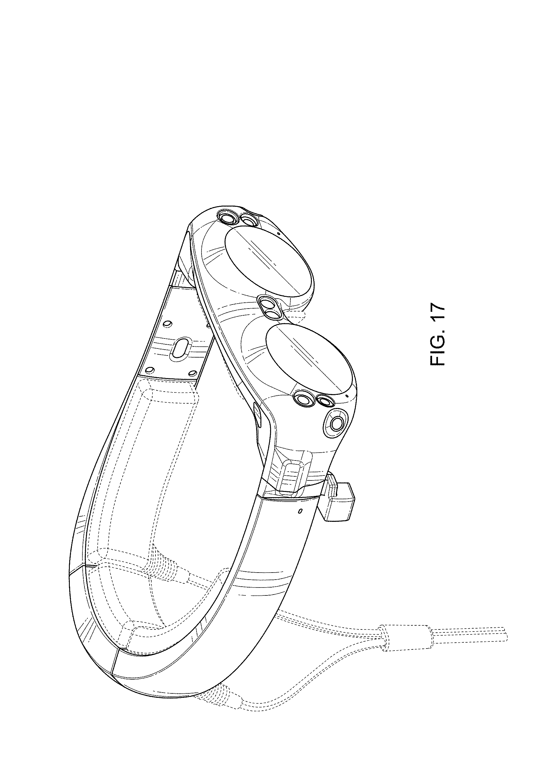
FIG. 17 is a right front perspective view of the second embodiment in the closed configuration;
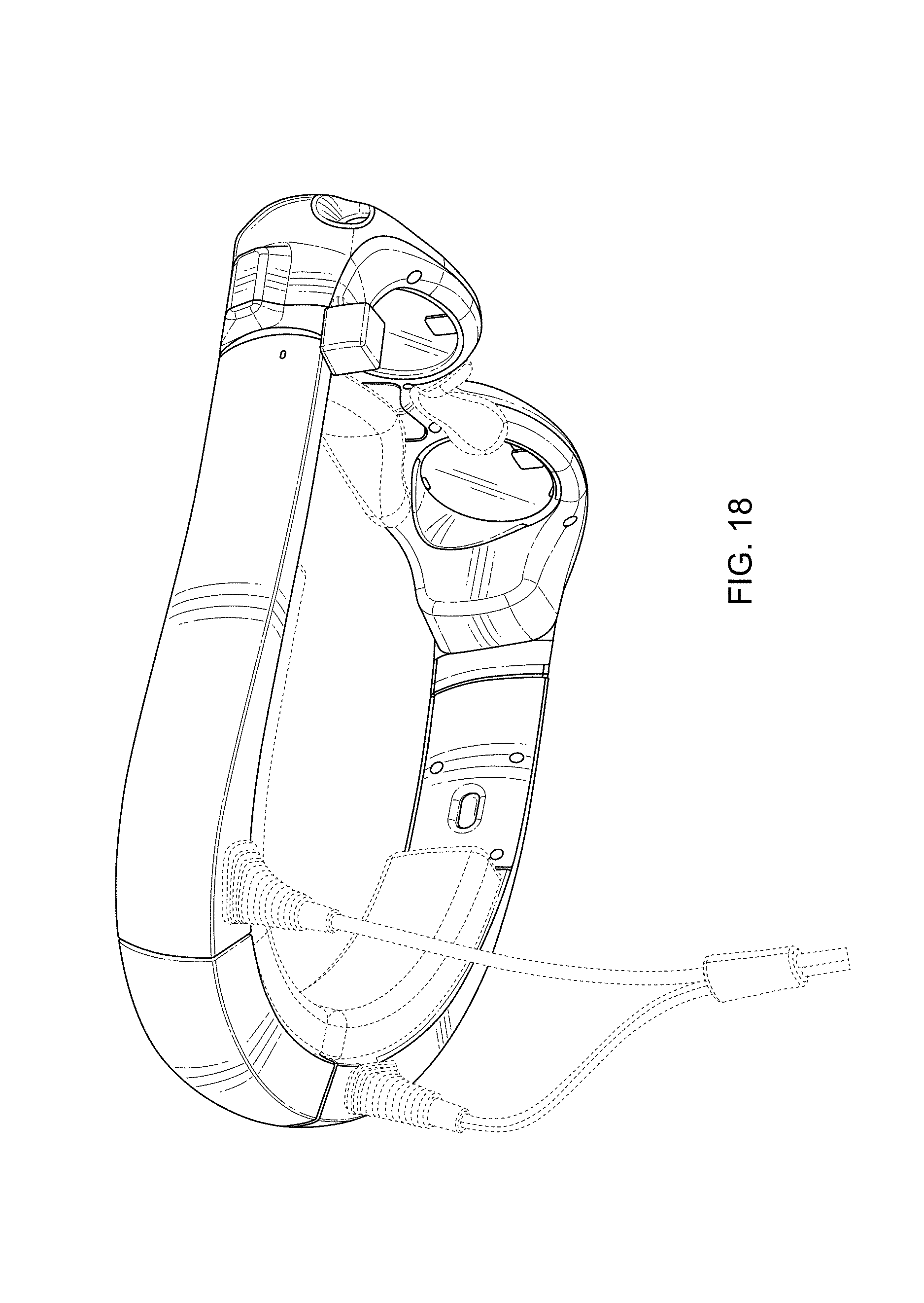
FIG. 18 is a right rear perspective view of the second embodiment in the closed configuration;
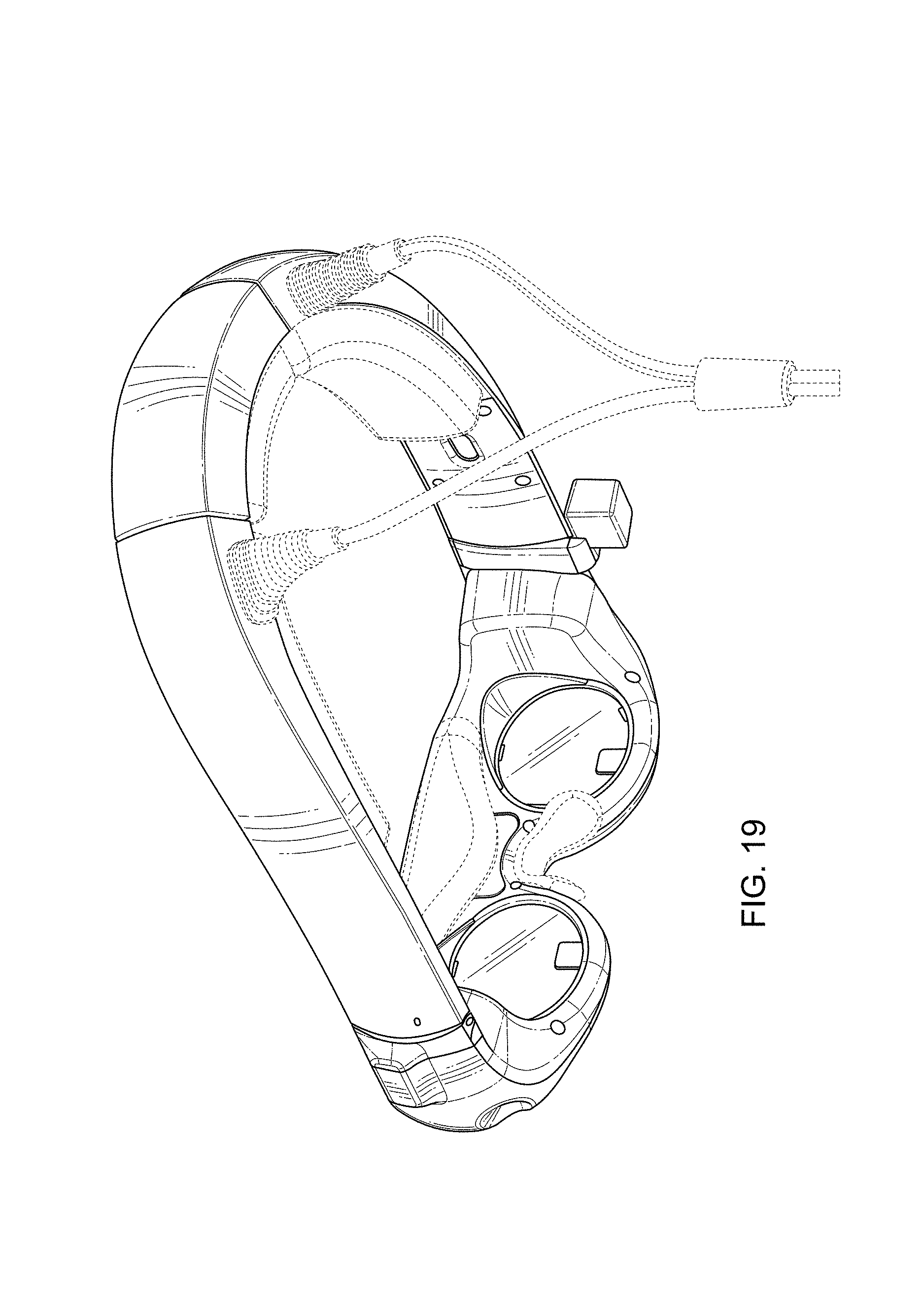
FIG. 19 is a left rear perspective view of the second embodiment in the closed configuration;
FIG. 20 is a front view of the second embodiment in the closed configuration;
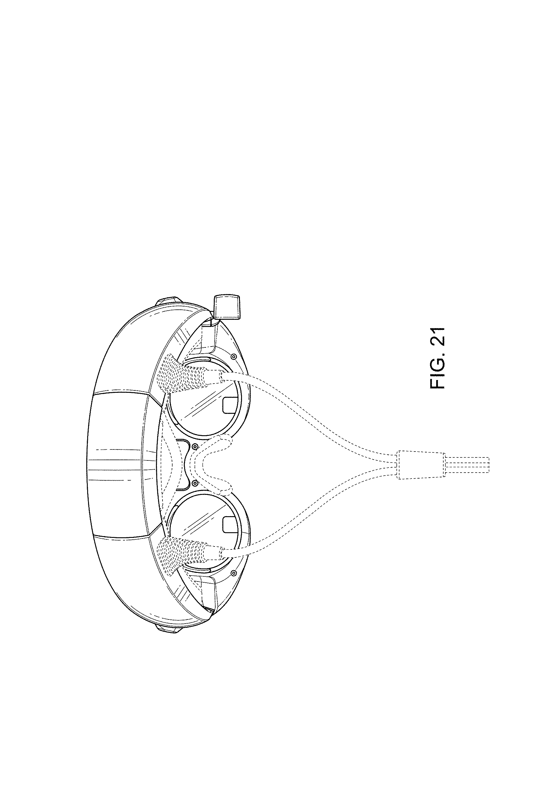
FIG. 21 is a rear view of the second embodiment in the closed configuration;
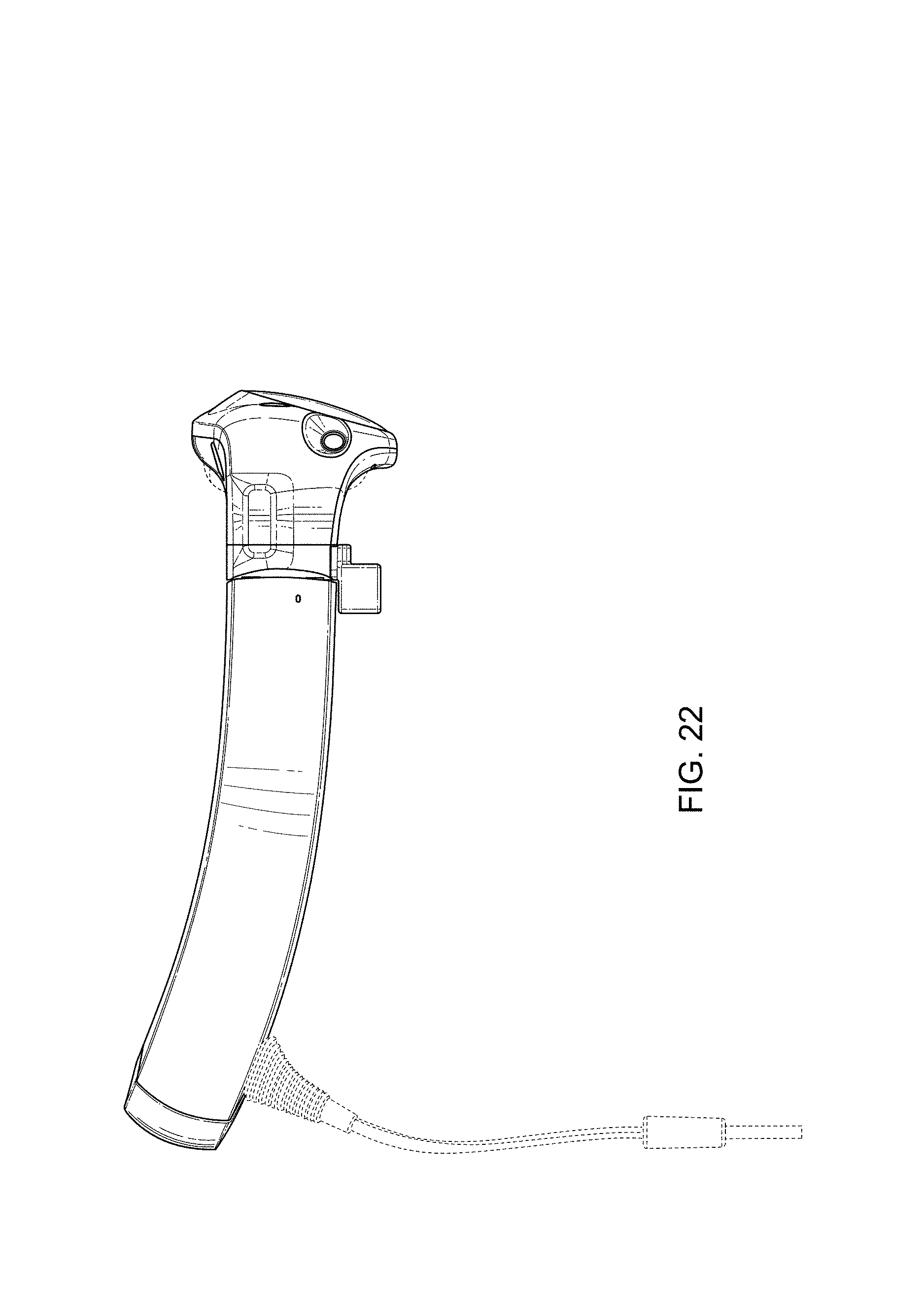
FIG. 22 is a right side view of the second embodiment in the closed configuration;
FIG. 23 is a left side view of the second embodiment in the closed configuration;
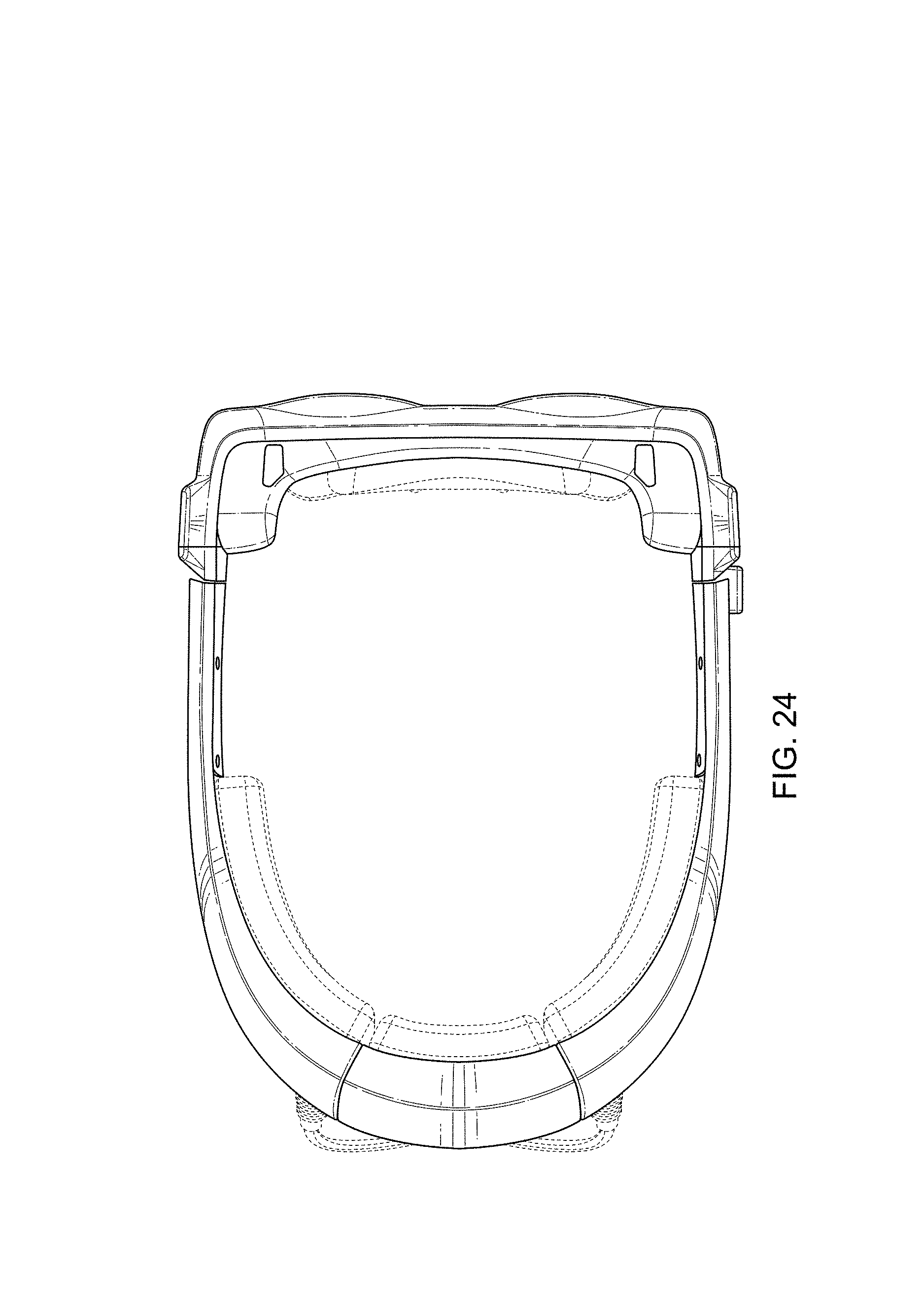
FIG. 24 is a top view of the second embodiment in the closed configuration;
FIG. 25 is a bottom view of the second embodiment in the closed configuration.
FIG. 26 is a right front perspective view of the second embodiment in an open configuration;
FIG. 27 is a right rear view of the second embodiment in the open configuration;
FIG. 28 is a left side view of the second embodiment in the open configuration;
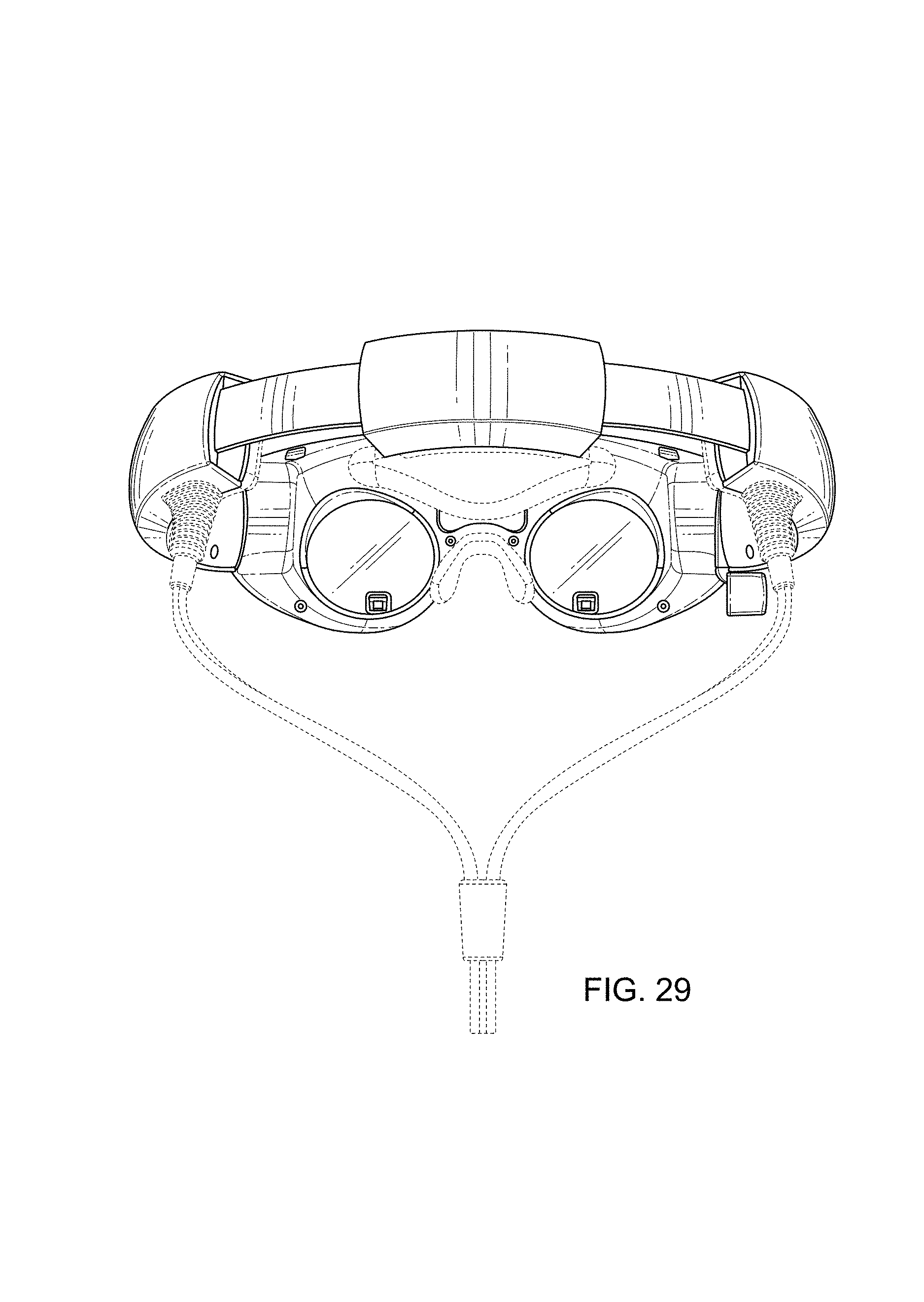
FIG. 29 is a rear view of the second embodiment in the open configuration; and,
FIG. 30 is a bottom view of the second embodiment in the open configuration.
The broken lines depicting various removable optional components of head mounted audio-visual display systems are included for the purpose of illustrating environmental structure and form no part of the claimed design.
* * * * *
D00000
D00001
D00002
D00003
D00004
D00005
D00006
D00007
D00008
D00009
D00010
D00011
D00012

D00013

D00014

D00015

D00016

D00017
D00018
D00019
D00020

D00021
D00022
D00023

D00024
D00025

D00026

D00027

D00028

D00029
D00030

XML
uspto.report is an independent third-party trademark research tool that is not affiliated, endorsed, or sponsored by the United States Patent and Trademark Office (USPTO) or any other governmental organization. The information provided by uspto.report is based on publicly available data at the time of writing and is intended for informational purposes only.
While we strive to provide accurate and up-to-date information, we do not guarantee the accuracy, completeness, reliability, or suitability of the information displayed on this site. The use of this site is at your own risk. Any reliance you place on such information is therefore strictly at your own risk.
All official trademark data, including owner information, should be verified by visiting the official USPTO website at www.uspto.gov. This site is not intended to replace professional legal advice and should not be used as a substitute for consulting with a legal professional who is knowledgeable about trademark law.