Rocker switch with rectangular illumination ring
Fasano , et al.
U.S. patent number D845,255 [Application Number D/613,034] was granted by the patent office on 2019-04-09 for rocker switch with rectangular illumination ring. This patent grant is currently assigned to Carling Technologies, Inc.. The grantee listed for this patent is Carling Technologies, Inc.. Invention is credited to Michael Fasano, Sean McDonnell, Walter A. Sadowski, Brian Thomas Stuckman.


| United States Patent | D845,255 |
| Fasano , et al. | April 9, 2019 |
Rocker switch with rectangular illumination ring
Claims
CLAIM The ornamental design for a rocker switch with rectangular illumination ring, as shown and described.
| Inventors: | Fasano; Michael (Watertown, CT), Sadowski; Walter A. (Newington, CT), Stuckman; Brian Thomas (Bristol, CT), McDonnell; Sean (Plainville, CT) | ||||||||||
|---|---|---|---|---|---|---|---|---|---|---|---|
| Applicant: |
|
||||||||||
| Assignee: | Carling Technologies, Inc.
(Plainville, CT) |
||||||||||
| Appl. No.: | D/613,034 | ||||||||||
| Filed: | August 7, 2017 |
| Current U.S. Class: | D13/169 |
| Current International Class: | 1303 |
| Field of Search: | ;D13/169,174,177 |
References Cited [Referenced By]
U.S. Patent Documents
| 4539446 | September 1985 | Raab |
| 5213204 | May 1993 | Sommer |
| 6794592 | September 2004 | Liu |
| D589463 | March 2009 | Sykes |
| D658138 | April 2012 | Harada |
| 8674221 | March 2014 | Yang |
| 9109792 | August 2015 | Yang |
| 9478370 | October 2016 | Weiss |
| D777686 | January 2017 | Huynh |
| 9916631 | March 2018 | Hill |
| 9916948 | March 2018 | Brudzynsky |
| 2018/0130616 | May 2018 | Fasano |
Attorney, Agent or Firm: Forge IP, PLLC
Description
FIG. 1 is a front perspective view of a rocker switch with a rectangular illumination ring with the switch in neutral position in accordance with our new design, wherein the illuminating ring is not illuminated;
FIG. 2 is a side elevational view thereof; the other side elevational view being a mirror image thereof;
FIG. 3 is a top plan view thereof;
FIG. 4 is an end elevational view thereof; the other end being a mirror image thereof;
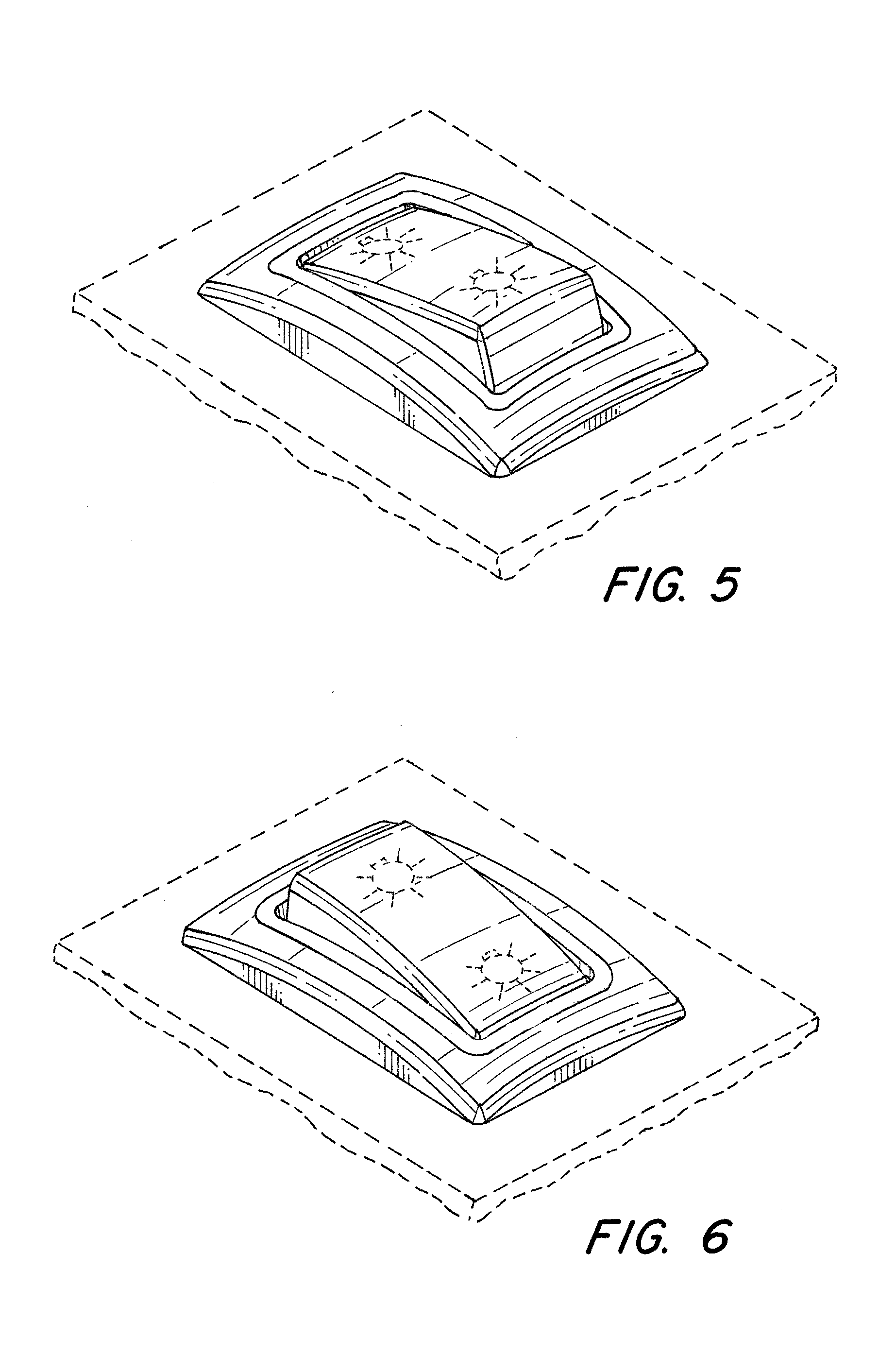
FIG. 5 is a front perspective view with the switch in a first on position;
FIG. 6 is a front perspective view with the switch in a second on position;
FIG. 7 is a side elevational view with the switch in the first on position;
FIG. 8 is a front perspective view of the rocker switch with the rectangular illumination ring with the switch in neutral position thereof, wherein the illuminating region is in illuminated state;
FIG. 9 is a side elevational view thereof; the other side elevational view being a mirror image thereof;
FIG. 10 is a top plan view thereof;
FIG. 11 is an end elevational view thereof; the other end being a mirror image thereof;
FIG. 12 is a front perspective view with the switch in a first on position;
FIG. 13 is a front perspective view with the switch in a second on position; and,
FIG. 14 is a side elevational view with the switch in the first on position.
The broken lines in FIGS. 1-14 are for the purpose of illustrating the boundary of the claimed design and form no part of the claimed design. The radiating lines in FIGS. 8-14 indicate illumination.
* * * * *
D00000
D00001
D00002
D00003
D00004
D00005
D00006
D00007
D00008
XML
uspto.report is an independent third-party trademark research tool that is not affiliated, endorsed, or sponsored by the United States Patent and Trademark Office (USPTO) or any other governmental organization. The information provided by uspto.report is based on publicly available data at the time of writing and is intended for informational purposes only.
While we strive to provide accurate and up-to-date information, we do not guarantee the accuracy, completeness, reliability, or suitability of the information displayed on this site. The use of this site is at your own risk. Any reliance you place on such information is therefore strictly at your own risk.
All official trademark data, including owner information, should be verified by visiting the official USPTO website at www.uspto.gov. This site is not intended to replace professional legal advice and should not be used as a substitute for consulting with a legal professional who is knowledgeable about trademark law.