Support for a hair care appliance
Teyu , et al.
U.S. patent number D843,654 [Application Number D/618,538] was granted by the patent office on 2019-03-19 for support for a hair care appliance. This patent grant is currently assigned to Dyson Technology Limited. The grantee listed for this patent is Dyson Technology Limited. Invention is credited to Stephen Benjamin Courtney, William John Darvill, Alexander Stuart Knox, Paul Andrew McLuckie, Mon Shy Teyu.


| United States Patent | D843,654 |
| Teyu , et al. | March 19, 2019 |
Support for a hair care appliance
Claims
CLAIM We claim the ornamental design for a support for a hair care appliance, as shown and described.
| Inventors: | Teyu; Mon Shy (Johor Bahru, MY), McLuckie; Paul Andrew (Bristol, GB), Knox; Alexander Stuart (Swindon, GB), Courtney; Stephen Benjamin (Gloucester, GB), Darvill; William John (Singapore, SG) | ||||||||||
|---|---|---|---|---|---|---|---|---|---|---|---|
| Applicant: |
|
||||||||||
| Assignee: | Dyson Technology Limited
(Malmesbury, Wiltshire, GB) |
||||||||||
| Appl. No.: | D/618,538 | ||||||||||
| Filed: | September 21, 2017 |
Foreign Application Priority Data
| Mar 22, 2017 [GB] | 6009492 | |||
| Current U.S. Class: | D28/18 |
| Current International Class: | 2803 |
| Field of Search: | ;D28/10,12,13,14,15,16,17,18,20,81,82,83,84 |
References Cited [Referenced By]
U.S. Patent Documents
| 5590475 | January 1997 | Andis |
| D378892 | April 1997 | Garcia |
| 7506849 | March 2009 | Koster |
| D601300 | September 2009 | Burk |
| 7748583 | July 2010 | Woltman |
| D645462 | September 2011 | Choi |
| D669636 | October 2012 | Goodman |
| D717289 | November 2014 | Takabatake |
| D748334 | January 2016 | Goodman |
| D752595 | March 2016 | Heckler |
| D769235 | October 2016 | Li |
| D806436 | January 2018 | Bartolomucci |
| 9968188 | May 2018 | Floersch |
| D828843 | September 2018 | Foldvary |
| 2004/0065688 | April 2004 | Duquet |
| 2011/0057082 | March 2011 | West |
Other References
|
Dyson Supersonic.TM. White/Silver with Presentation Stand, posted .COPYRGT. 2017 [online], retrieved Oct. 9, 2018, retrieved from internet , <https://www.metro.com.sg/product/dyson-supersonic-hair-dryer-whites- ilver-with-metal-stand?r=c-5556>. cited by examiner . Dyson Supersonic.TM. hair dryer stand, no posting date given [online], retrieved Oct. 9, 2018, retrieved from internet, <https://shop.dyson.com.sg/haircare/dyson-supersonic-hair-dryer-stand-- 968685-02>. cited by examiner. |
Primary Examiner: Fox; Barbara
Assistant Examiner: Smith; Messina L
Attorney, Agent or Firm: Morrison & Foerster LLP
Description
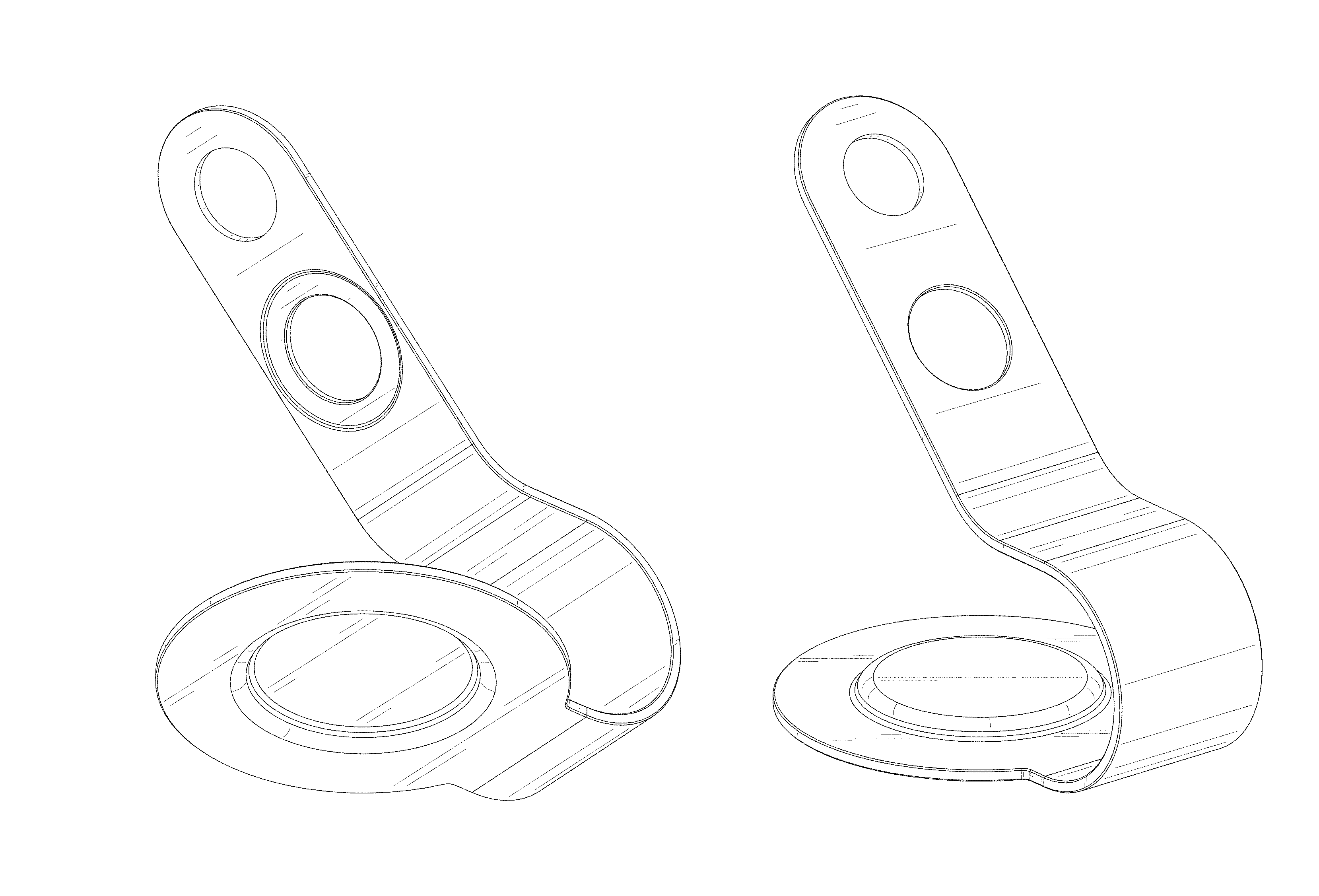
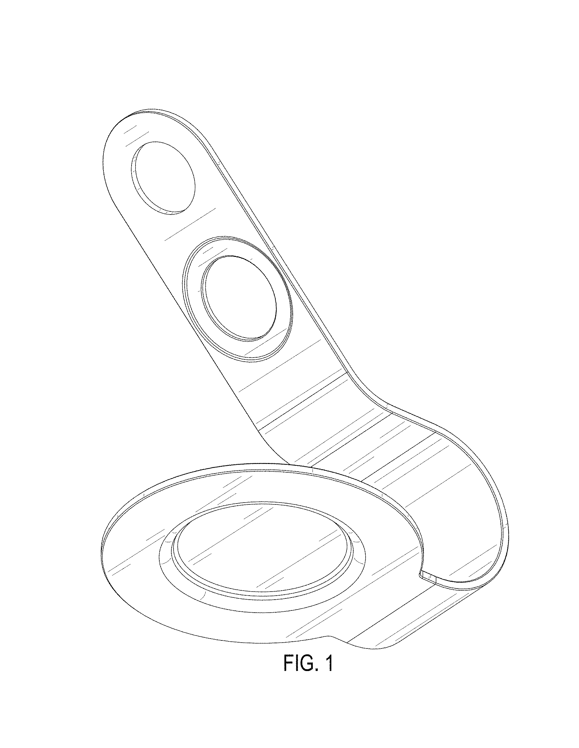
FIG. 1 is a front perspective view of a support for a hair care appliance showing our new design;
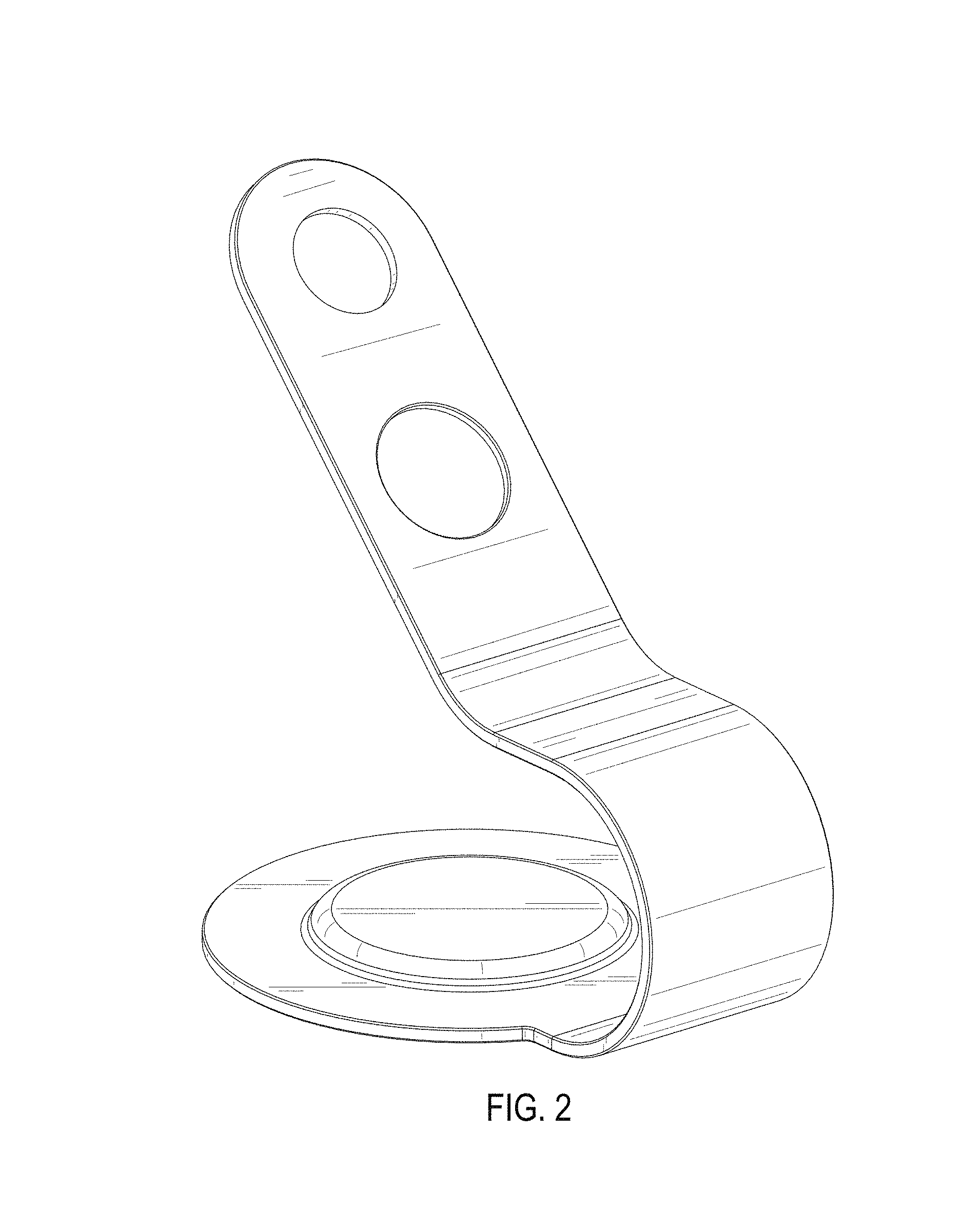
FIG. 2 is a rear perspective view thereof;
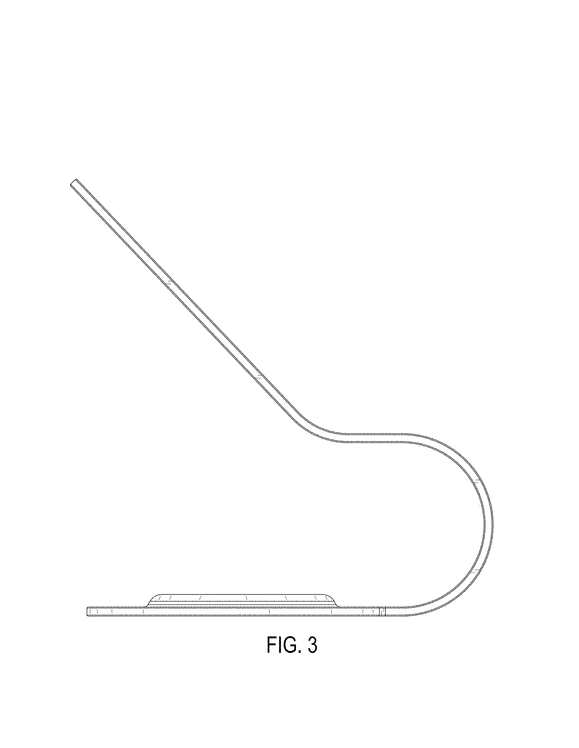
FIG. 3 is a side view thereof;
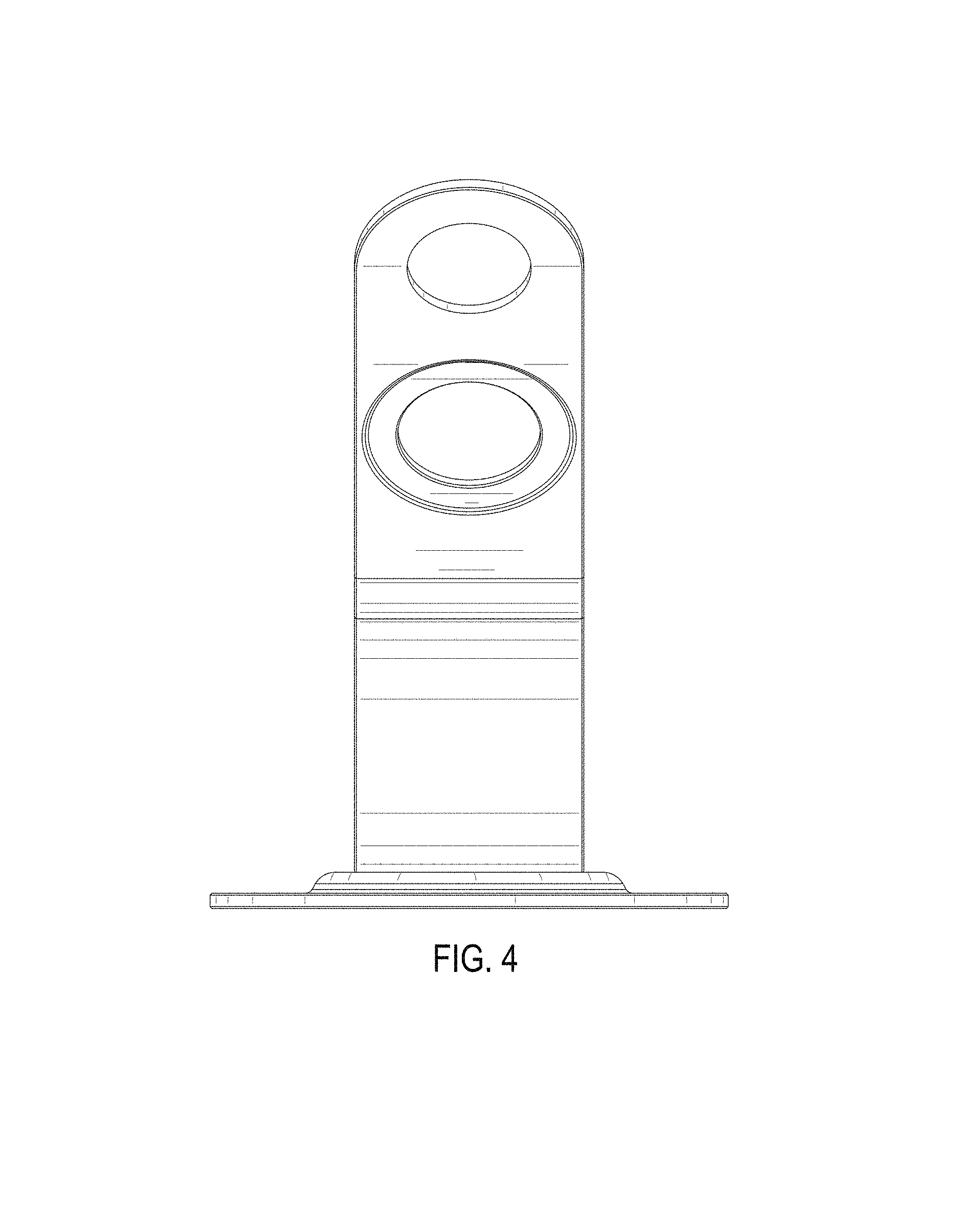
FIG. 4 is a front view thereof;
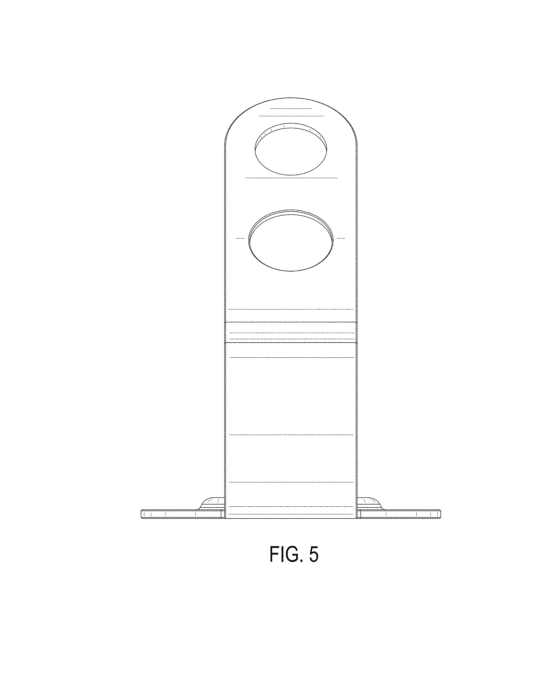
FIG. 5 is a rear view thereof;
FIG. 6 is a top view thereof; and,
FIG. 7 is a bottom view thereof.
The view opposite the side view of FIG. 3 is a mirror image of the side view of FIG. 3 and, therefore, is omitted herein.
* * * * *
References
D00000
D00001
D00002
D00003
D00004
D00005
D00006
D00007
XML
uspto.report is an independent third-party trademark research tool that is not affiliated, endorsed, or sponsored by the United States Patent and Trademark Office (USPTO) or any other governmental organization. The information provided by uspto.report is based on publicly available data at the time of writing and is intended for informational purposes only.
While we strive to provide accurate and up-to-date information, we do not guarantee the accuracy, completeness, reliability, or suitability of the information displayed on this site. The use of this site is at your own risk. Any reliance you place on such information is therefore strictly at your own risk.
All official trademark data, including owner information, should be verified by visiting the official USPTO website at www.uspto.gov. This site is not intended to replace professional legal advice and should not be used as a substitute for consulting with a legal professional who is knowledgeable about trademark law.