Pan and tilt body with device mounting clamp
Balmer
U.S. patent number D843,433 [Application Number D/604,166] was granted by the patent office on 2019-03-19 for pan and tilt body with device mounting clamp. This patent grant is currently assigned to Vitec Holdings Italia SRL. The grantee listed for this patent is Daymen US, Inc.. Invention is credited to Noah Balmer.


View All Diagrams
| United States Patent | D843,433 |
| Balmer | March 19, 2019 |
Pan and tilt body with device mounting clamp
Claims
CLAIM The ornamental design for a pan and tilt body with device mounting clamp, as shown and described.
| Inventors: | Balmer; Noah (Santa Rosa, CA) | ||||||||||
|---|---|---|---|---|---|---|---|---|---|---|---|
| Applicant: |
|
||||||||||
| Assignee: | Vitec Holdings Italia SRL
(Cassola, IT) |
||||||||||
| Appl. No.: | D/604,166 | ||||||||||
| Filed: | May 16, 2017 |
| Current U.S. Class: | D16/242; D14/253 |
| Current International Class: | 1605 |
| Field of Search: | ;D16/219,237-250 ;D14/224,229,238,251,447,451,457 ;D8/354,355,363,373,382,383,394,395,396 |
References Cited [Referenced By]
U.S. Patent Documents
| D592196 | May 2009 | Kahn |
| D670284 | November 2012 | Choi |
| D715791 | October 2014 | Yu |
| 9170473 | October 2015 | Li |
| D783012 | April 2017 | Lee |
| D784997 | April 2017 | Cheng |
| 9803799 | October 2017 | Yang |
| D818518 | May 2018 | Ahman |
| 2015/0346590 | December 2015 | Lewis |
| 2016/0381271 | December 2016 | Cheng |
| 2017/0241589 | August 2017 | Wang |
| 2018/0031951 | February 2018 | Wang |
| 2018/0066792 | March 2018 | Chen |
Other References
|
GripTight Pro Video. [online] Published on May 21, 2017. Retrieved Apr. 24, 2018 from URL: https://joby.com/griptight-pro-video. cited by examiner . Miliboo 65mm bowl size Professional Fluid Head for monopod. [online] Retrieved Apr. 24, 2018 from URL: https://www.aliexpress.com/item/miliboo-portable-65mm-bowl-size-fluid-hea- d-with-handle-for-tripod-monopod-matching-well-with-camcoder/32795918474.h- tml. cited by examiner. |
Primary Examiner: Koenig; Vy N
Attorney, Agent or Firm: Guth; Michael A.
Description
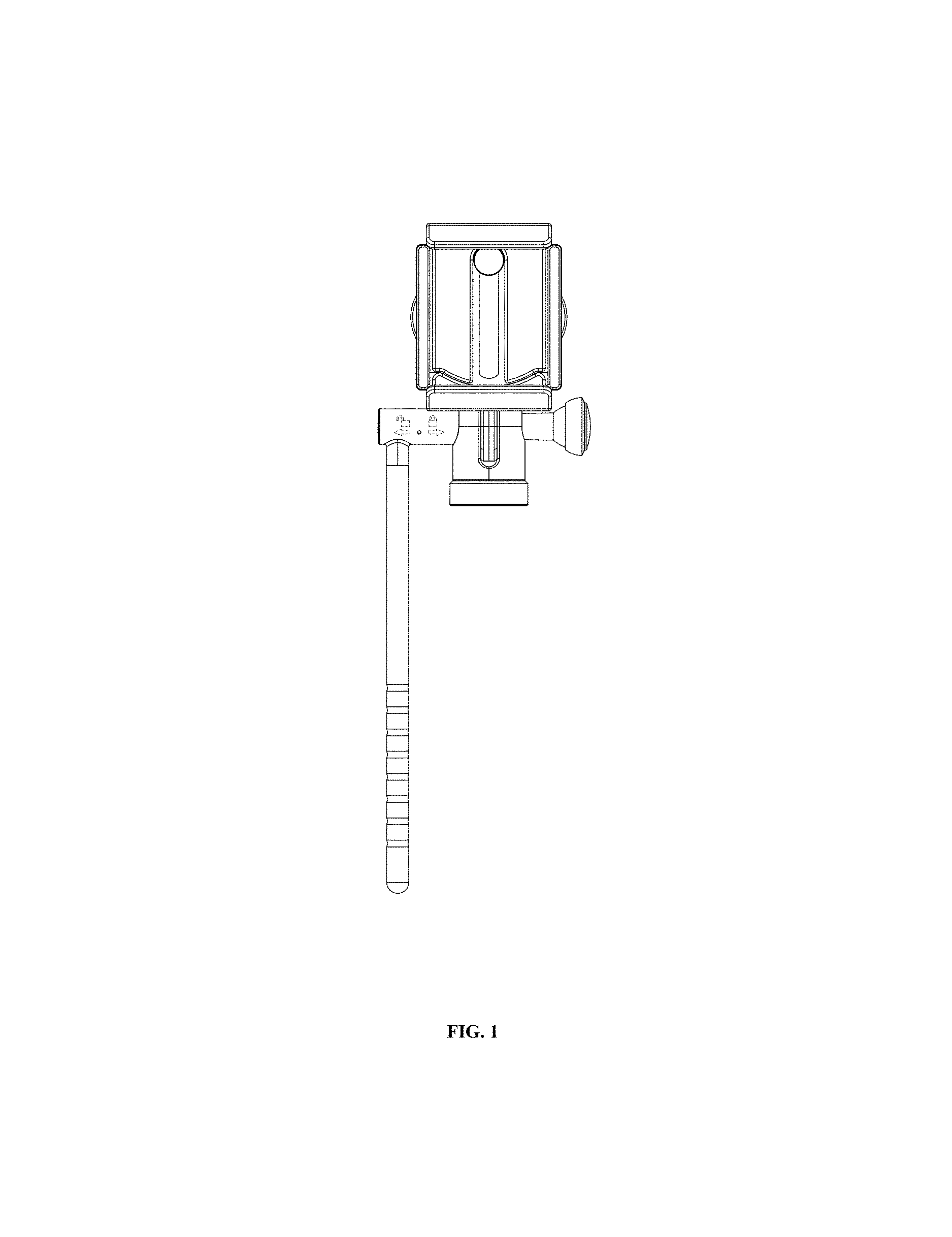
FIG. 1 is a front view of a pan and tilt body with device mounting clamp in a first configuration with the clamp fully closed and the adjustment arm vertically down.
FIG. 2 is a back view of a pan and tilt body with device mounting clamp in a first configuration with the clamp fully closed and the adjustment arm vertically down.
FIG. 3 is a top view of a pan and tilt body with device mounting clamp in a first configuration with the clamp fully closed and the adjustment arm vertically down.
FIG. 4 is a bottom view of a pan and tilt body with device mounting clamp in a first configuration with the clamp fully closed and the adjustment arm vertically down.
FIG. 5 is a left side view of a pan and tilt body with device mounting clamp in a first configuration with the clamp fully closed and the adjustment arm vertically down.
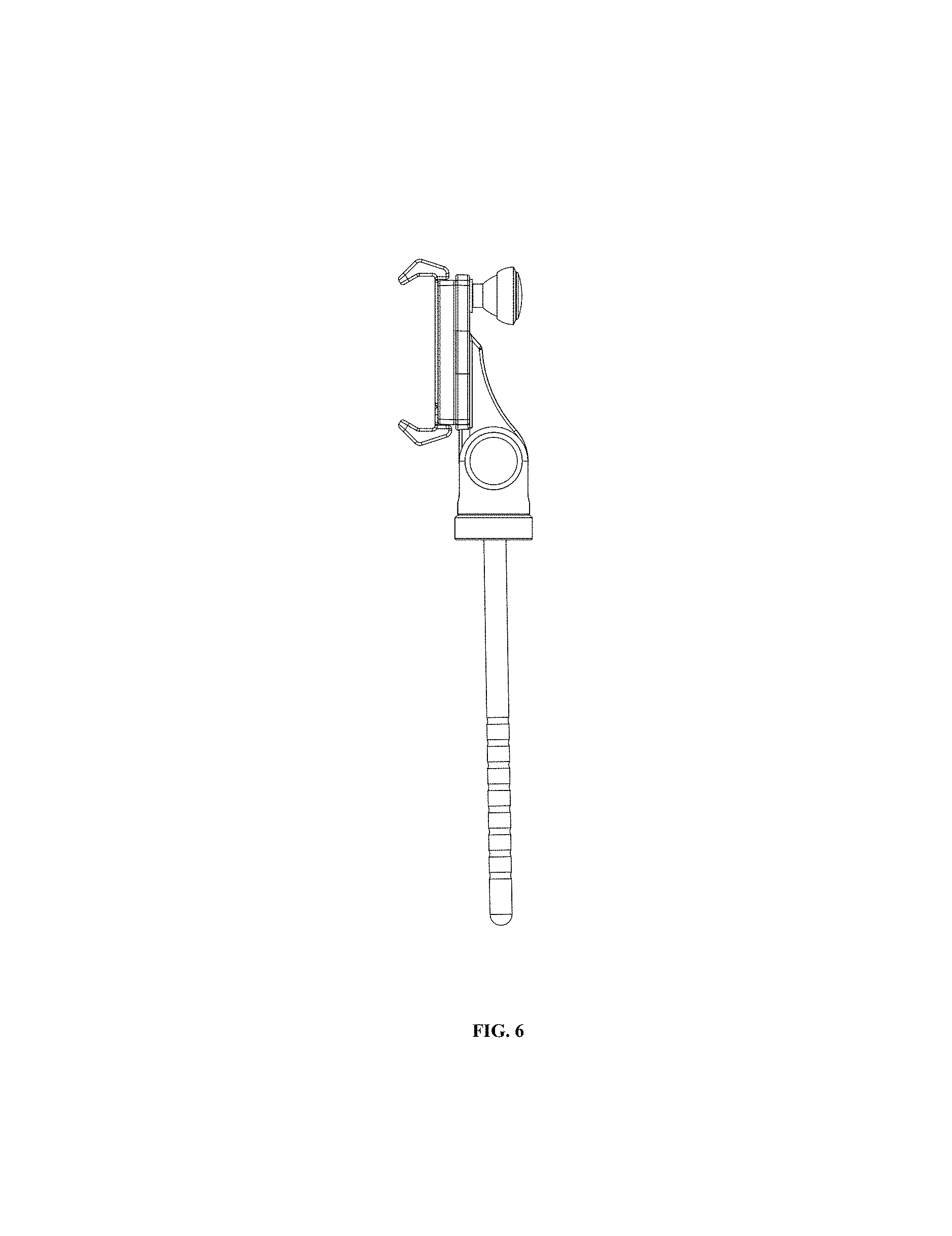
FIG. 6 is a right side view of a pan and tilt body with device mounting clamp in a first configuration with the clamp fully closed and the adjustment arm vertically down.
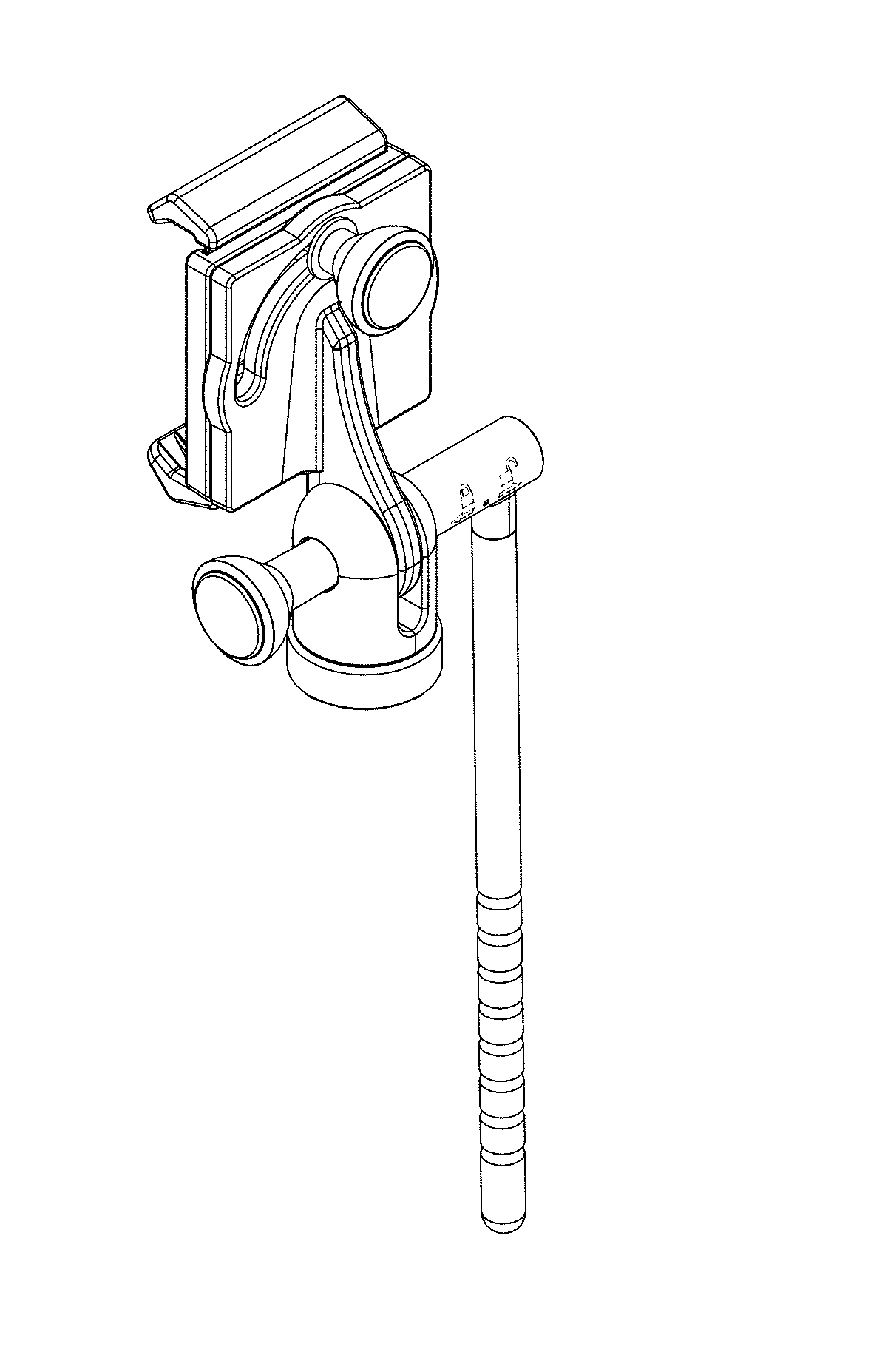
FIG. 7 is a perspective view of a pan and tilt body with device mounting clamp in a first configuration with the clamp fully closed and the adjustment arm vertically down.
FIG. 8 is a front view of a pan and tilt body with device mounting clamp in a second configuration with the clamp fully open and the adjustment arm vertically down.
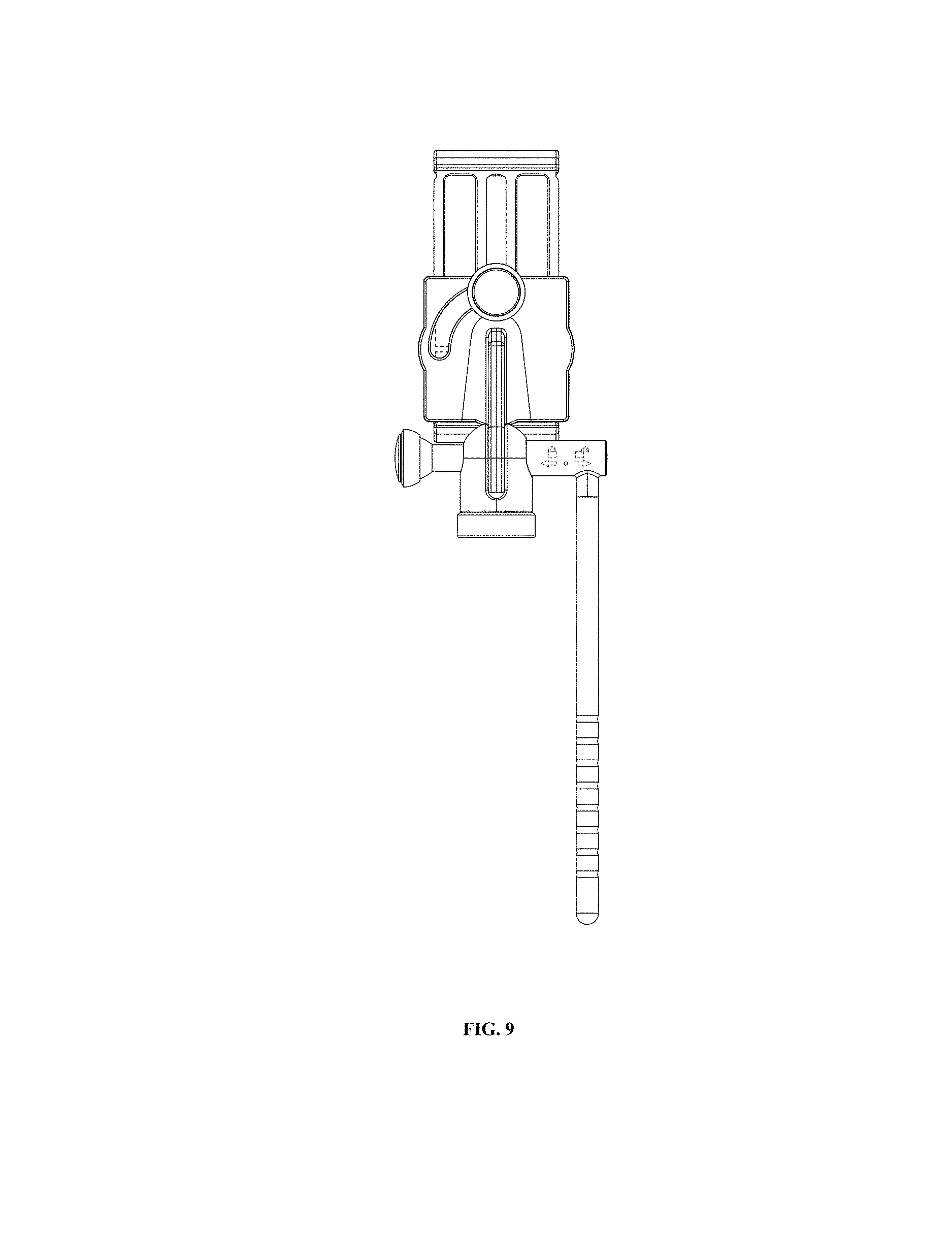
FIG. 9 is a back view of a pan and tilt body with device mounting clamp in a second configuration with the clamp fully open and the adjustment arm vertically down.
FIG. 10 is a left side view of a pan and tilt body with device mounting clamp in a second configuration with the clamp fully open and the adjustment arm vertically down.
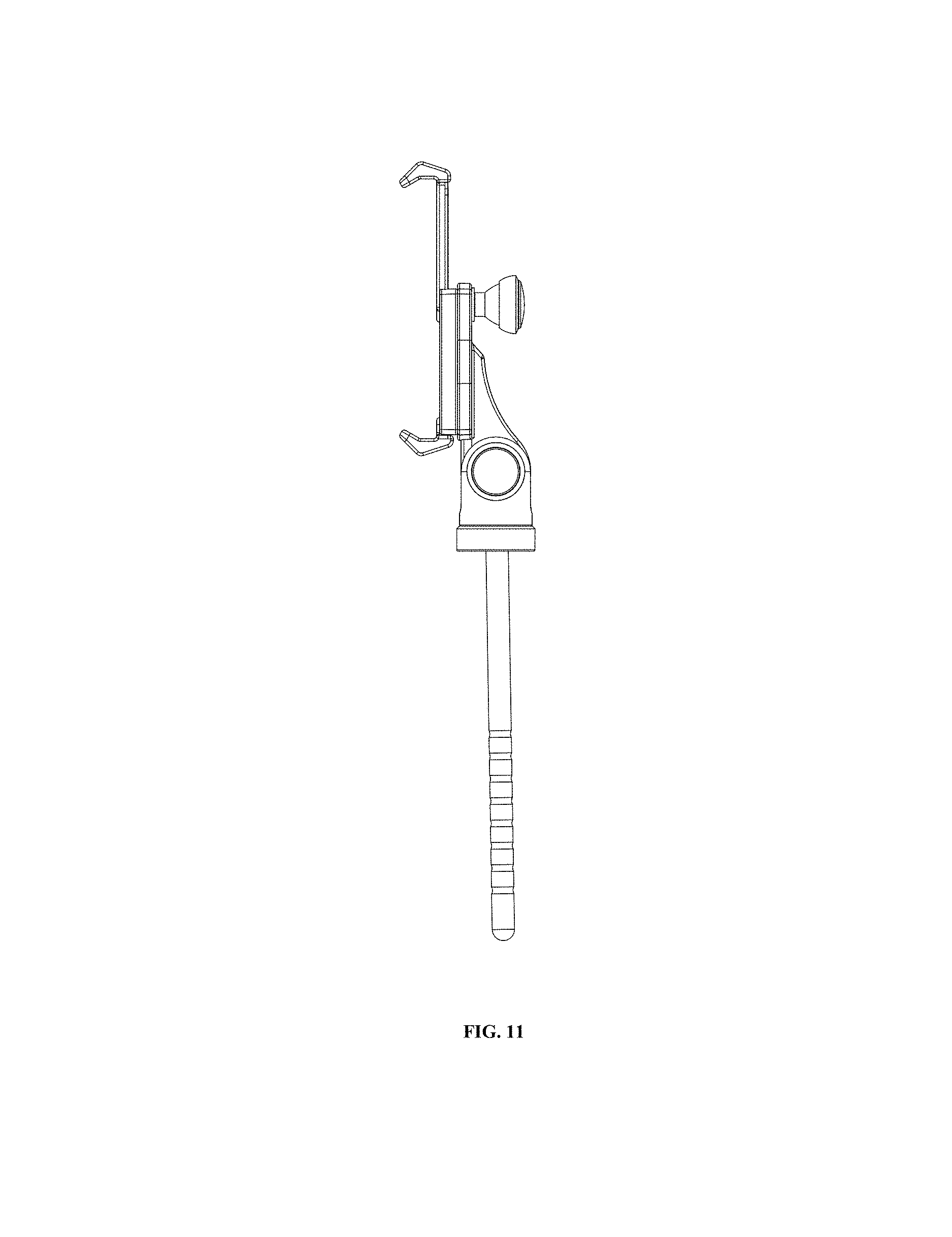
FIG. 11 is a right side view of a pan and tilt body with device mounting clamp in a second configuration with the clamp fully open and the adjustment arm vertically down.
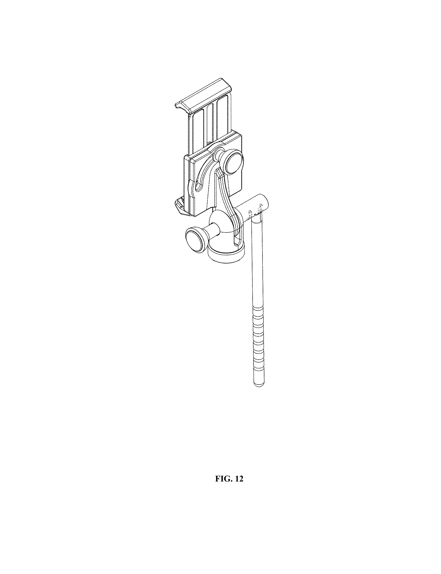
FIG. 12 is a perspective view of a pan and tilt body with device mounting clamp in a second configuration with the clamp fully open and the adjustment arm vertically down.
FIG. 13 is a front view of a pan and tilt body with device mounting clamp in a third configuration with the clamp fully open and the adjustment arm horizontal.
FIG. 14 is a back view of a pan and tilt body with device mounting clamp in a third configuration with the clamp fully open and the adjustment arm horizontal.
FIG. 15 is a left side view of a pan and tilt body with device mounting clamp in a third configuration with the clamp fully open and the adjustment arm horizontal.
FIG. 16 is a right side view of a pan and tilt body with device mounting clamp in a third configuration with the clamp fully open and the adjustment arm horizontal; and,
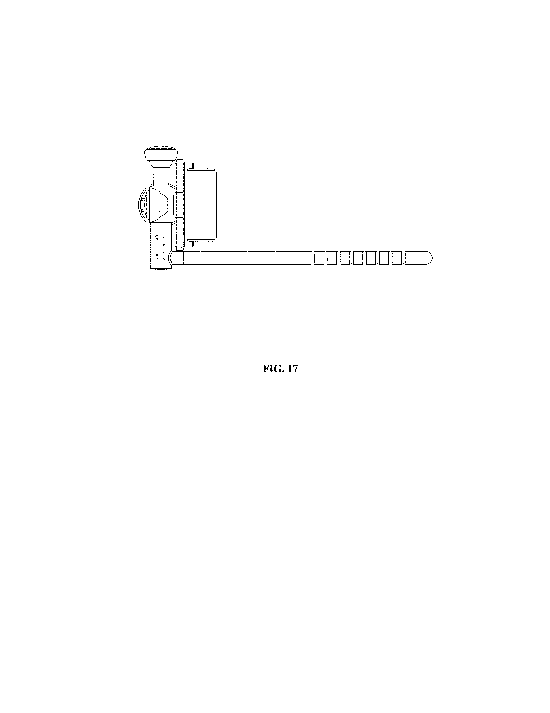
FIG. 17 is a top view of a pan and tilt body with device mounting clamp in a third configuration with the clamp fully open and the adjustment arm horizontal.
The broken lines in the drawing depict portions of the pan and tilt body with device mounting clamp that form no part of the claimed design.
* * * * *
References
D00000
D00001
D00002
D00003
D00004
D00005
D00006
D00007
D00008
D00009
D00010
D00011
D00012

D00013

D00014

D00015

D00016
XML
uspto.report is an independent third-party trademark research tool that is not affiliated, endorsed, or sponsored by the United States Patent and Trademark Office (USPTO) or any other governmental organization. The information provided by uspto.report is based on publicly available data at the time of writing and is intended for informational purposes only.
While we strive to provide accurate and up-to-date information, we do not guarantee the accuracy, completeness, reliability, or suitability of the information displayed on this site. The use of this site is at your own risk. Any reliance you place on such information is therefore strictly at your own risk.
All official trademark data, including owner information, should be verified by visiting the official USPTO website at www.uspto.gov. This site is not intended to replace professional legal advice and should not be used as a substitute for consulting with a legal professional who is knowledgeable about trademark law.