HVAC control device
Thoren , et al.
U.S. patent number D843,236 [Application Number D/608,990] was granted by the patent office on 2019-03-19 for hvac control device. This patent grant is currently assigned to DAIKIN MANUFACTURING COMPANY, L.P.. The grantee listed for this patent is Daikin Manufacturing Company, L.P.. Invention is credited to Chris Bellshaw, Shawn Beus, Fred Bould, Jacky Chen, Kelly Hearnsberger, Ryohei Hinokuma, Tao Jia, Byron Lee, Jamie S. Perin, Dennis Thoren, Jeremy Wolf.

| United States Patent | D843,236 |
| Thoren , et al. | March 19, 2019 |
HVAC control device
Claims
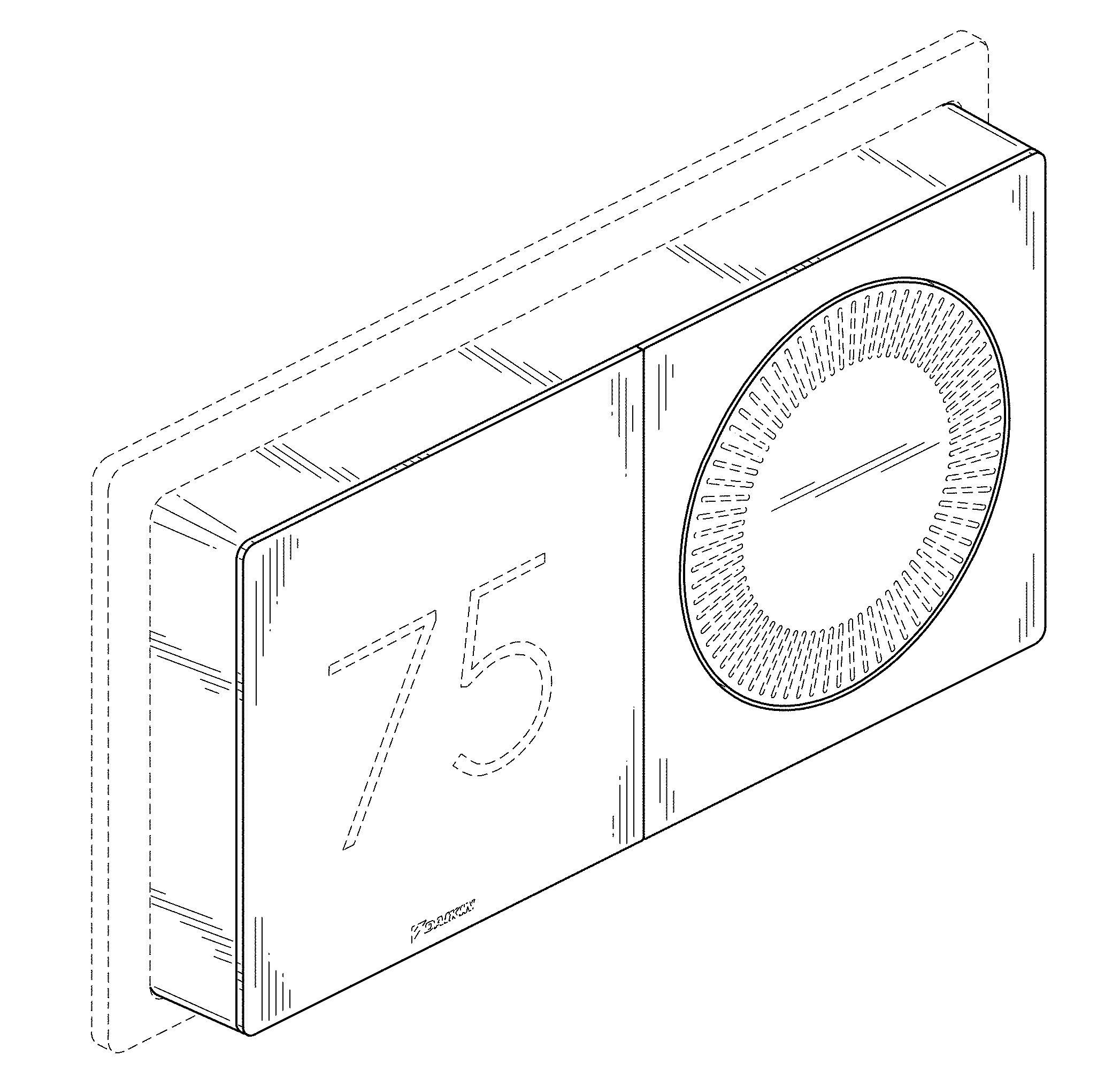
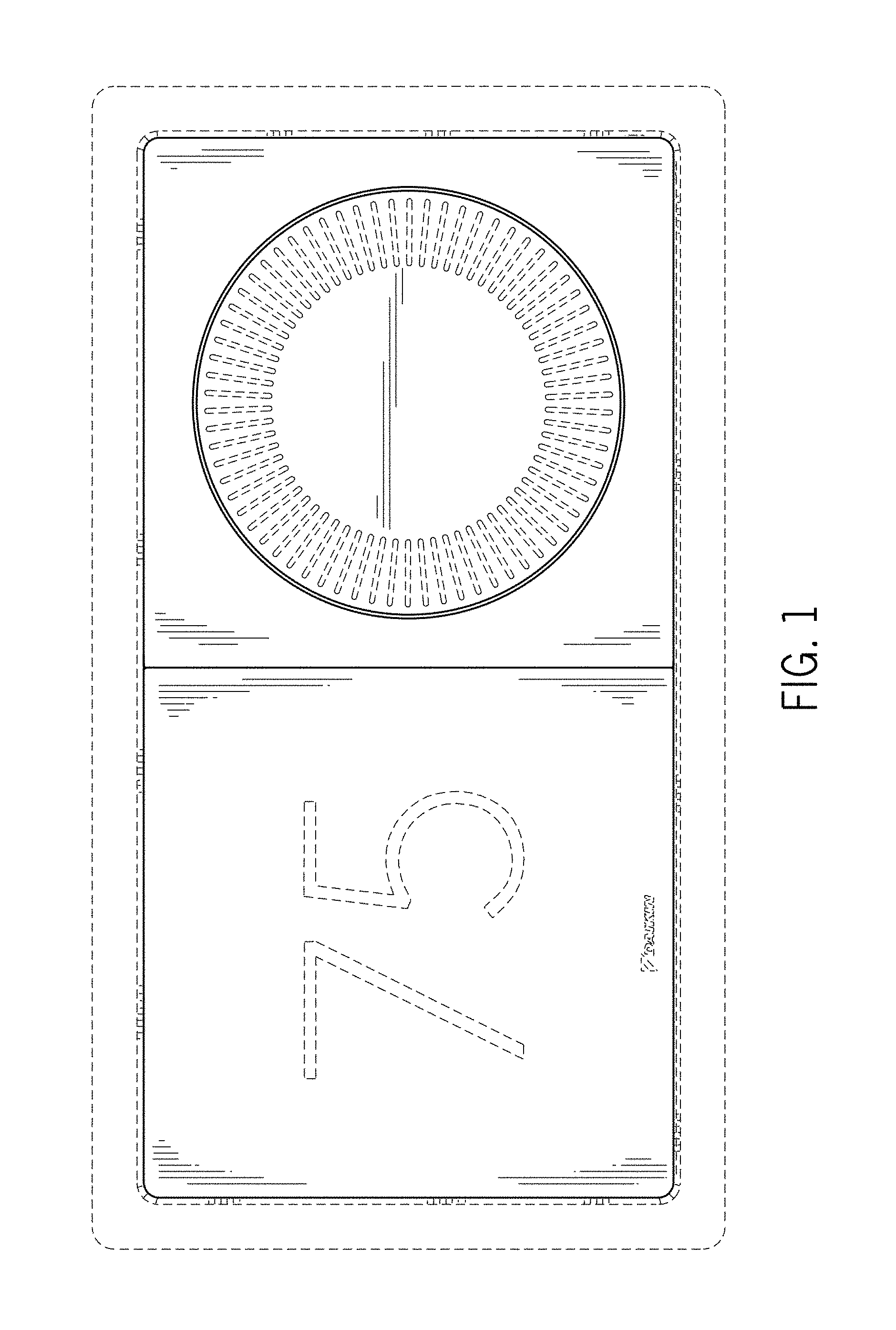
CLAIM The ornamental design for an HVAC control device, as shown and described.
| Inventors: | Thoren; Dennis (Lindale, TX), Jia; Tao (Moorseville, NC), Chen; Jacky (Katy, TX), Bellshaw; Chris (Houston, TX), Beus; Shawn (Houston, TX), Hearnsberger; Kelly (Katy, TX), Hinokuma; Ryohei (Foster City, CA), Bould; Fred (Menlo Park, CA), Wolf; Jeremy (San Francisco, CA), Lee; Byron (San Mateo, CA), Perin; Jamie S. (San Francisco, CA) | ||||||||||
|---|---|---|---|---|---|---|---|---|---|---|---|
| Applicant: |
|
||||||||||
| Assignee: | DAIKIN MANUFACTURING COMPANY,
L.P. (Houston, TX) |
||||||||||
| Appl. No.: | D/608,990 | ||||||||||
| Filed: | June 27, 2017 |
| Current U.S. Class: | D10/50; D10/60; D13/177; D13/162.1 |
| Current International Class: | 1004 |
| Field of Search: | ;D10/49,50,60,102,103 ;D13/162,162.1,177 |
References Cited [Referenced By]
U.S. Patent Documents
| D251482 | April 1979 | Sugiyama |
| D270815 | October 1983 | Odom |
| D614976 | May 2010 | Skafdrup |
| D723948 | March 2015 | Baumgartner |
| D772735 | November 2016 | Mansueto |
| 2017/0082313 | March 2017 | Benichou |
Attorney, Agent or Firm: Vyas; Manish
Description
FIG. 1 is a front view of an HVAC control device showing the new design;
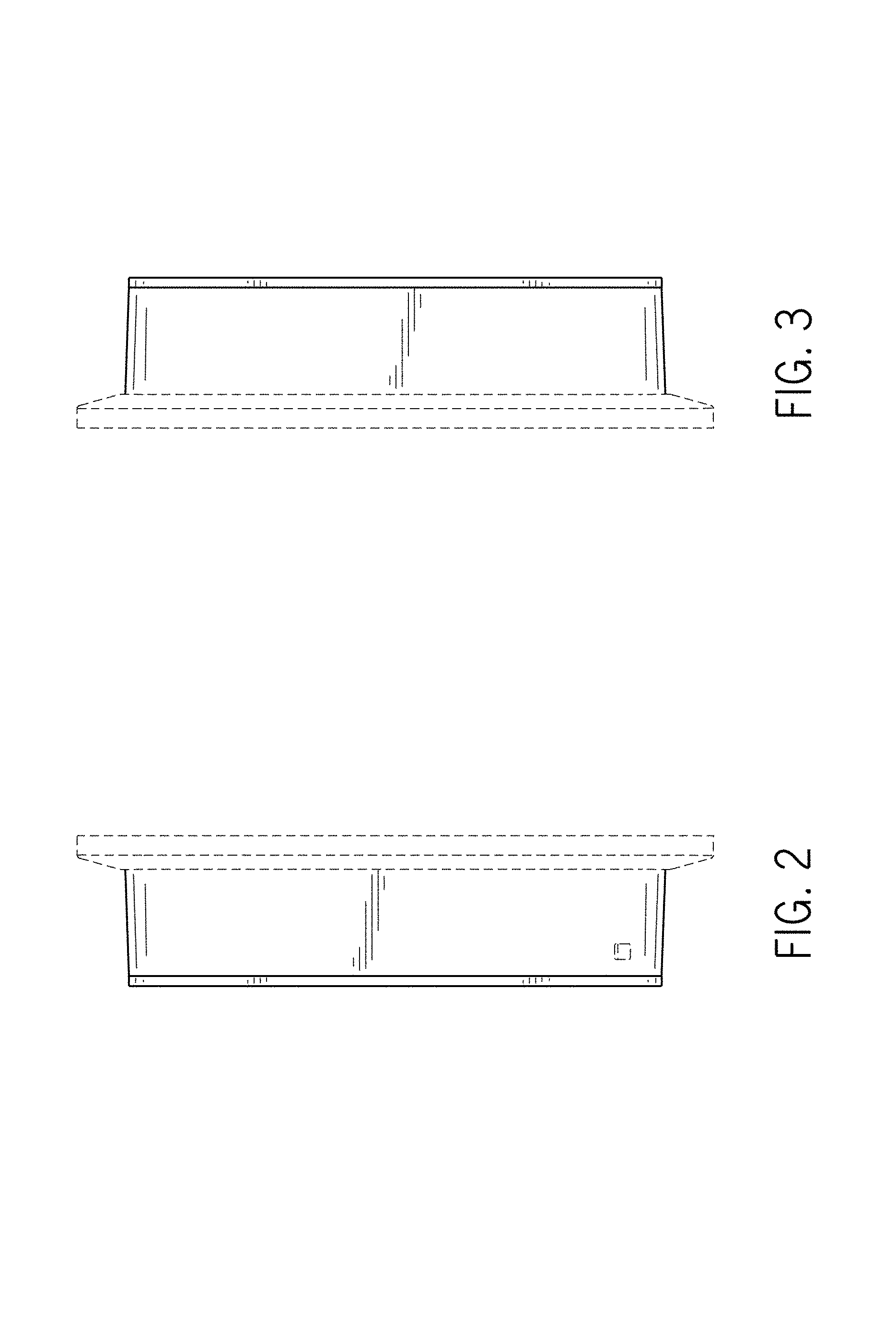
FIG. 2 is a right side view thereof;
FIG. 3 is a left side view thereof;
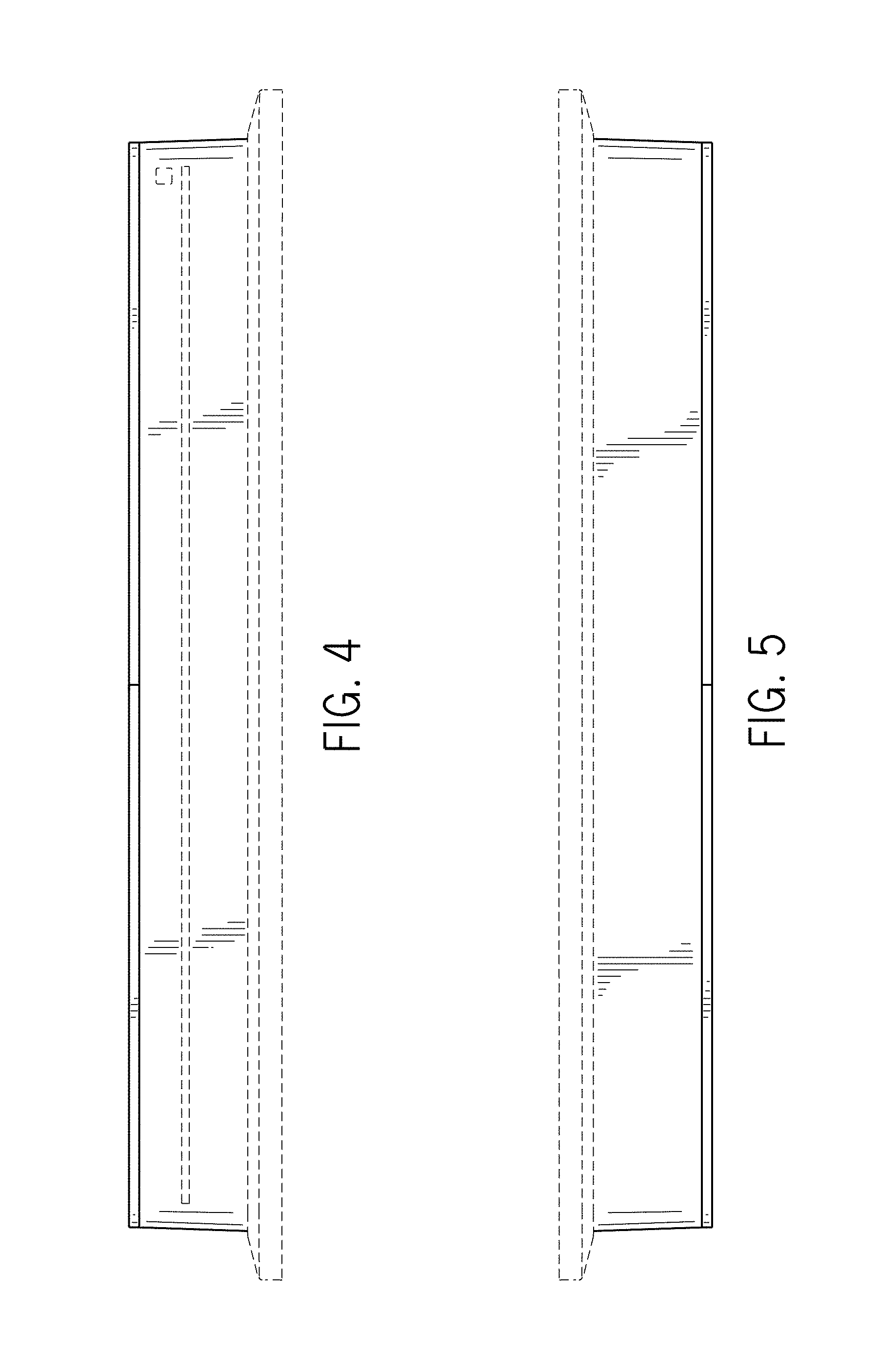
FIG. 4 is a bottom view thereof;
FIG. 5 is a top view thereof;
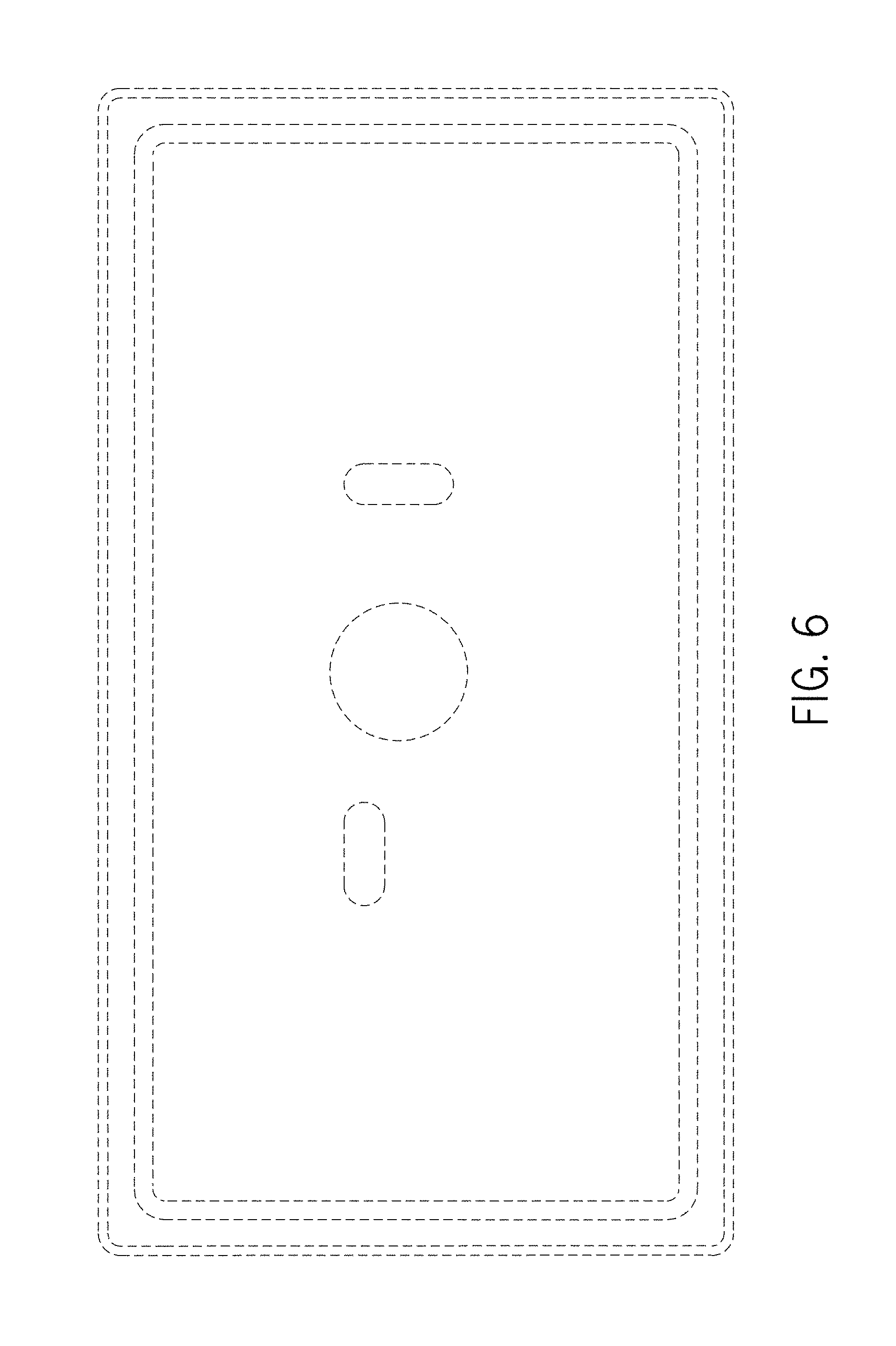
FIG. 6 is a rear view thereof;
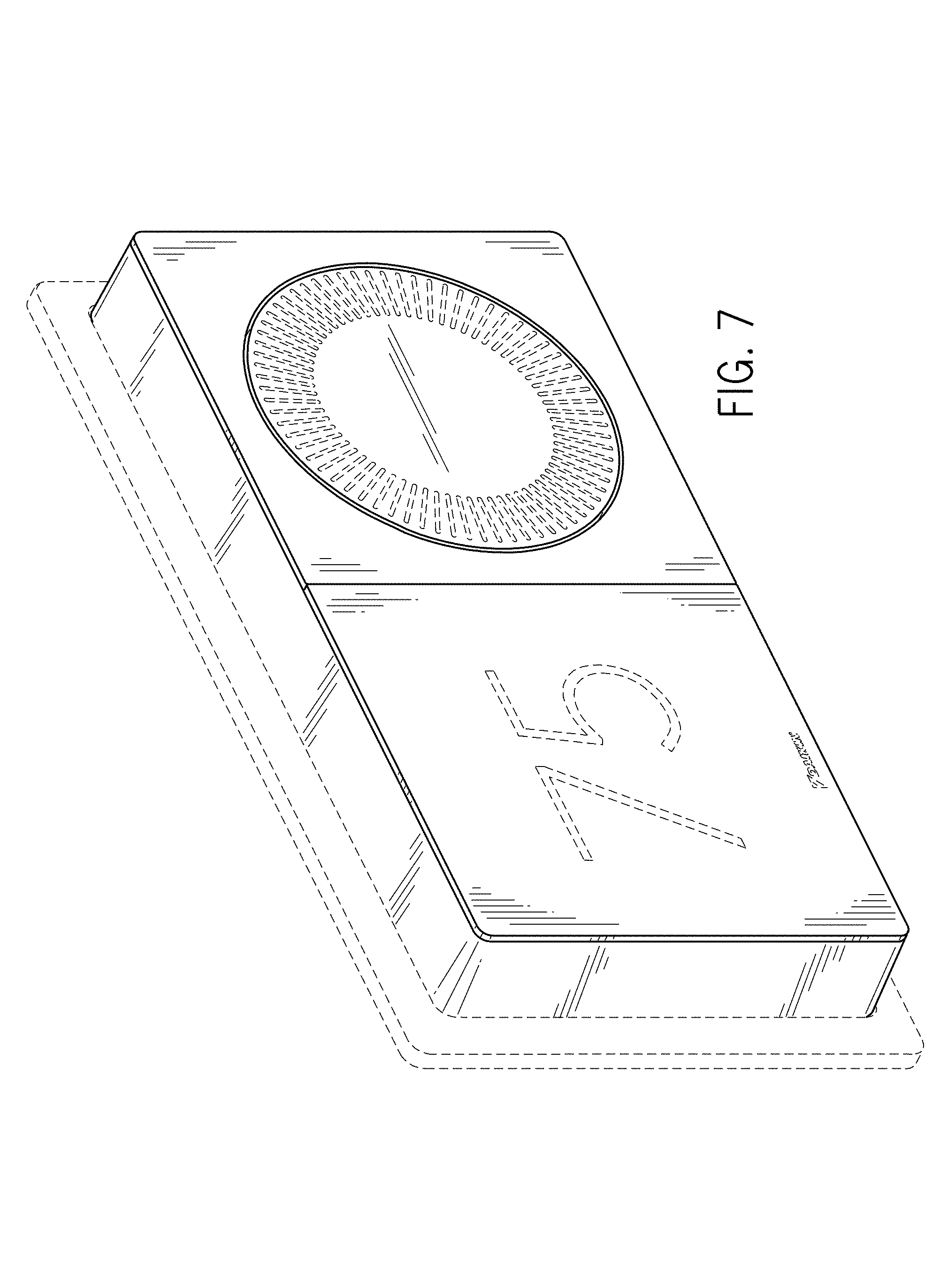
FIG. 7 is a front perspective view thereof;
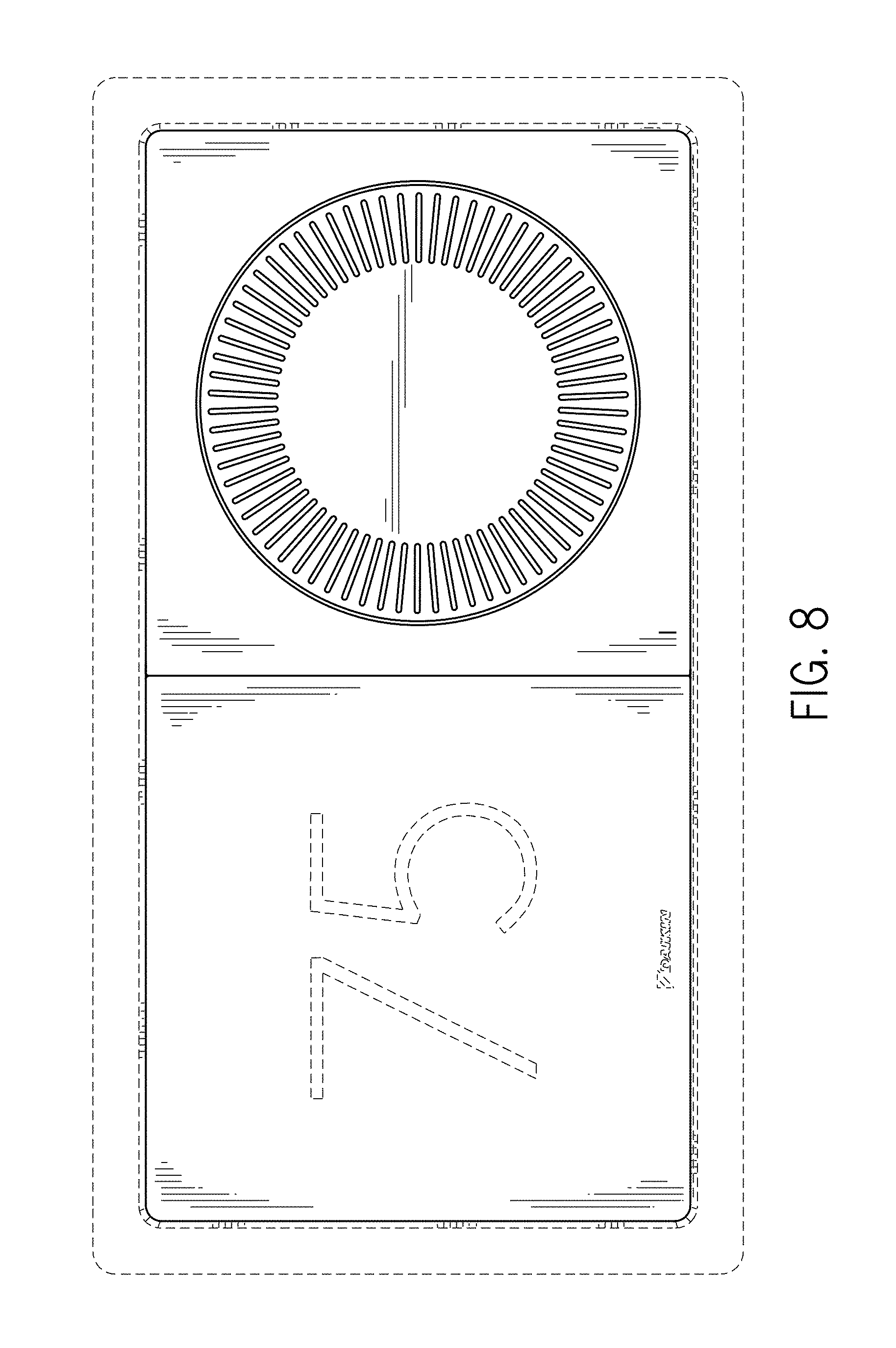
FIG. 8 is a front view of an HVAC control device showing a second embodiment of the new design; and,
FIG. 9 is a front perspective view thereof.
The dashed broken lines represent structures, features or the environment that form no part of the claimed design.
* * * * *
D00000
D00001
D00002
D00003
D00004
D00005
D00006
D00007
XML
uspto.report is an independent third-party trademark research tool that is not affiliated, endorsed, or sponsored by the United States Patent and Trademark Office (USPTO) or any other governmental organization. The information provided by uspto.report is based on publicly available data at the time of writing and is intended for informational purposes only.
While we strive to provide accurate and up-to-date information, we do not guarantee the accuracy, completeness, reliability, or suitability of the information displayed on this site. The use of this site is at your own risk. Any reliance you place on such information is therefore strictly at your own risk.
All official trademark data, including owner information, should be verified by visiting the official USPTO website at www.uspto.gov. This site is not intended to replace professional legal advice and should not be used as a substitute for consulting with a legal professional who is knowledgeable about trademark law.