Medical tube holder
Wakabayashi , et al. Feb
U.S. patent number D841,802 [Application Number D/609,320] was granted by the patent office on 2019-02-26 for medical tube holder. This patent grant is currently assigned to ATOM MEDICAL CORPORATION. The grantee listed for this patent is ATOM MEDICAL CORPORATION. Invention is credited to Yoshiyuki Komiyama, Ichiro Matsubara, Masaaki Oohashi, Keisuke Wakabayashi.


View All Diagrams
| United States Patent | D841,802 |
| Wakabayashi , et al. | February 26, 2019 |
Medical tube holder
Claims
CLAIM We claim the ornamental design for a medical tube holder, as shown and described.
| Inventors: | Wakabayashi; Keisuke (Saitama, JP), Oohashi; Masaaki (Saitama, JP), Komiyama; Yoshiyuki (Saitama, JP), Matsubara; Ichiro (Tokyo, JP) | ||||||||||
|---|---|---|---|---|---|---|---|---|---|---|---|
| Applicant: |
|
||||||||||
| Assignee: | ATOM MEDICAL CORPORATION
(Tokyo, JP) |
||||||||||
| Appl. No.: | D/609,320 | ||||||||||
| Filed: | June 29, 2017 |
Foreign Application Priority Data
| Jan 12, 2017 [JP] | 2017-000332 | |||
| Current U.S. Class: | D24/128 |
| Current International Class: | 2402 |
| Field of Search: | ;D24/127-131,112-114,133,186 ;606/181,185 ;604/264,523-528,272,187,158,164.01-164.11,181,184,227 ;600/101,139,143 ;128/200.24,207.14,207.15 ;D8/396 |
References Cited [Referenced By]
U.S. Patent Documents
| D291728 | September 1987 | Hoyt |
| D322735 | December 1991 | Morton |
| D376974 | December 1996 | Chen |
| D389052 | January 1998 | Yamamoto |
| D389733 | January 1998 | Nakamura |
| 6405414 | June 2002 | Byrnes |
| D484592 | December 2003 | Ryhman |
| D536607 | February 2007 | Bekkevold |
| D695100 | December 2013 | Whitaker |
| D761643 | July 2016 | Papafagos |
| D780860 | March 2017 | Jones |
| D804942 | December 2017 | Toll |
| D808256 | January 2018 | Muller |
| 2013/0174838 | July 2013 | Youngblood |
| 2013-56114 | Mar 2013 | JP | |||
Attorney, Agent or Firm: Brinks Gilson & Lione
Description
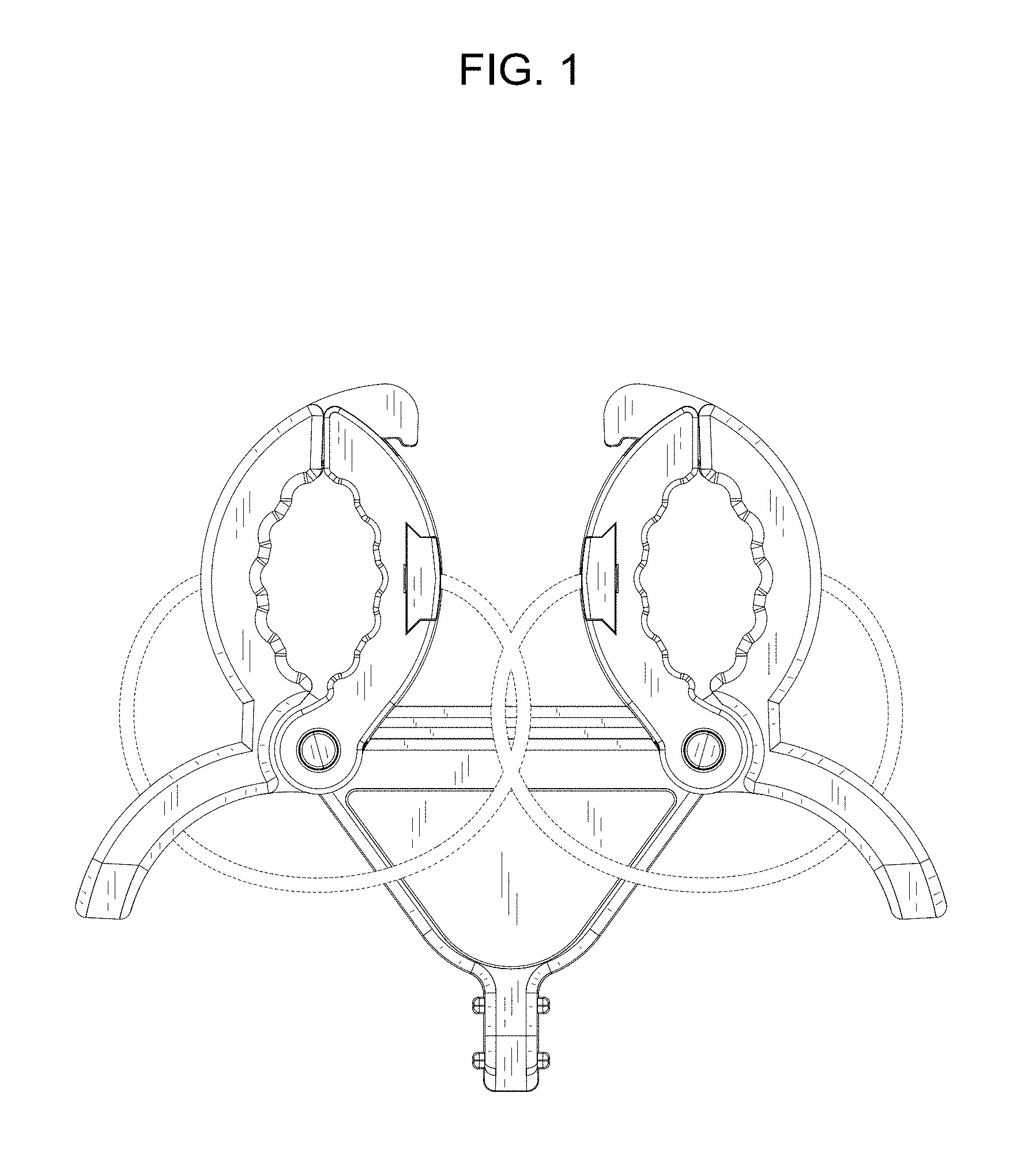
FIG. 1 is a front view of a medical tube holder of the present invention, with two pairs of claws shown in a closed position;
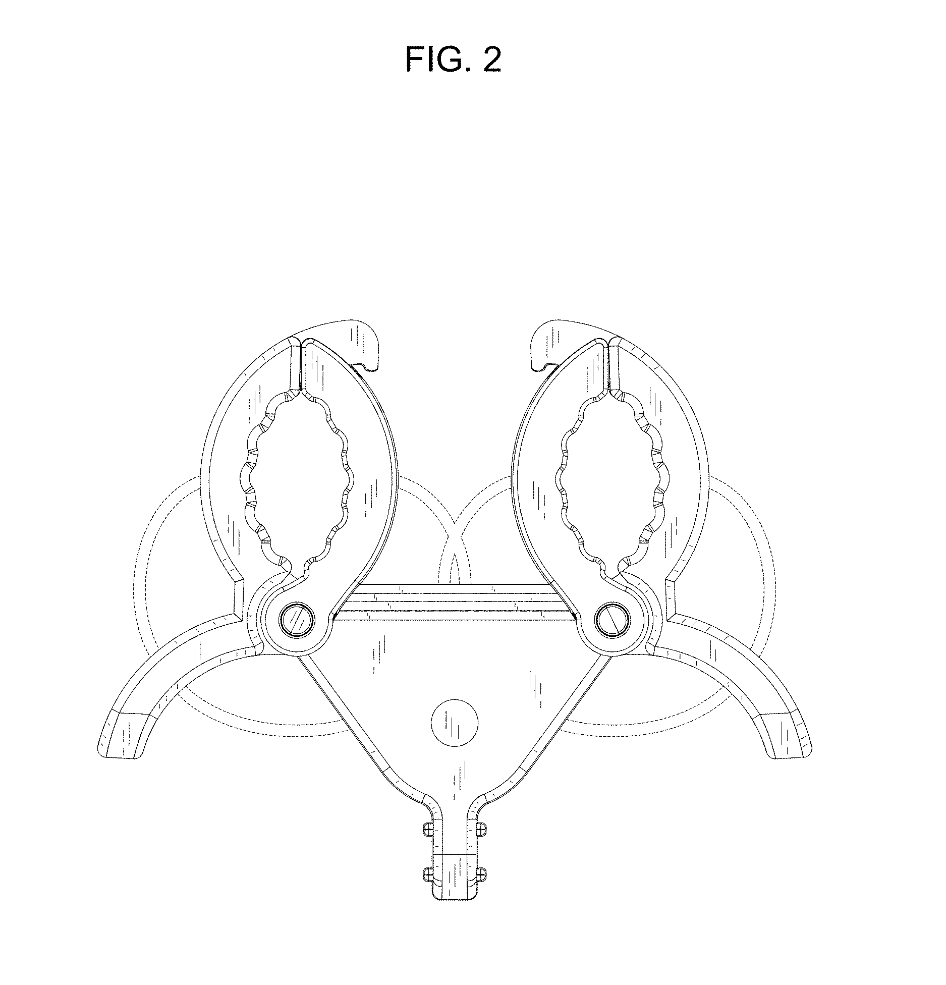
FIG. 2 is a rear view thereof;
FIG. 3 is a plain view thereof;
FIG. 4 is a bottom view thereof;
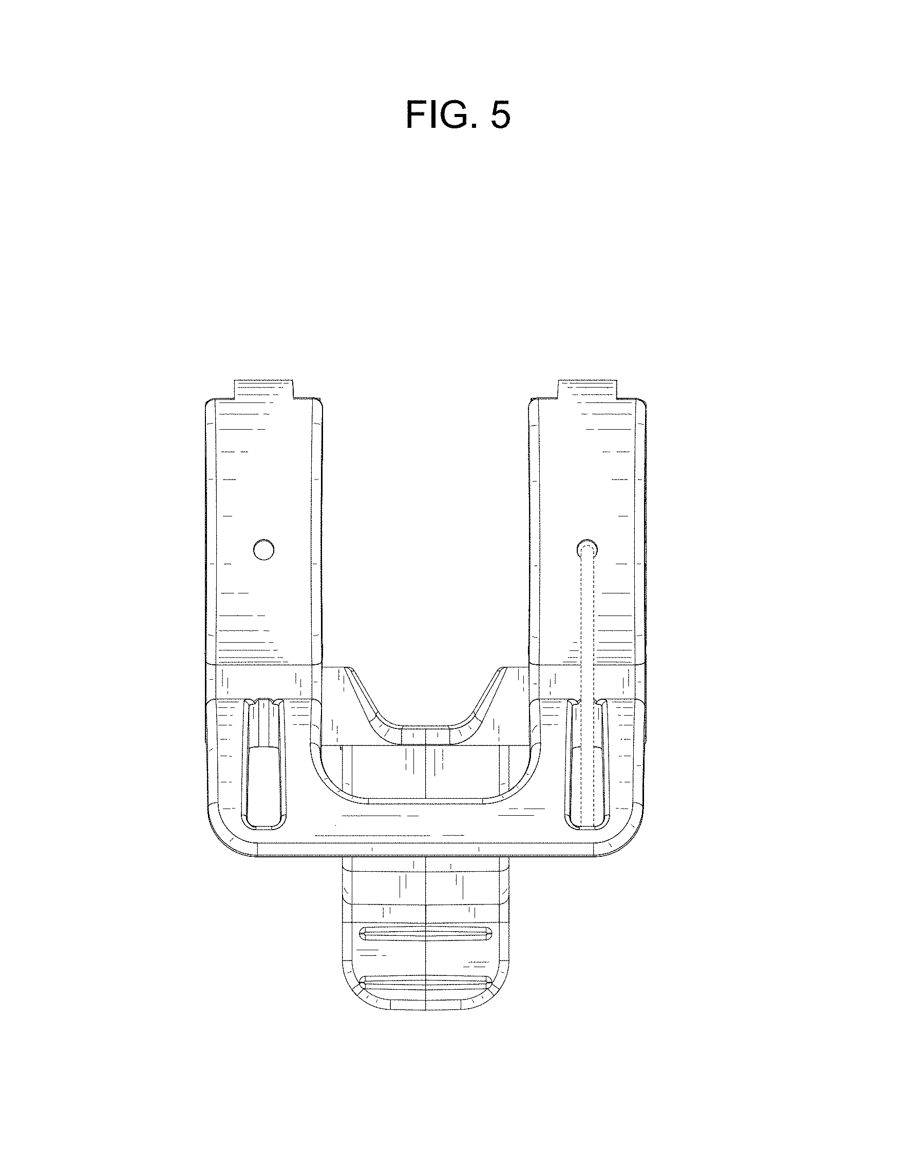
FIG. 5 is a left side view thereof;
FIG. 6 is a right side view thereof;
FIG. 7 is a perspective view thereof;
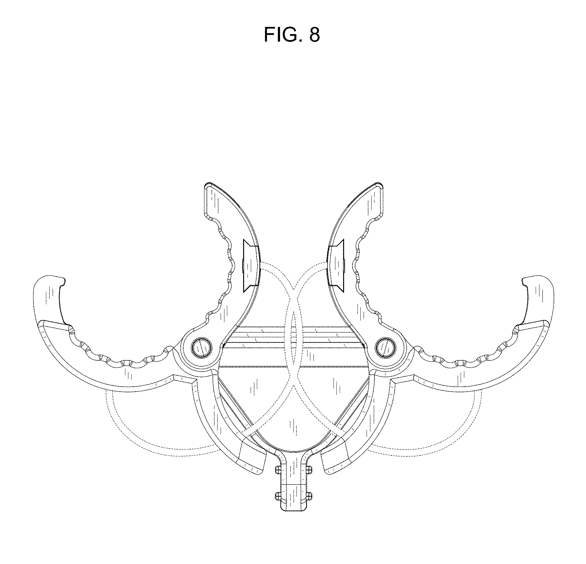
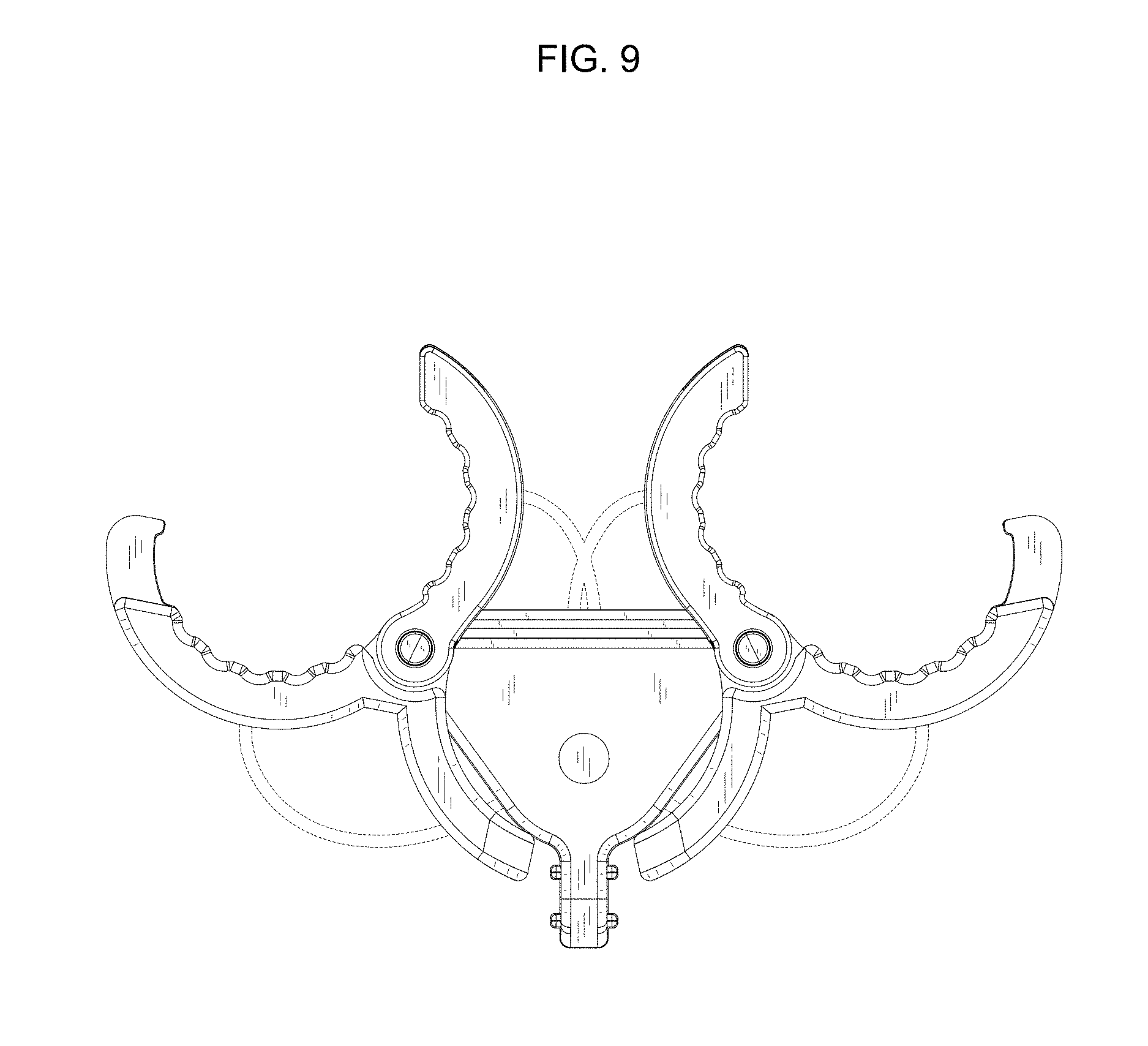
FIG. 8 is a front view of the medical tube holder of the present invention, with the two pairs of claws shown in an open position;
FIG. 9 is a rear view thereof;
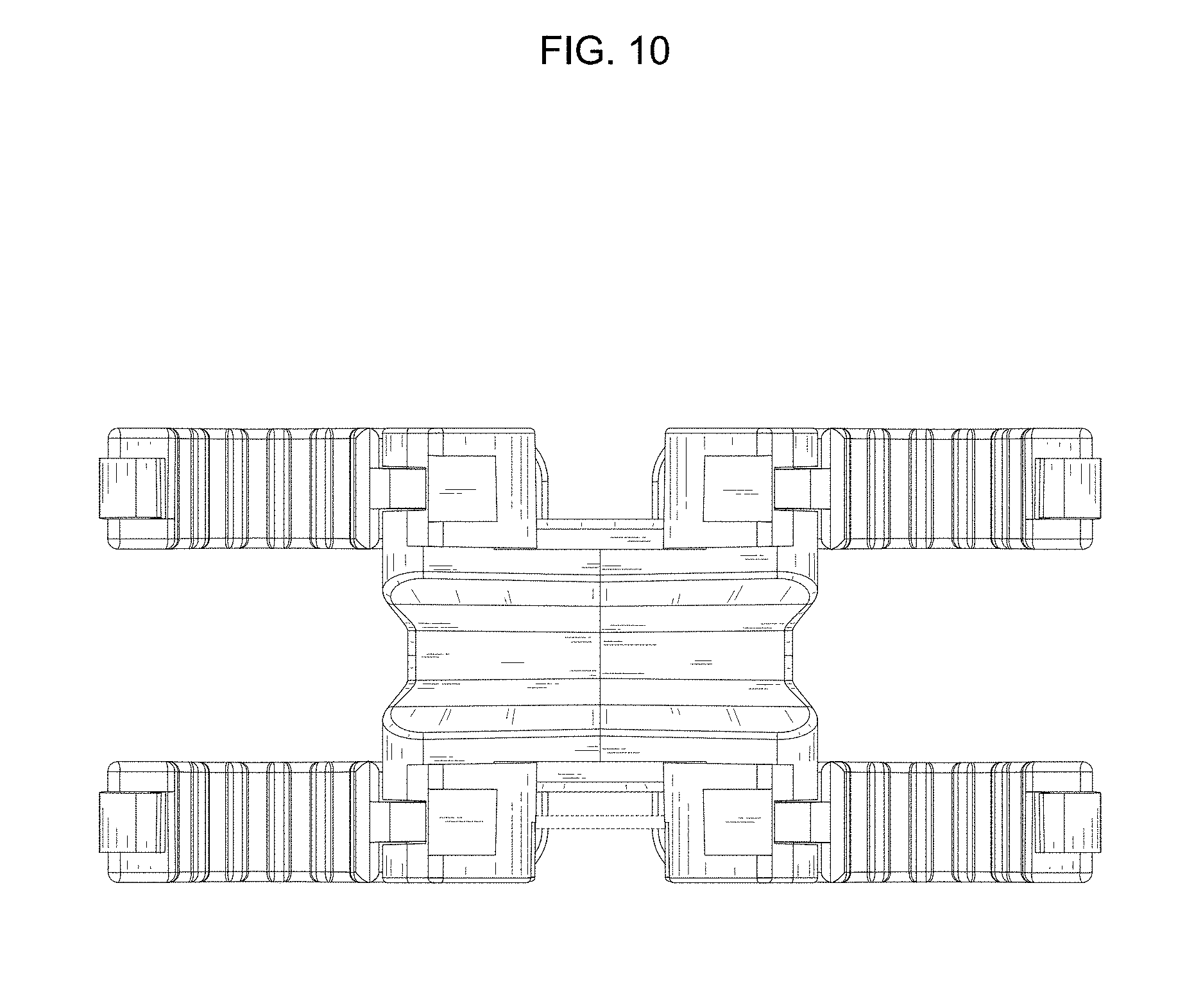
FIG. 10 is a plain view thereof;
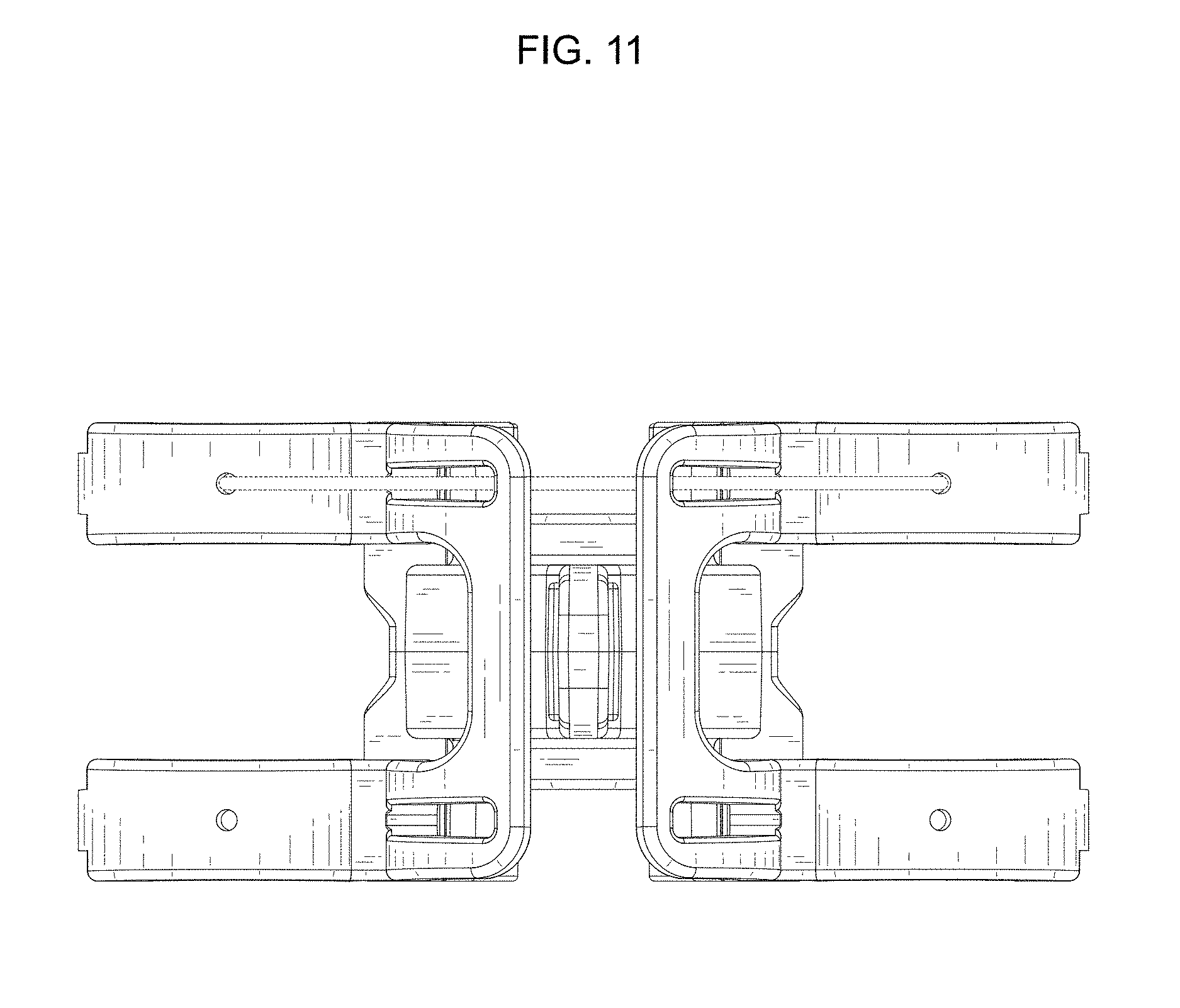
FIG. 11 is a bottom view thereof;
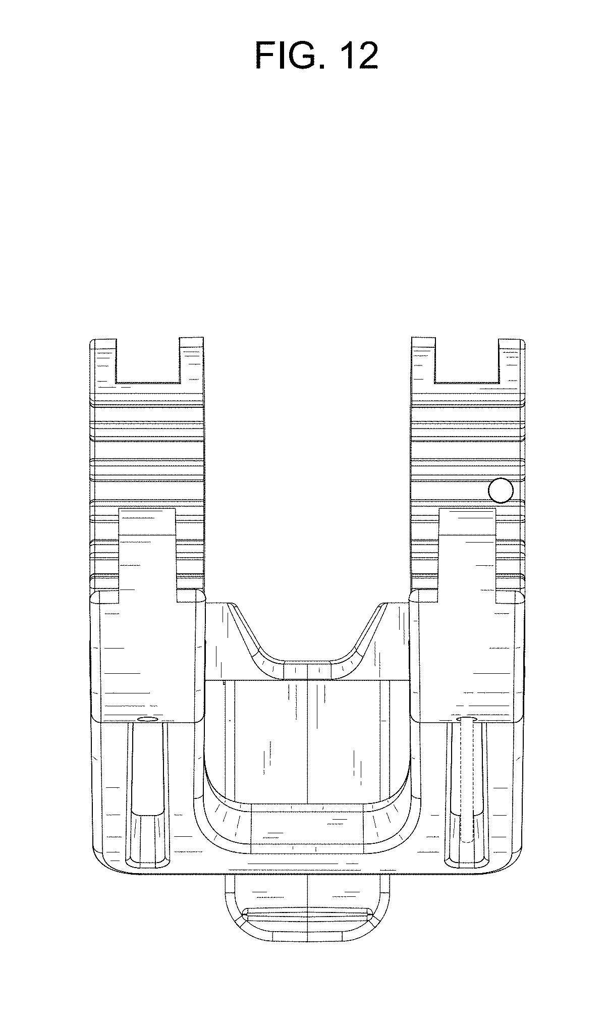
FIG. 12 is a left side view thereof;
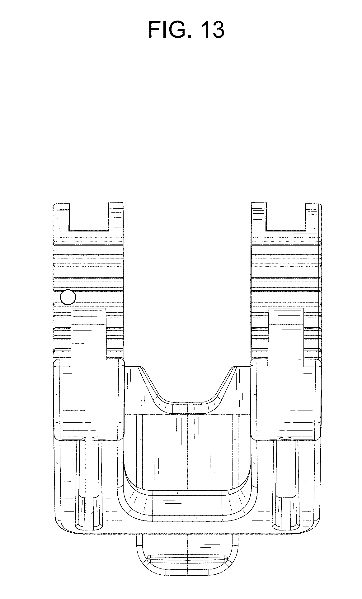
FIG. 13 is a right side view thereof; and,
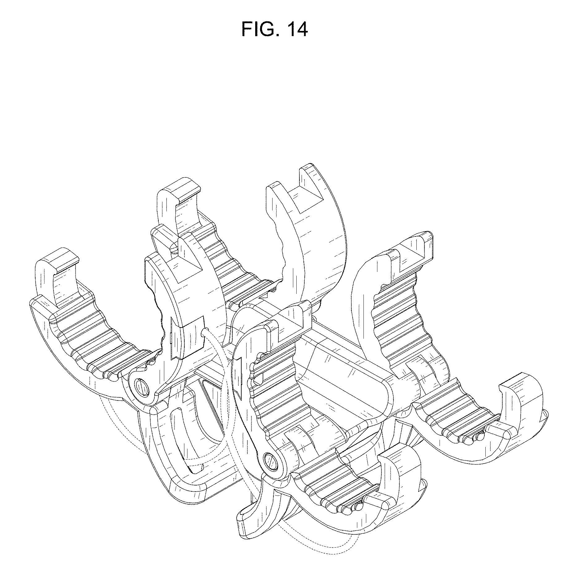
FIG. 14 is a perspective view thereof.
The broken line showing of parts of the drawings is included for the purpose of illustrating use and environment and forms no part of the claimed design.
* * * * *
D00000
D00001
D00002
D00003
D00004
D00005
D00006
D00007
D00008
D00009
D00010
D00011
D00012
D00013
D00014
XML
uspto.report is an independent third-party trademark research tool that is not affiliated, endorsed, or sponsored by the United States Patent and Trademark Office (USPTO) or any other governmental organization. The information provided by uspto.report is based on publicly available data at the time of writing and is intended for informational purposes only.
While we strive to provide accurate and up-to-date information, we do not guarantee the accuracy, completeness, reliability, or suitability of the information displayed on this site. The use of this site is at your own risk. Any reliance you place on such information is therefore strictly at your own risk.
All official trademark data, including owner information, should be verified by visiting the official USPTO website at www.uspto.gov. This site is not intended to replace professional legal advice and should not be used as a substitute for consulting with a legal professional who is knowledgeable about trademark law.