Camera mount
Bergman , et al. Feb
U.S. patent number D841,722 [Application Number D/607,455] was granted by the patent office on 2019-02-26 for camera mount. This patent grant is currently assigned to GoPro, Inc.. The grantee listed for this patent is GoPro, Inc.. Invention is credited to Eric Mccallister Bennett, Senka Agic Bergman, Joshua T. Druker, Arthur Charles Kwun, Huy Phuong Nguyen, Travis Pynn, Nicholas D. Woodman.


| United States Patent | D841,722 |
| Bergman , et al. | February 26, 2019 |
Camera mount
Claims
CLAIM The ornamental design for a camera mount, as shown and described.
| Inventors: | Bergman; Senka Agic (Montara, CA), Kwun; Arthur Charles (Newark, CA), Nguyen; Huy Phuong (San Mateo, CA), Bennett; Eric Mccallister (Foster City, CA), Woodman; Nicholas D. (Woodside, CA), Druker; Joshua T. (Redwood City, CA), Pynn; Travis (Moss Beach, CA) | ||||||||||
|---|---|---|---|---|---|---|---|---|---|---|---|
| Applicant: |
|
||||||||||
| Assignee: | GoPro, Inc. (San Mateo,
CA) |
||||||||||
| Appl. No.: | D/607,455 | ||||||||||
| Filed: | June 13, 2017 |
| Current U.S. Class: | D16/242 |
| Current International Class: | 1605 |
| Field of Search: | ;D16/219,237-250 ;D14/224,229,238,251,447,451,457 ;D8/354,355,363,373,382,383,394,395,396 |
References Cited [Referenced By]
U.S. Patent Documents
| D713531 | September 2014 | Way |
| D719266 | December 2014 | Goldstein |
| 9426341 | August 2016 | Baldrige |
| D776745 | January 2017 | Bennett et al. |
| D776746 | January 2017 | Bennett et al. |
| D780249 | February 2017 | Ramsthaler |
| 9715164 | July 2017 | Russell |
| 2015/0076184 | March 2015 | Achenbach |
| 2015/0253651 | September 2015 | Russell |
| 2015/0309396 | October 2015 | Rohrer |
| 2015/0316205 | November 2015 | Bennett et al. |
Other References
|
GoPro Bite Mount & Floaty . [online] Published on Oct. 4, 2017. Retrieved Apr. 24, 2018 from URL: https://shop.gopro.com/mounts/bite-mount-plus-floaty/ASLBM-001.html. cited by examiner. |
Primary Examiner: Koenig; Vy N
Attorney, Agent or Firm: Young Basile Hanlon & MacFarlane, P.C.
Description
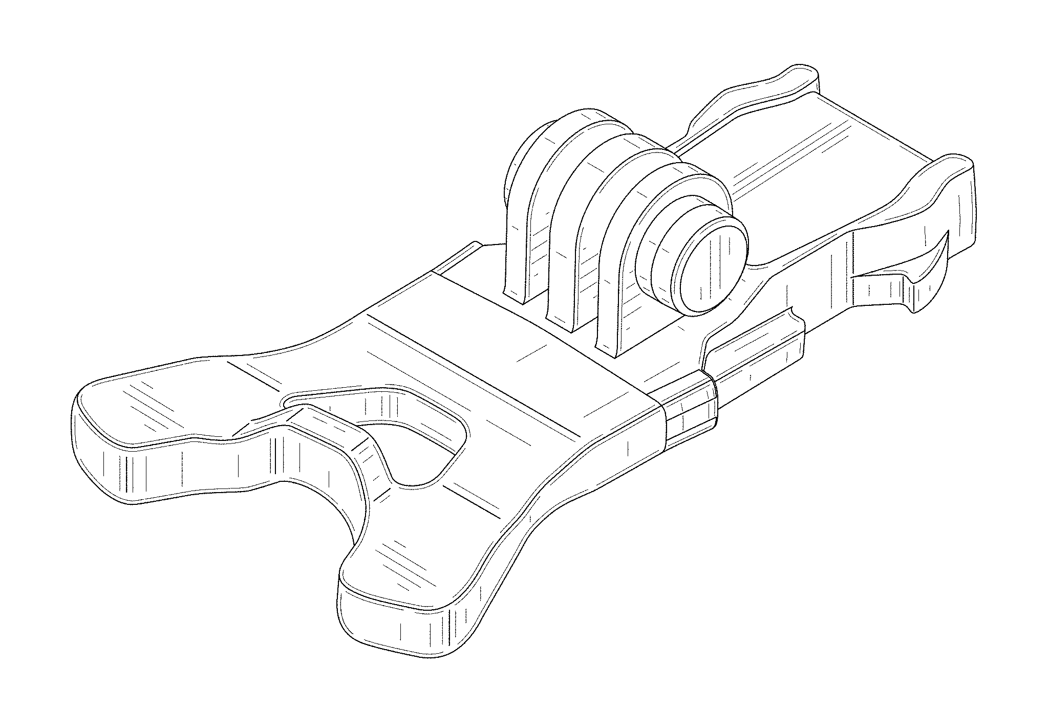
FIG. 1 is a top, rear, left perspective view of a camera mount.
FIG. 2 is a top plan view of the camera mount shown in FIG. 1.
FIG. 3 is a left elevation view of the camera mount shown in FIG. 1.
FIG. 4 is a right elevation view of the camera mount shown in FIG. 1.
FIG. 5 is a rear elevation view of the camera mount shown in FIG. 1; and,
FIG. 6 is a front elevation view of the camera mount shown in FIG. 1.
Broken lines in the drawings represent unclaimed subject matter and form no part of the claimed design.
* * * * *
References
D00000
D00001
D00002
D00003
D00004
D00005
D00006
XML
uspto.report is an independent third-party trademark research tool that is not affiliated, endorsed, or sponsored by the United States Patent and Trademark Office (USPTO) or any other governmental organization. The information provided by uspto.report is based on publicly available data at the time of writing and is intended for informational purposes only.
While we strive to provide accurate and up-to-date information, we do not guarantee the accuracy, completeness, reliability, or suitability of the information displayed on this site. The use of this site is at your own risk. Any reliance you place on such information is therefore strictly at your own risk.
All official trademark data, including owner information, should be verified by visiting the official USPTO website at www.uspto.gov. This site is not intended to replace professional legal advice and should not be used as a substitute for consulting with a legal professional who is knowledgeable about trademark law.