Casing for a measuring instrument
Guhr Feb
U.S. patent number D841,488 [Application Number D/592,215] was granted by the patent office on 2019-02-26 for casing for a measuring instrument. This patent grant is currently assigned to Turck Holding GmbH. The grantee listed for this patent is Turck Holding GmbH. Invention is credited to Daniel Guhr.
| United States Patent | D841,488 |
| Guhr | February 26, 2019 |
Casing for a measuring instrument
Claims
CLAIM The ornamental design for a casing for a measuring instrument, as shown and described.
| Inventors: | Guhr; Daniel (Raschau-Markersbach, DE) | ||||||||||
|---|---|---|---|---|---|---|---|---|---|---|---|
| Applicant: |
|
||||||||||
| Assignee: | Turck Holding GmbH (Halver,
DE) |
||||||||||
| Appl. No.: | D/592,215 | ||||||||||
| Filed: | January 27, 2017 |
Foreign Application Priority Data
| Sep 15, 2016 [EM] | 001452627 | |||
| Current U.S. Class: | D10/46 |
| Current International Class: | 1007 |
| Field of Search: | ;D10/46,96 ;D13/120,158,160,162,164,177,184,199 ;D15/126 ;D23/200,233,245,246 |
References Cited [Referenced By]
U.S. Patent Documents
| D375056 | October 1996 | Sewell |
| D419084 | January 2000 | Boehringer |
| D635936 | April 2011 | Reiser |
| D651181 | December 2011 | Schreiber |
| D669039 | October 2012 | Gunji |
| D703076 | April 2014 | Hogg |
| D722030 | February 2015 | Opfer |
| D723600 | March 2015 | Nauli |
| D724981 | March 2015 | Schreiber |
| D753061 | April 2016 | Loveday |
| D754291 | April 2016 | Mangold |
| D760353 | June 2016 | Mangold |
| D766402 | September 2016 | Mangold |
| D767118 | September 2016 | Hyde |
| D777586 | January 2017 | Mangold |
| D778179 | February 2017 | Mangold |
| D778180 | February 2017 | Mangold |
| D780820 | March 2017 | Sedazzari |
| 9674976 | June 2017 | Strei |
| D800121 | October 2017 | Akers, Jr. |
| D811253 | February 2018 | Boyer |
| D813286 | March 2018 | Sedazzari |
| D815965 | April 2018 | Takimoto |
| D818509 | May 2018 | Miyazaki |
| D820955 | June 2018 | Ito |
| D820956 | June 2018 | Ito |
| 2017-07776 | Jan 2018 | CN | |||
Other References
|
Pressure Sensors, posted on comoso.com, copyrighted 2006, no production date given, [online], [site visited Jun. 21, 2018], Available from Internet, URL: http://www.comoso.com/uploads/showcase/manuals/Turck_Comoso_B2050_PROCESS- _WIRING_PRODUCTS.pdf (Year: 2006). cited by examiner. |
Primary Examiner: Tung; Melanie H
Assistant Examiner: Butac; Fritzgerald L
Attorney, Agent or Firm: Whitmyer IP Group LLC
Description
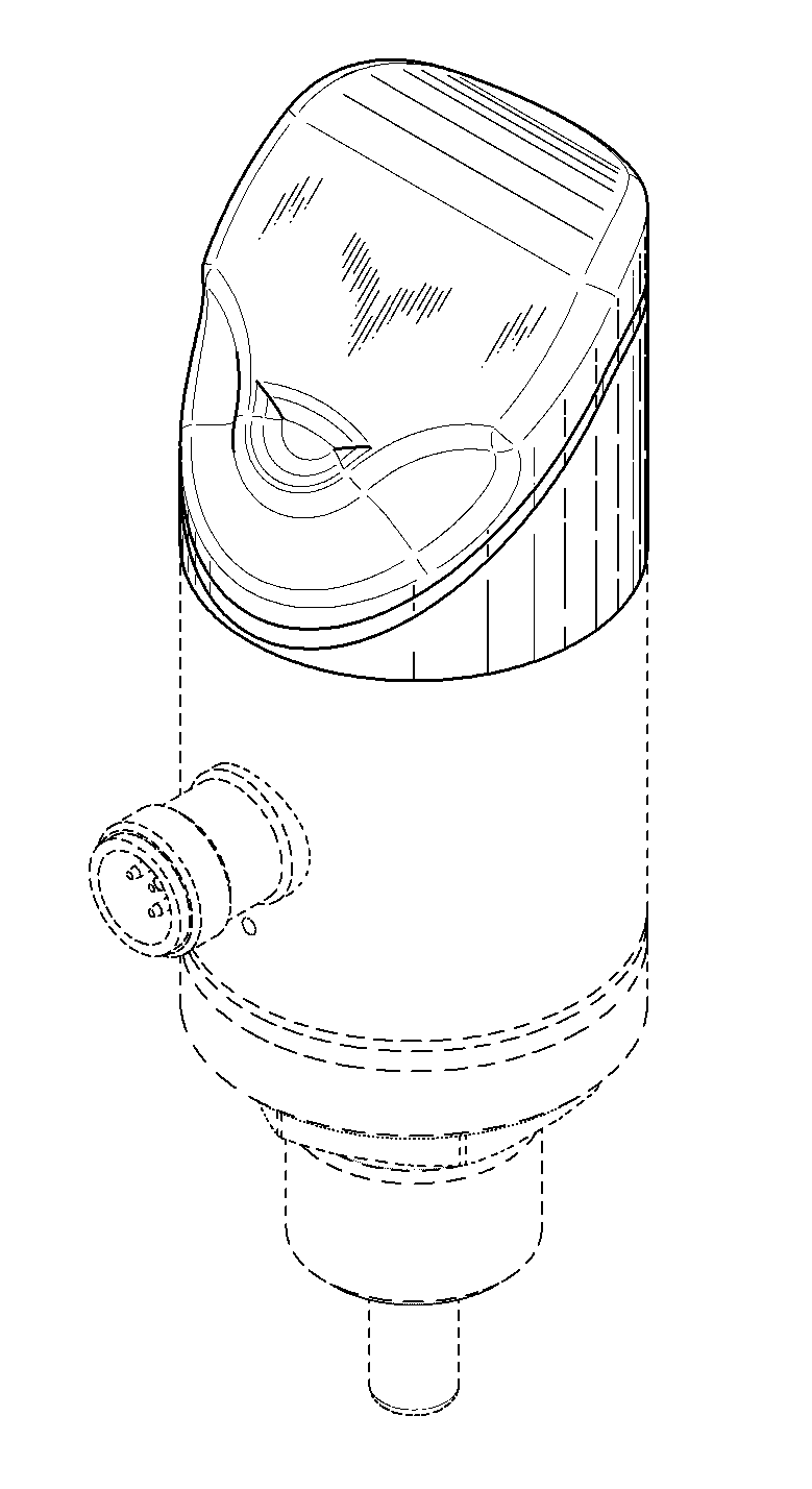
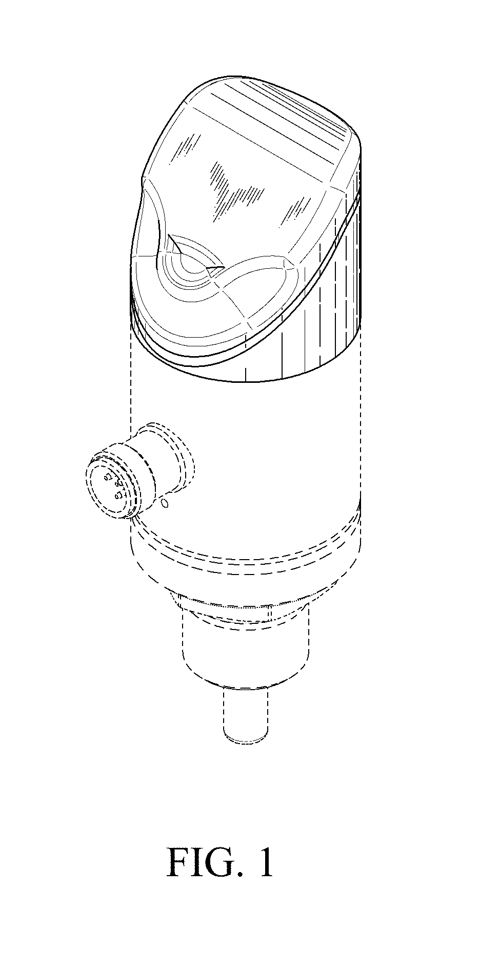
FIG. 1 is a front left side isometric view of a casing for a measuring instrument in accordance with the new design;
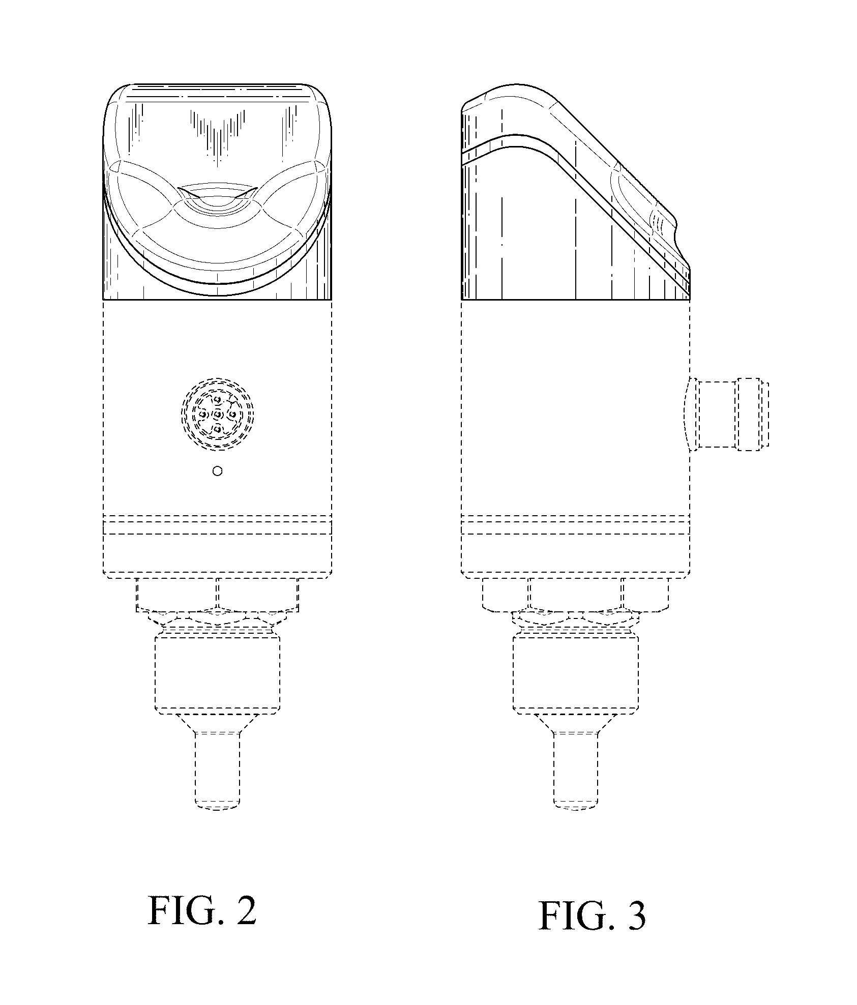
FIG. 2 is a front elevational view thereof;
FIG. 3 is a right side elevational view thereof;
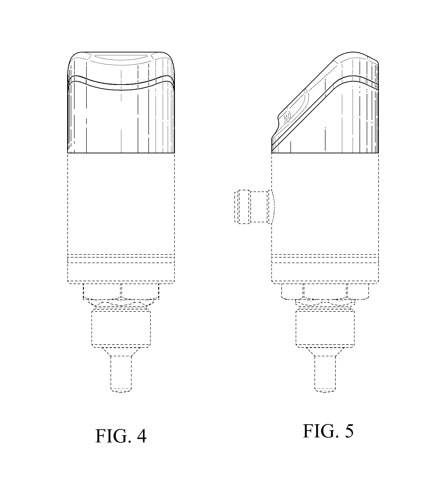
FIG. 4 is a rear elevational view thereof;
FIG. 5 is a left side elevational view thereof;
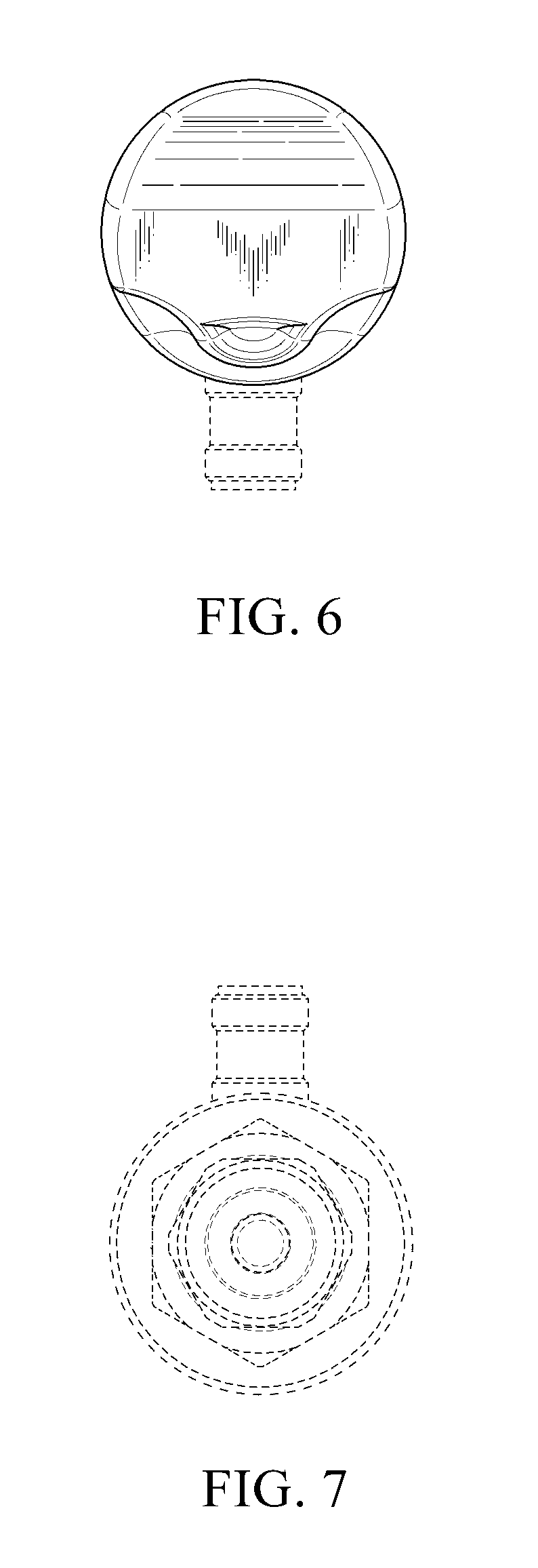
FIG. 6 is a top plan view thereof; and,
FIG. 7 is a bottom plan view thereof.
The broken lines shown in the drawings illustrate portions of the article that form no part of the claimed design.
* * * * *
References
D00000
D00001
D00002
D00003
D00004
XML
uspto.report is an independent third-party trademark research tool that is not affiliated, endorsed, or sponsored by the United States Patent and Trademark Office (USPTO) or any other governmental organization. The information provided by uspto.report is based on publicly available data at the time of writing and is intended for informational purposes only.
While we strive to provide accurate and up-to-date information, we do not guarantee the accuracy, completeness, reliability, or suitability of the information displayed on this site. The use of this site is at your own risk. Any reliance you place on such information is therefore strictly at your own risk.
All official trademark data, including owner information, should be verified by visiting the official USPTO website at www.uspto.gov. This site is not intended to replace professional legal advice and should not be used as a substitute for consulting with a legal professional who is knowledgeable about trademark law.