Accessory mount
Preus , et al. Feb
U.S. patent number D841,444 [Application Number D/560,845] was granted by the patent office on 2019-02-26 for accessory mount. This patent grant is currently assigned to TTI (MACAO COMMERCIAL OFFSHORE) LIMITED. The grantee listed for this patent is TTI (Macao Commerical Offshore) Limited. Invention is credited to J. Luke Jenkins, C. Eric Lagman, Taku Ohi, Parke Pleasants, Michael Preus, John Schaalje, Steven Westover.


| United States Patent | D841,444 |
| Preus , et al. | February 26, 2019 |
Accessory mount
Claims
CLAIM We claim the ornamental design for an accessory mount, as shown and described.
| Inventors: | Preus; Michael (Greenville, SC), Pleasants; Parke (Anderson, SC), Jenkins; J. Luke (Anderson, SC), Schaalje; John (Williamson, SC), Ohi; Taku (Greer, SC), Westover; Steven (Anderson, SC), Lagman; C. Eric (Anderson, SC) | ||||||||||
|---|---|---|---|---|---|---|---|---|---|---|---|
| Applicant: |
|
||||||||||
| Assignee: | TTI (MACAO COMMERCIAL OFFSHORE)
LIMITED (Macau, MO) |
||||||||||
| Appl. No.: | D/560,845 | ||||||||||
| Filed: | April 11, 2016 |
| Current U.S. Class: | D8/367 |
| Current International Class: | 0805 |
| Field of Search: | ;D8/339,349,350-353,371,373,380,382-383,394,396,404,499,367 ;D30/119 ;D23/411 |
References Cited [Referenced By]
U.S. Patent Documents
| 4064404 | December 1977 | Willmott et al. |
| D252216 | June 1979 | Whitney, Jr. |
| 4538661 | September 1985 | Henry et al. |
| 5589747 | December 1996 | Utke |
| D393506 | April 1998 | Ohi |
| 6002346 | December 1999 | Bowden et al. |
| 6027148 | February 2000 | Shoemaker |
| 6089626 | July 2000 | Shoemaker |
| 6124822 | September 2000 | Wu |
| 6191706 | February 2001 | Kositkun |
| 6218962 | April 2001 | Fiene |
| 6310548 | October 2001 | Stephens, Jr. et al. |
| D458863 | June 2002 | Harding |
| 6469464 | October 2002 | McCall |
| D472091 | March 2003 | Bell |
| 6683431 | January 2004 | Fitzgibbon et al. |
| 6911898 | June 2005 | Chung |
| 6946973 | September 2005 | Yanda |
| 6975203 | December 2005 | Brookbank et al. |
| 6989760 | January 2006 | Dierking et al. |
| 7057547 | June 2006 | Olmsted et al. |
| 7145470 | December 2006 | Hoermann |
| 7194412 | March 2007 | Mays |
| 7265508 | September 2007 | Karasek et al. |
| 7683794 | March 2010 | Contreras |
| 7688014 | March 2010 | Tang et al. |
| D623660 | September 2010 | Kieffer |
| 7996231 | August 2011 | Mays |
| 8011633 | September 2011 | Huang |
| 8077054 | December 2011 | Aarons |
| 8330570 | December 2012 | Martin |
| 8330573 | December 2012 | Crucs |
| D682663 | May 2013 | Evon |
| D685998 | July 2013 | Robbins, III |
| 8542093 | September 2013 | Rodriguez et al. |
| D691027 | October 2013 | Rainer |
| D697388 | January 2014 | Pan |
| D700828 | March 2014 | Goodman |
| D704038 | May 2014 | Roethler |
| 8766768 | July 2014 | Martin |
| 8786435 | July 2014 | Barnett et al. |
| 8810433 | August 2014 | Aarons |
| D714621 | October 2014 | Pan |
| D714623 | October 2014 | Pan |
| 8866583 | October 2014 | Ordaz |
| D720984 | January 2015 | Privitera |
| D722954 | February 2015 | James |
| 9347468 | May 2016 | Eisenkolb |
| D761638 | July 2016 | Johnson |
| D774635 | December 2016 | Kruska |
| D785145 | April 2017 | He |
| D786787 | May 2017 | Yang |
| D790408 | June 2017 | Wymore |
| D799022 | October 2017 | Ksiazek |
| D799670 | October 2017 | McDonnell |
| D804739 | December 2017 | Ksiazek |
| D805182 | December 2017 | Pickett |
| D806650 | January 2018 | Chang |
| D808001 | January 2018 | Berkman |
| D808510 | January 2018 | Gajewski |
| D810269 | February 2018 | Sanders |
| D810911 | February 2018 | Hoss |
| D810973 | February 2018 | Jacq |
| D811090 | February 2018 | Karl |
| 2002/0140576 | October 2002 | Simon |
| 2003/0160705 | August 2003 | Guetz |
| 2007/0235149 | November 2007 | Hillar et al. |
| 2008/0079570 | April 2008 | Fineman et al. |
| 2009/0313898 | December 2009 | Manaras |
| 2010/0058669 | March 2010 | Cole |
| 2011/0199234 | August 2011 | Butler, III et al. |
| 2012/0192852 | August 2012 | Whitmire |
| 2013/0081329 | April 2013 | French et al. |
| 2014/0007505 | January 2014 | Manaras |
| 2014/0259927 | September 2014 | McNally, II |
| 2017/0099074 | April 2017 | Richardson |
| 2017/0150847 | June 2017 | Feng |
| 2017/0295658 | October 2017 | Whitmire |
| 1790814 | May 2007 | EP | |||
| 3193220 | Dec 2001 | WO | |||
| 2007047720 | Apr 2007 | WO | |||
| 2012171756 | Dec 2012 | WO | |||
Assistant Examiner: Buckner; Nathaniel D.
Attorney, Agent or Firm: Michael Best & Friedrich LLP
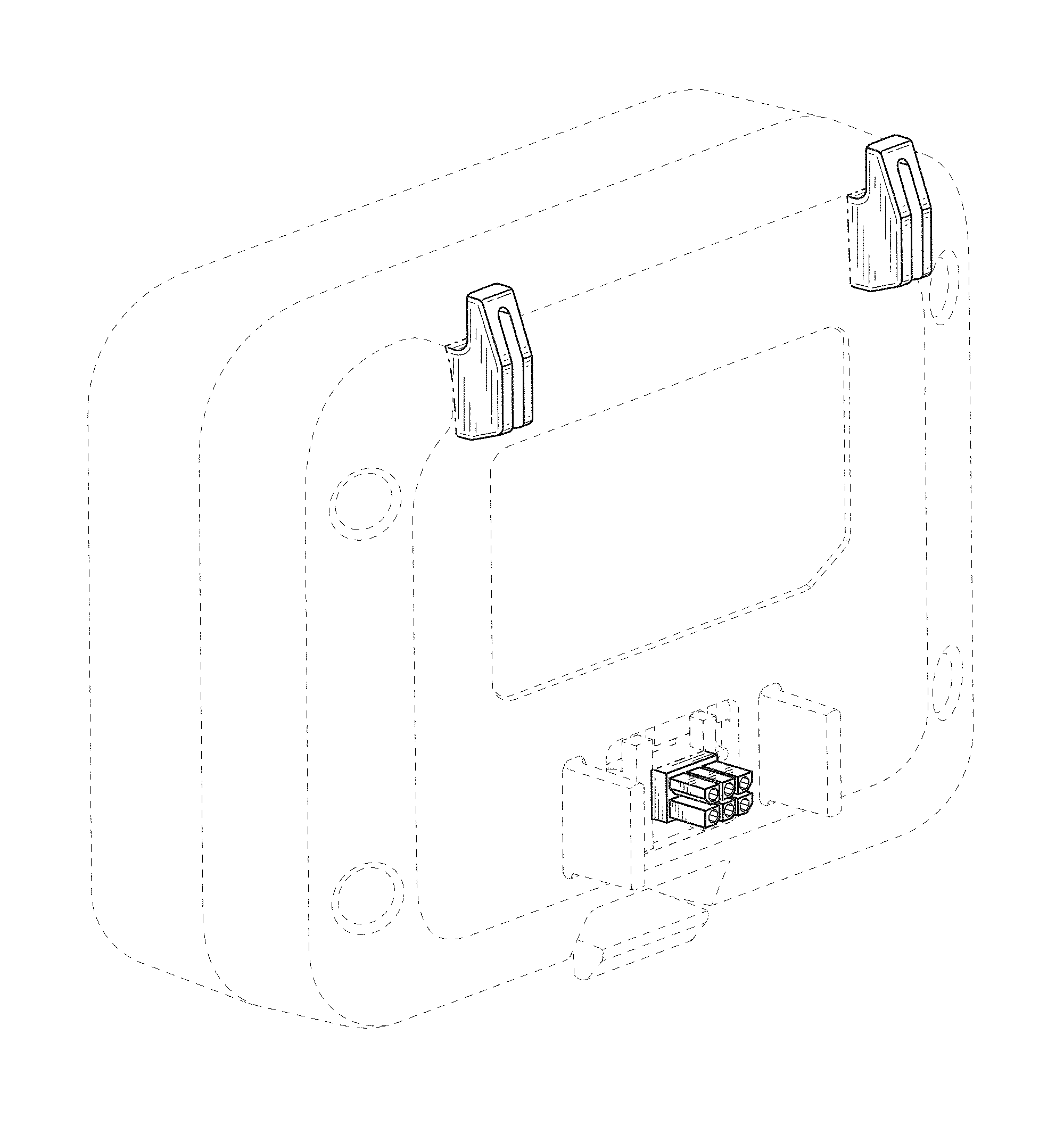
Description
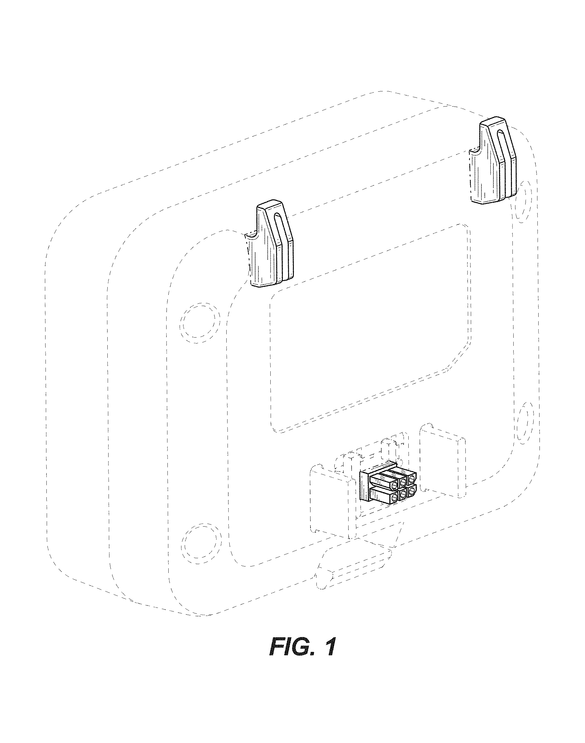
FIG. 1 is a perspective view of an accessory mount according to an embodiment of the invention.
FIG. 2 is a front view of the accessory mount of FIG. 1.
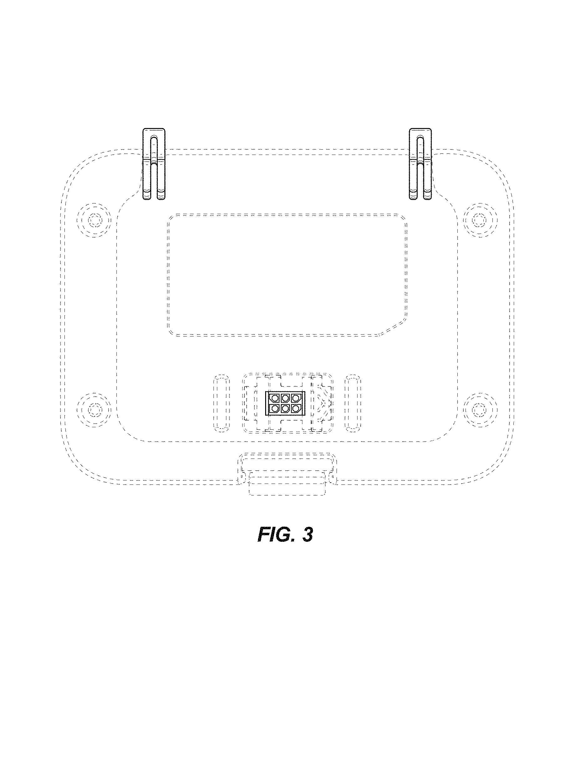
FIG. 3 is a rear view of the accessory mount of FIG. 1.
FIG. 4 is a first side view of the accessory mount of FIG. 1.
FIG. 5 is a second side view of the accessory mount of FIG. 1.
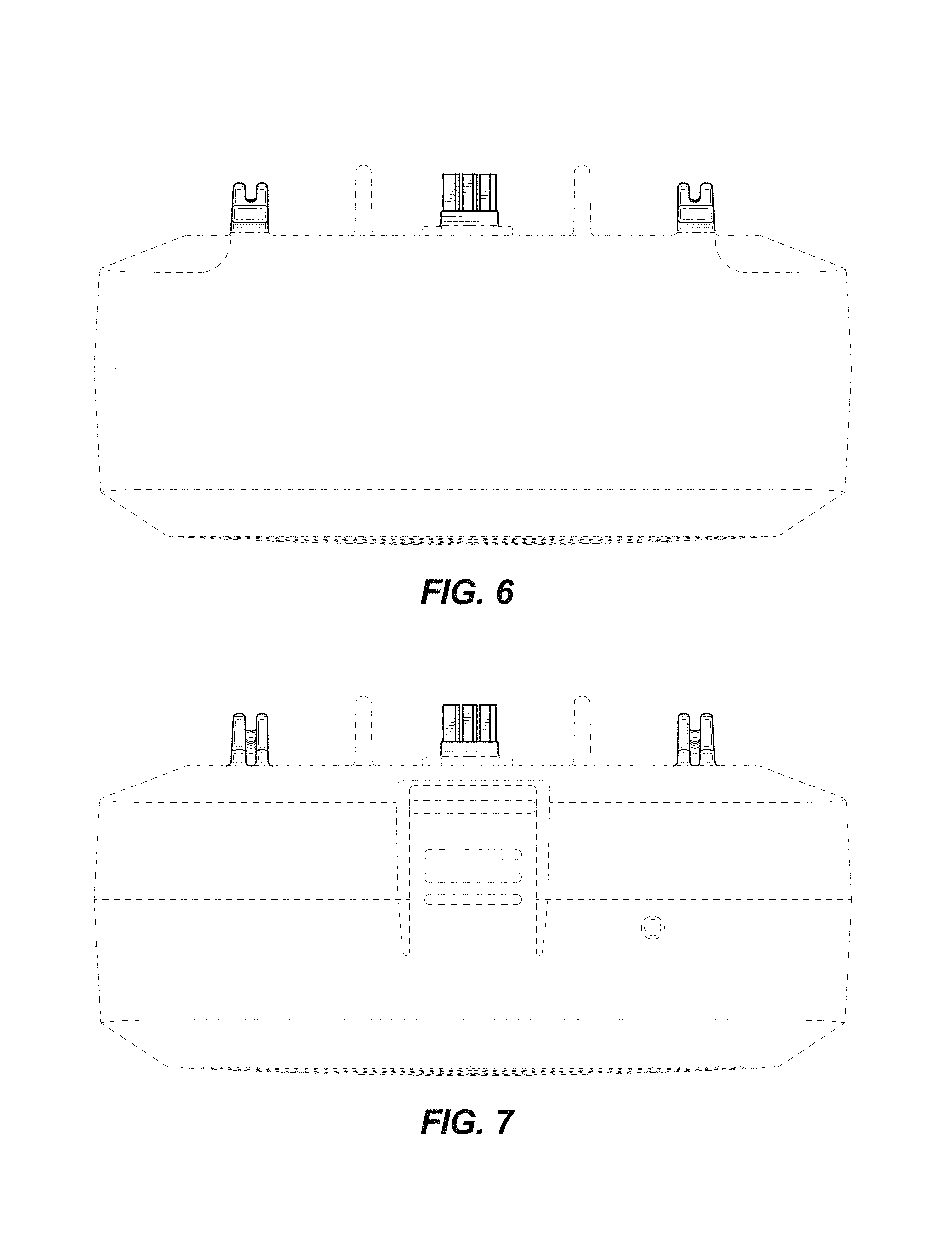
FIG. 6 is a top view of the accessory mount of FIG. 1; and,
FIG. 7 is a bottom view of the accessory mount of FIG. 1.
The portions of the accessory mount shown in broken lines are included for the purpose of illustrating environment and form no part of the claimed design. The portions of the accessory mount shown in broken lines having unequal length segments illustrate the boundary of the claimed design and form no part of the claimed design.
* * * * *
D00000
D00001
D00002
D00003
D00004
D00005
XML
uspto.report is an independent third-party trademark research tool that is not affiliated, endorsed, or sponsored by the United States Patent and Trademark Office (USPTO) or any other governmental organization. The information provided by uspto.report is based on publicly available data at the time of writing and is intended for informational purposes only.
While we strive to provide accurate and up-to-date information, we do not guarantee the accuracy, completeness, reliability, or suitability of the information displayed on this site. The use of this site is at your own risk. Any reliance you place on such information is therefore strictly at your own risk.
All official trademark data, including owner information, should be verified by visiting the official USPTO website at www.uspto.gov. This site is not intended to replace professional legal advice and should not be used as a substitute for consulting with a legal professional who is knowledgeable about trademark law.