Drape ring
Geller , et al. Feb
U.S. patent number D840,458 [Application Number D/621,792] was granted by the patent office on 2019-02-12 for drape ring. This patent grant is currently assigned to Carl Zeiss Meditec AG. The grantee listed for this patent is Carl Zeiss Meditec AG. Invention is credited to Nadine Geller, Frank Koenig, Daniel Lindner.


| United States Patent | D840,458 |
| Geller , et al. | February 12, 2019 |
Drape ring
Claims
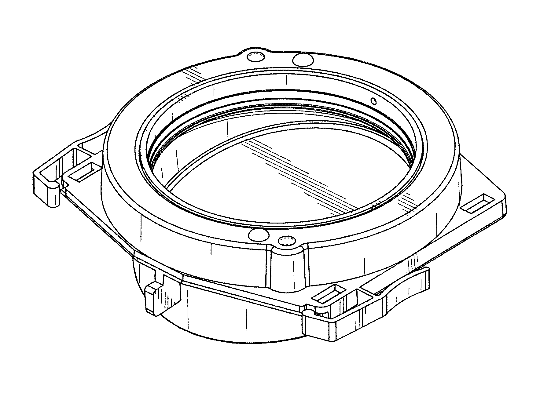
CLAIM The ornamental design for a drape ring, as shown and described.
| Inventors: | Geller; Nadine (Koenigsbronn, DE), Lindner; Daniel (Koenigsbronn, DE), Koenig; Frank (Aalen, DE) | ||||||||||
|---|---|---|---|---|---|---|---|---|---|---|---|
| Applicant: |
|
||||||||||
| Assignee: | Carl Zeiss Meditec AG (Jena,
DE) |
||||||||||
| Appl. No.: | D/621,792 | ||||||||||
| Filed: | October 11, 2017 |
Related U.S. Patent Documents
| Application Number | Filing Date | Patent Number | Issue Date | ||
|---|---|---|---|---|---|
| 29567833 | Jun 13, 2016 | ||||
Foreign Application Priority Data
| Dec 11, 2015 [EM] | 002907030 | |||
| Current U.S. Class: | D16/131 |
| Current International Class: | 1606 |
| Field of Search: | ;D16/130-136,217,218,219,245,208 |
References Cited [Referenced By]
U.S. Patent Documents
| D198141 | May 1964 | Armbruster |
| D198142 | May 1964 | Armbruster |
| D235578 | June 1975 | Miyake et al. |
| D252833 | September 1979 | Bowser |
| 4307950 | December 1981 | Suzuki et al. |
| 5155624 | October 1992 | Flagler |
| D339599 | September 1993 | Tiffen |
| 5311358 | May 1994 | Pederson et al. |
| 5608574 | March 1997 | Heinrich |
| 5682264 | October 1997 | Cleveland et al. |
| 5876328 | March 1999 | Fox |
| 6024454 | February 2000 | Horan |
| 6026244 | February 2000 | Tanaka |
| D425930 | May 2000 | Kurisu |
| D435586 | December 2000 | Kunihiro et al. |
| 6270266 | August 2001 | Fukuda et al. |
| 6876503 | April 2005 | Weaver et al. |
| D505147 | May 2005 | Koren |
| 7232230 | June 2007 | Bala |
| D649993 | December 2011 | Ding |
| D721750 | January 2015 | Teetzel et al. |
| D723078 | February 2015 | Nauli et al. |
| D723600 | March 2015 | Nauli et al. |
| 2001/0038499 | November 2001 | Baartman |
| 2004/0156100 | August 2004 | Fuchs |
| 2004/0190140 | September 2004 | Bala |
| 2005/0094269 | May 2005 | Moses et al. |
| 2005/0286130 | December 2005 | Bala |
| 2007/0064309 | March 2007 | Luloh |
| 2008/0144178 | June 2008 | Dillon et al. |
| 2010/0238551 | September 2010 | Hubbs |
| 2017/0168292 | June 2017 | Koenig et al. |
Other References
|
Drape Rings | Surgical Drapes with VisionGuard Lens | Zeiss, posted date N/A/, (c) N/A Zeiss International, [online],[site visited Mar. 28, 2018], Available at https://www.zeiss.com/meditec/int/products/spine-surgery/surgical-microsc- opes/opmi-vario-700.html#options---accessories. cited by examiner. |
Primary Examiner: Snapp; Sandra S
Assistant Examiner: Thurman; Holly E
Attorney, Agent or Firm: Walter Ottesen, P.A.
Description
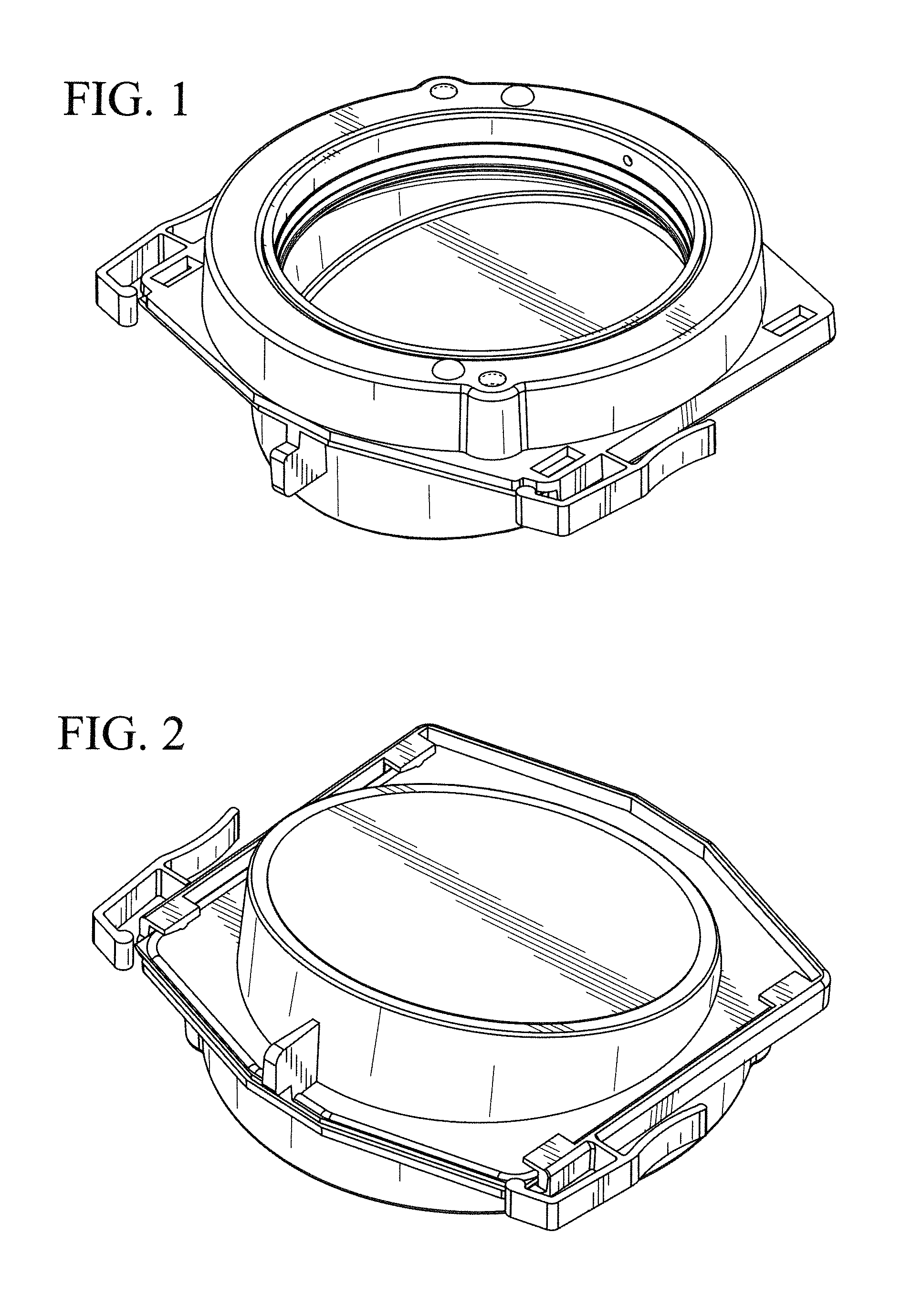
FIG. 1 is a top perspective view of a drape ring of our new design;
FIG. 2 is a bottom perspective view of the drape ring of FIG. 1;
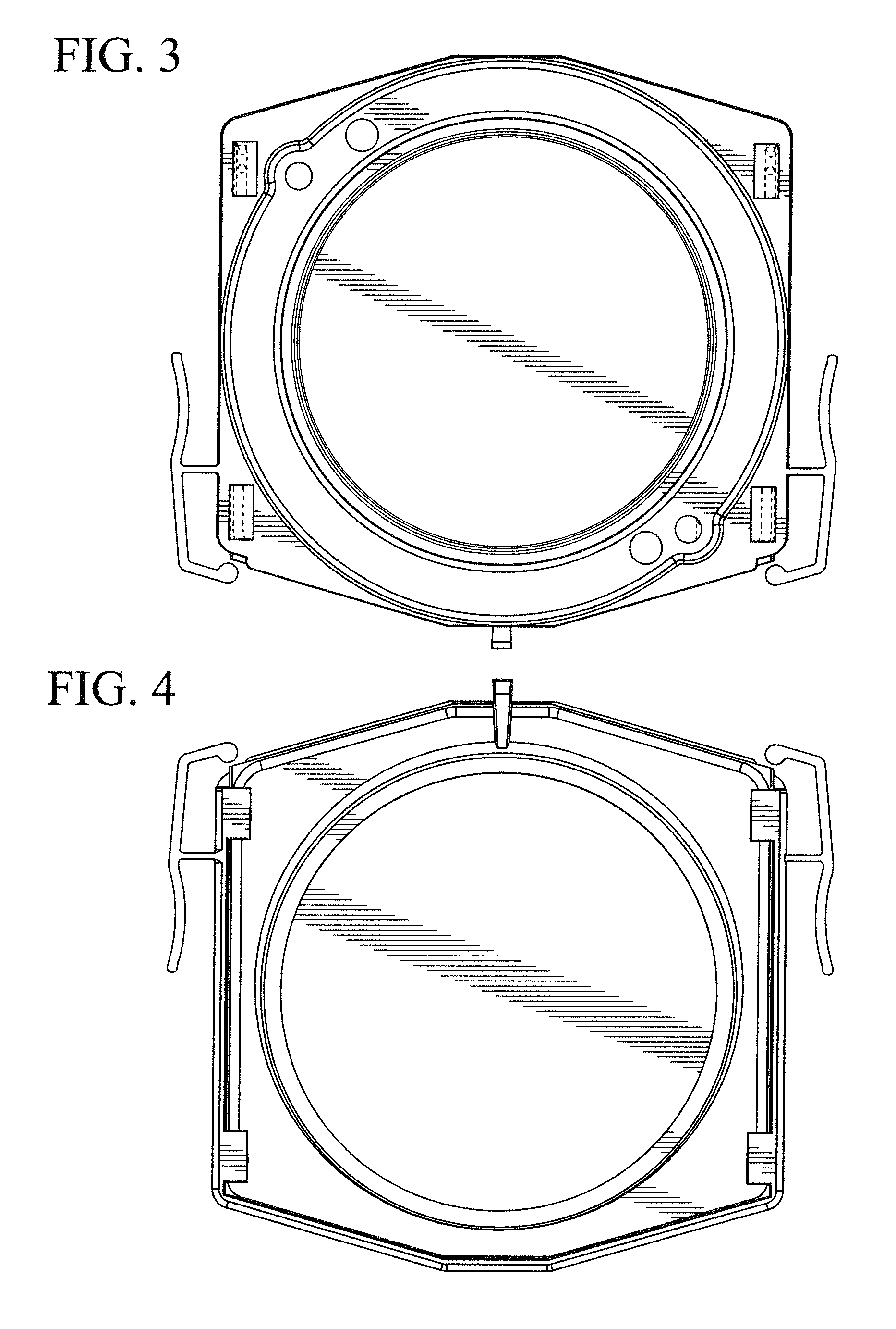
FIG. 3 is a top plan view of the drape ring of FIG. 1;
FIG. 4 is a bottom plan view of the drape ring of FIG. 1;
FIG. 5 is a front elevation view of the drape ring of FIG. 1;
FIG. 6 is a rear elevation view of the drape ring of FIG. 1;
FIG. 7 is a left side elevation view of the drape ring of FIG. 1; and,
FIG. 8 is a right side elevation view of the drape ring of FIG. 1.
The broken lines depict portions of the drape ring that form no part of the claimed design.
* * * * *
References
D00000
D00001
D00002
D00003
D00004
XML
uspto.report is an independent third-party trademark research tool that is not affiliated, endorsed, or sponsored by the United States Patent and Trademark Office (USPTO) or any other governmental organization. The information provided by uspto.report is based on publicly available data at the time of writing and is intended for informational purposes only.
While we strive to provide accurate and up-to-date information, we do not guarantee the accuracy, completeness, reliability, or suitability of the information displayed on this site. The use of this site is at your own risk. Any reliance you place on such information is therefore strictly at your own risk.
All official trademark data, including owner information, should be verified by visiting the official USPTO website at www.uspto.gov. This site is not intended to replace professional legal advice and should not be used as a substitute for consulting with a legal professional who is knowledgeable about trademark law.