Electronic device
Son , et al. Feb
U.S. patent number D840,394 [Application Number D/617,109] was granted by the patent office on 2019-02-12 for electronic device. This patent grant is currently assigned to Samsung Electronics Co., Ltd.. The grantee listed for this patent is Samsung Electronics Co., Ltd.. Invention is credited to Seung-Ho Jang, Chung-Ha Kim, Jang-Woon Kim, Jun-Won Lee, Hyun-Keun Son.


View All Diagrams
| United States Patent | D840,394 |
| Son , et al. | February 12, 2019 |
Electronic device
Claims
CLAIM We claim the ornamental design for an electronic device, as shown and described.
| Inventors: | Son; Hyun-Keun (Seoul, KR), Lee; Jun-Won (Seongnam-si, KR), Kim; Jang-Woon (Seoul, KR), Kim; Chung-Ha (Seoul, KR), Jang; Seung-Ho (Seongnam-si, KR) | ||||||||||
|---|---|---|---|---|---|---|---|---|---|---|---|
| Applicant: |
|
||||||||||
| Assignee: | Samsung Electronics Co., Ltd.
(Suwon-si, KR) |
||||||||||
| Appl. No.: | D/617,109 | ||||||||||
| Filed: | September 12, 2017 |
Foreign Application Priority Data
| Mar 14, 2017 [KR] | 30-2017-0011872 | |||
| Current U.S. Class: | D14/345; D14/138R |
| Current International Class: | 1402 |
| Field of Search: | ;D14/341-347,125-134,137,138R,138AA,138AB,138C,138G,147,203.1,203.3,203.4,203.7,218,247,248,332,336,371,374-377,388,389,315-318,420,426,429,440,448,450,489,492,496 ;D6/300-310 ;D10/50,65,98,104.1 ;D16/241 ;D18/4.6,6 ;D20/10,19,39 ;D21/329,330 |
References Cited [Referenced By]
U.S. Patent Documents
| D588126 | March 2009 | Chiang |
| D601992 | October 2009 | Choi |
| D680527 | April 2013 | Reeves |
| D714244 | September 2014 | Lee |
| D716750 | November 2014 | Matsumoto |
| D719540 | December 2014 | Lee |
| D739402 | September 2015 | Seoc |
| D746285 | December 2015 | Okabe |
| D749571 | February 2016 | Park |
| D769209 | October 2016 | Byun |
| D772225 | November 2016 | Kacin et al. |
| 9489080 | November 2016 | Seo |
| D775598 | January 2017 | Kim |
| D810073 | February 2018 | Bae |
| D825513 | August 2018 | Seo |
| 002220996-0002 | Jun 2013 | EM | |||
| 002234666-0001 | Jul 2013 | EM | |||
Other References
|
ZTE Axon M with two displays, a new trend in smartphones?, posted Oct. 18, 2017, [retrieved Aug. 23, 2018]. Retrieved from Internet, < URL: http://dunyanews.tv/en/Technology/410348-ZTE-Axon-M-with-two-displays-cou- ld-be-a-new-trend-in-smartphone-industry >. cited by examiner . Samsung Galaxy X Foldable Smartphone Gets 3D Trailer, posted Mar. 22, 2017, [retrieved Aug. 23, 2018]. Retrieved from Internet, < URL: https://www.concept-phones.com/samsung/samsung-galaxy-foldable-smartphone- -3d-trailer-video/ >. cited by examiner. |
Primary Examiner: Fox; Barbara
Assistant Examiner: Reed; Kristin E
Attorney, Agent or Firm: NSIP Law
Description
FIG. 1 is a front perspective view of an electronic device showing our new design;
FIG. 2 is a front elevational view thereof;
FIG. 3 is a rear elevational view thereof;
FIG. 4 is a left-side elevational view thereof;
FIG. 5 is a right-side elevational view thereof;
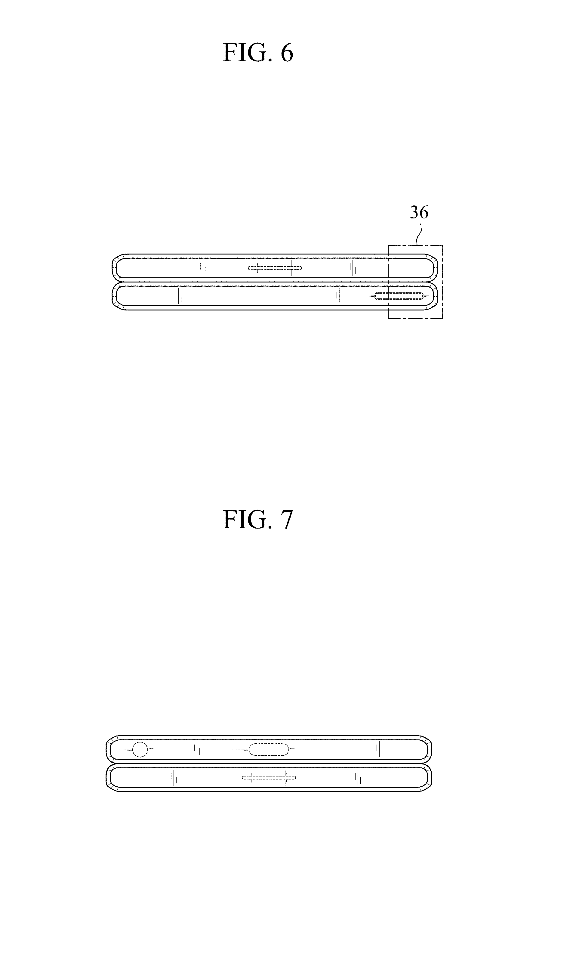
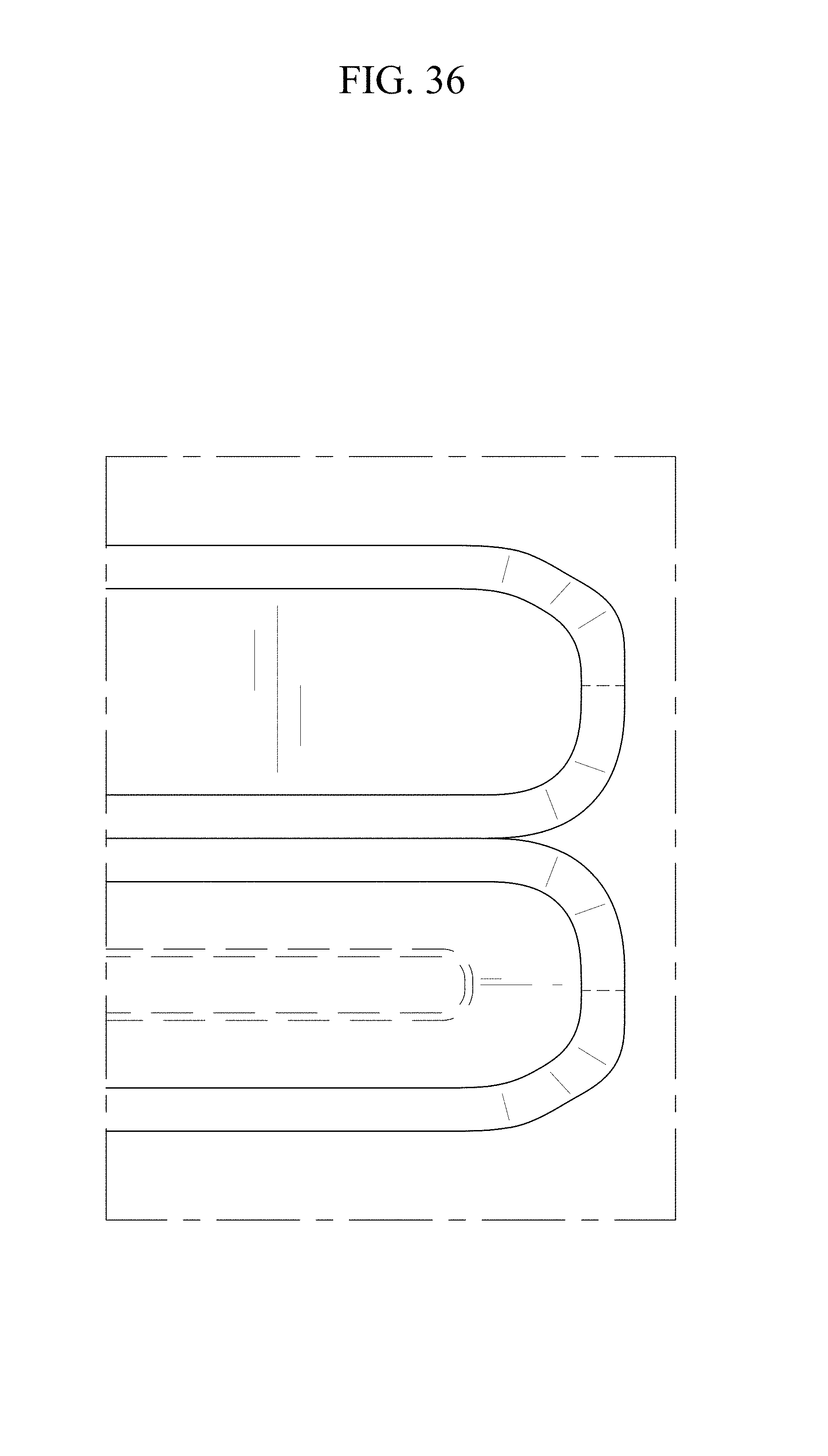
FIG. 6 is a top plan view thereof;
FIG. 7 is a bottom plan view thereof;
FIG. 8 is another perspective view thereof showing the electronic device in a first partially open position;
FIG. 9 is a front elevational view thereof;
FIG. 10 is a rear elevational view thereof;
FIG. 11 is a left-side elevational view thereof;
FIG. 12 is a right-side elevational view thereof;
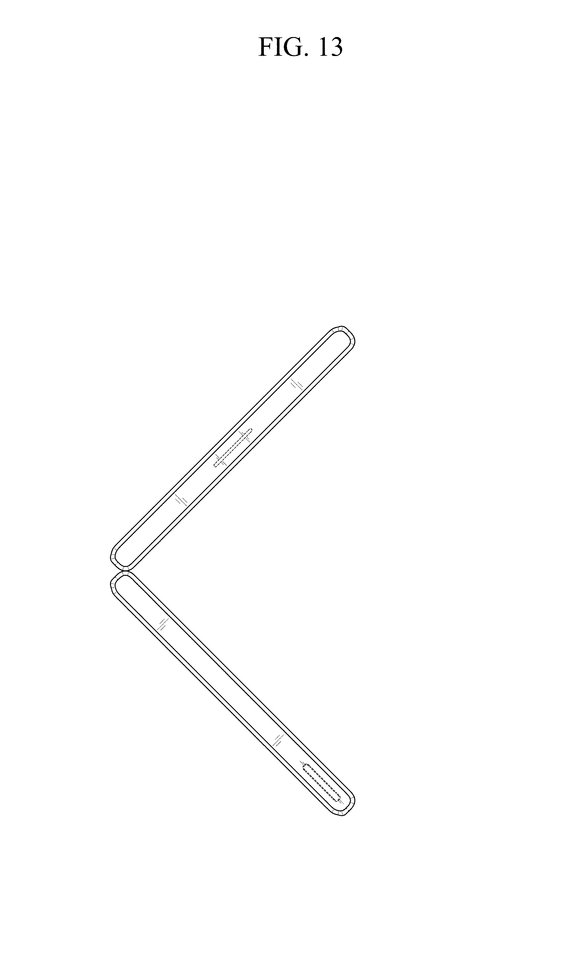
FIG. 13 is a top plan view thereof;
FIG. 14 is a bottom plan view thereof;
FIG. 15 is another perspective view thereof showing the electronic device in a second partially open position;
FIG. 16 is a front elevational view thereof;
FIG. 17 is a rear elevational view thereof;
FIG. 18 is a left-side elevational view thereof;
FIG. 19 is a right-side elevational view thereof;
FIG. 20 is a top plan view thereof;
FIG. 21 is a bottom plan view thereof;
FIG. 22 is another perspective view thereof showing the electronic device in a third partially open position;
FIG. 23 is a front elevational view thereof;
FIG. 24 is a rear elevational view thereof;
FIG. 25 is a left-side elevational view thereof;
FIG. 26 is a right-side elevational view thereof;
FIG. 27 is a top plan view thereof;
FIG. 28 is a bottom plan view thereof;
FIG. 29 is another perspective view thereof showing the electronic device in an open position;
FIG. 30 is a front elevational view thereof;
FIG. 31 is a rear elevational view thereof;
FIG. 32 is a left-side elevational view thereof;
FIG. 33 is a right-side elevational view thereof;
FIG. 34 is a top plan view thereof;
FIG. 35 is a bottom plan view thereof; and,
FIG. 36 is an enlarged view of the encircled portion in FIG. 6.
The evenly dashed broken lines in the figures show portions of the electronic device which form no part of the claimed design.
The dot-dashed broken lines encircling portions of the claimed design that are illustrated in enlargements form no part of the claimed design.
* * * * *
References
D00000
D00001
D00002
D00003
D00004
D00005
D00006
D00007
D00008
D00009
D00010
D00011
D00012
D00013

D00014

D00015

D00016

D00017

D00018

D00019

D00020

D00021

D00022

D00023

D00024

D00025

D00026

D00027

D00028

D00029

D00030

D00031

D00032

D00033

D00034
XML
uspto.report is an independent third-party trademark research tool that is not affiliated, endorsed, or sponsored by the United States Patent and Trademark Office (USPTO) or any other governmental organization. The information provided by uspto.report is based on publicly available data at the time of writing and is intended for informational purposes only.
While we strive to provide accurate and up-to-date information, we do not guarantee the accuracy, completeness, reliability, or suitability of the information displayed on this site. The use of this site is at your own risk. Any reliance you place on such information is therefore strictly at your own risk.
All official trademark data, including owner information, should be verified by visiting the official USPTO website at www.uspto.gov. This site is not intended to replace professional legal advice and should not be used as a substitute for consulting with a legal professional who is knowledgeable about trademark law.