Control module
Altonen , et al. Fe
U.S. patent number D839,846 [Application Number D/601,961] was granted by the patent office on 2019-02-05 for control module. This patent grant is currently assigned to Lutron Electronics Co., Inc.. The grantee listed for this patent is Lutron Electronics Co., Inc.. Invention is credited to Gregory Altonen, Nicholas R. Baer, Jason C. Killo, Noel Mayo, Sean R. Pearson.


| United States Patent | D839,846 |
| Altonen , et al. | February 5, 2019 |
Control module
Claims
CLAIM The ornamental design for a control module, to be applied to a lighting fixture, as shown and described.
| Inventors: | Altonen; Gregory (Easton, PA), Baer; Nicholas R. (Emmaus, PA), Killo; Jason C. (Emmaus, PA), Mayo; Noel (Philadelphia, PA), Pearson; Sean R. (Allentown, PA) | ||||||||||
|---|---|---|---|---|---|---|---|---|---|---|---|
| Applicant: |
|
||||||||||
| Assignee: | Lutron Electronics Co., Inc.
(Coopersburg, PA) |
||||||||||
| Appl. No.: | D/601,961 | ||||||||||
| Filed: | April 27, 2017 |
| Current U.S. Class: | D13/171 |
| Current International Class: | 1303 |
| Field of Search: | ;D13/162,171,173,174 |
References Cited [Referenced By]
U.S. Patent Documents
| D205357 | July 1966 | Stevenson |
| 4388503 | June 1983 | Penland |
| D310202 | August 1990 | Suck |
| D339543 | September 1993 | Martin |
| 5475192 | December 1995 | Inagaki |
| 6100484 | August 2000 | Houze |
| D464329 | October 2002 | Mainiero |
| D533846 | December 2006 | Burton |
| D562779 | February 2008 | Lamoree |
| 7470869 | December 2008 | Lin |
| D613669 | April 2010 | Collins |
| 8494663 | July 2013 | Lamoree |
| D687366 | August 2013 | Fujino |
| D703496 | April 2014 | Arcati |
| D752224 | March 2016 | Park |
| D777687 | January 2017 | Seidl |
| 9561853 | February 2017 | Fujino |
| 2010/0270138 | October 2010 | Yamanaka |
| 2010/0300859 | December 2010 | Prest |
| 2016/0314915 | October 2016 | Chen |
| 2017/0178833 | June 2017 | Mizuno |
Attorney, Agent or Firm: Saidman DesignLaw Group, LLC
Description
FIG. 1 is a perspective view of a control module, to be applied to a lighting fixture, showing our new design;
FIG. 2 is a front view thereof;
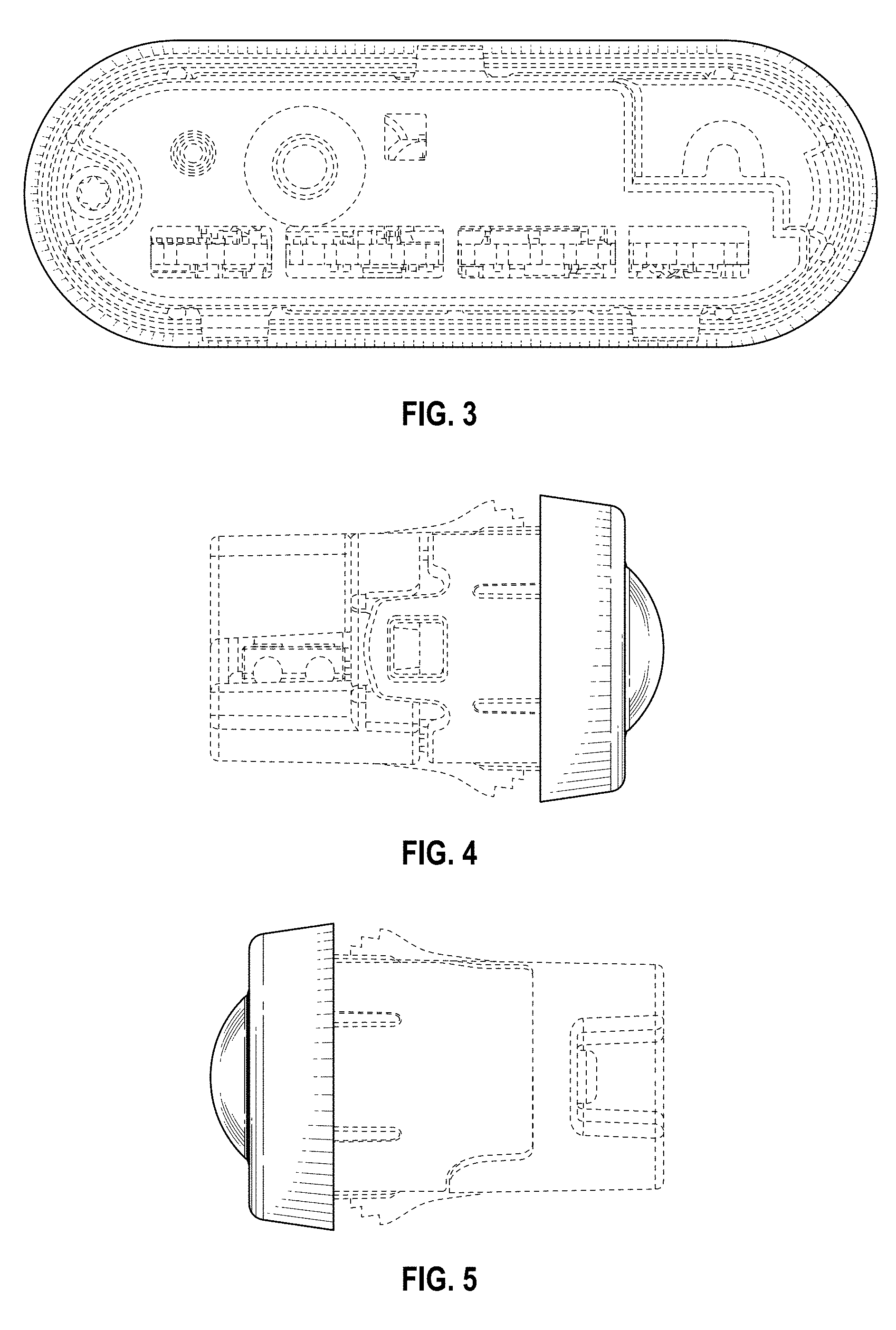
FIG. 3 is a rear view thereof;
FIG. 4 is a left side view thereof;
FIG. 5 is a right side view thereof;
FIG. 6 is a top view thereof; and,
FIG. 7 is a bottom view thereof.
The broken lines illustrate structure or features which form no part of the claimed design.
The drawings include surface shading which represents contour and not surface ornamentation.
* * * * *
D00000
D00001
D00002
D00003
XML
uspto.report is an independent third-party trademark research tool that is not affiliated, endorsed, or sponsored by the United States Patent and Trademark Office (USPTO) or any other governmental organization. The information provided by uspto.report is based on publicly available data at the time of writing and is intended for informational purposes only.
While we strive to provide accurate and up-to-date information, we do not guarantee the accuracy, completeness, reliability, or suitability of the information displayed on this site. The use of this site is at your own risk. Any reliance you place on such information is therefore strictly at your own risk.
All official trademark data, including owner information, should be verified by visiting the official USPTO website at www.uspto.gov. This site is not intended to replace professional legal advice and should not be used as a substitute for consulting with a legal professional who is knowledgeable about trademark law.