Earphone case
Son , et al. Ja
U.S. patent number D838,480 [Application Number D/565,151] was granted by the patent office on 2019-01-22 for earphone case. This patent grant is currently assigned to Samsung Electronics Co., Ltd.. The grantee listed for this patent is Samsung Electronics Co., Ltd.. Invention is credited to Rhys Bonahoom, Grace Lee, Jiyeon Lee, Dennis Miloseski, Howard Nuk, Seounghyun Son.


View All Diagrams
| United States Patent | D838,480 |
| Son , et al. | January 22, 2019 |
Earphone case
Claims
CLAIM We claim the ornamental design for an earphone case, as shown and described.
| Inventors: | Son; Seounghyun (San Francisco, CA), Nuk; Howard (San Francisco, CA), Miloseski; Dennis (Danville, CA), Bonahoom; Rhys (San Mateo, CA), Lee; Grace (San Francisco, CA), Lee; Jiyeon (Emeryville, CA) | ||||||||||
|---|---|---|---|---|---|---|---|---|---|---|---|
| Applicant: |
|
||||||||||
| Assignee: | Samsung Electronics Co., Ltd.
(Suwon-si, KR) |
||||||||||
| Appl. No.: | D/565,151 | ||||||||||
| Filed: | May 18, 2016 |
| Current U.S. Class: | D3/294 |
| Current International Class: | 0301 |
| Field of Search: | ;D14/204,223 ;D3/201,203.1,204,205,212,294,298 ;D9/414,721,730 |
References Cited [Referenced By]
U.S. Patent Documents
| 4703519 | October 1987 | Krenzel |
| D501714 | February 2005 | Trybus |
| D506744 | June 2005 | Andre et al. |
| D637584 | May 2011 | Peller |
| D740018 | October 2015 | Zhang |
| D772572 | November 2016 | Palmborg |
| D793717 | August 2017 | Boljat |
| D810421 | February 2018 | Ross |
| D817640 | May 2018 | Dang |
| D818268 | May 2018 | Akana |
| 30-2011-0006112 | May 2012 | KR | |||
Attorney, Agent or Firm: NSIP Law
Description
FIG. 1 is a front perspective view of an earphone case showing our new design;
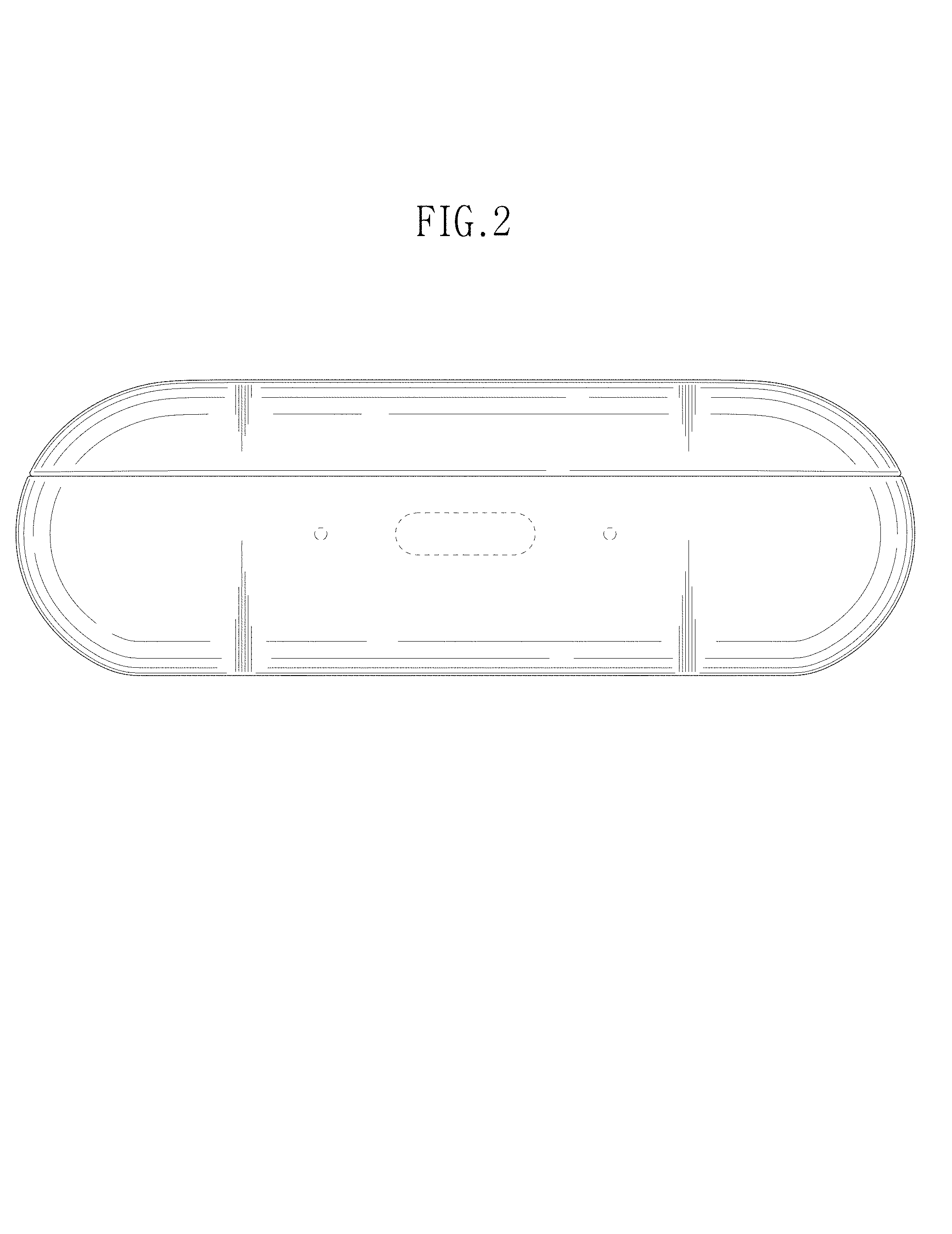
FIG. 2 is a front view thereof;
FIG. 3 is a rear view thereof;
FIG. 4 is a left-side view thereof;
FIG. 5 is a right-side view thereof;
FIG. 6 is a top plan view thereof;
FIG. 7 is a bottom plan view thereof;
FIG. 8 is a perspective view of the earphone case of FIG. 1 shown in an open position.
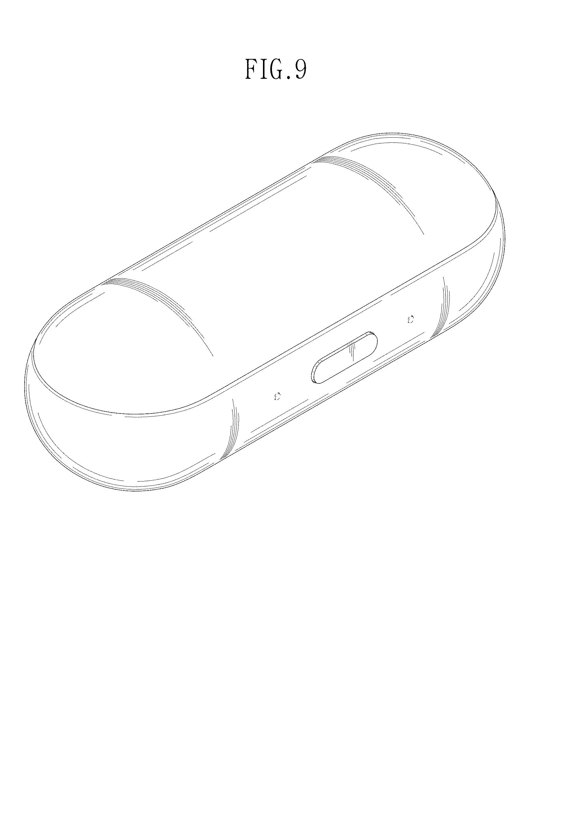
FIG. 9 is a front perspective view of another embodiment of an earphone case showing our new design;
FIG. 10 is a front view of FIG. 9;
FIG. 11 is a rear view of FIG. 9;
FIG. 12 is a left side view of FIG. 9;
FIG. 13 is a right-side view of FIG. 9;
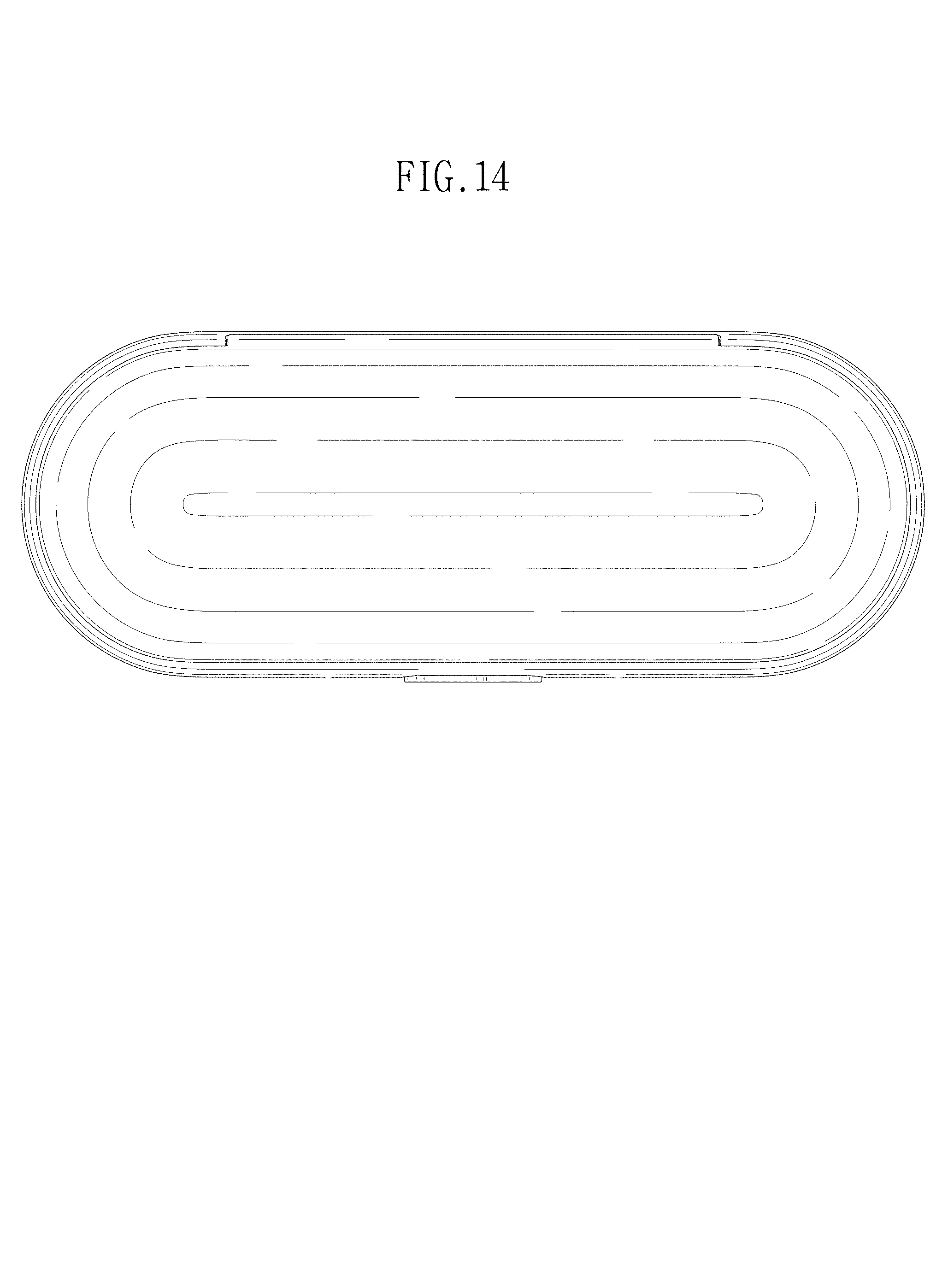
FIG. 14 is a top plan view of FIG. 9;
FIG. 15 is a bottom plan view of FIG. 9; and,
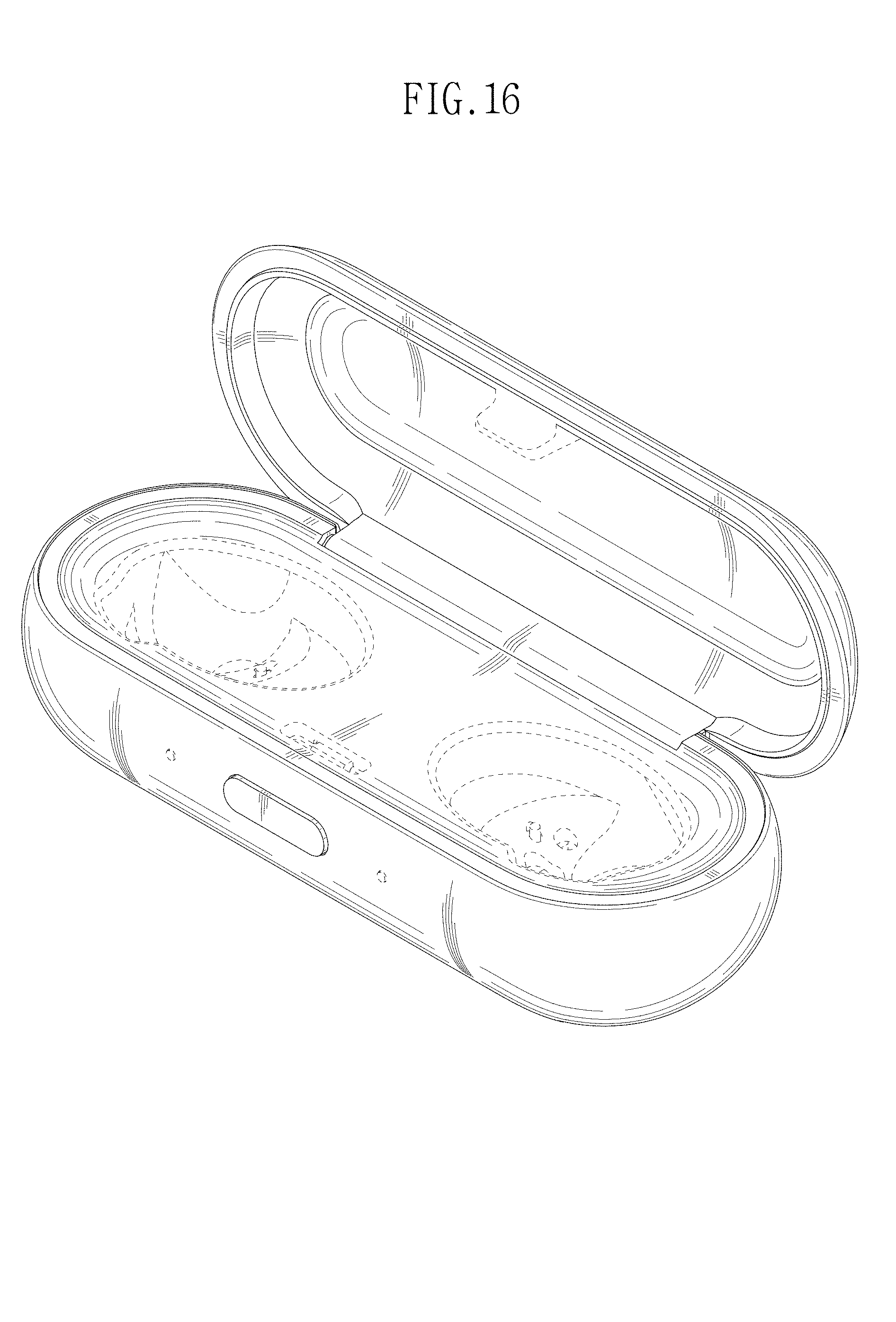
FIG. 16 is a perspective view of the earphone case of FIG. 9 shown in an open position.
The broken line shown in FIGS. 1 through 11 and 14 through 16 is included for the purpose of illustrating portions of the earphone case that do not form a part of the claimed design.
* * * * *
D00000
D00001
D00002
D00003
D00004
D00005
D00006
D00007
D00008
D00009
D00010
D00011
D00012
D00013

D00014
XML
uspto.report is an independent third-party trademark research tool that is not affiliated, endorsed, or sponsored by the United States Patent and Trademark Office (USPTO) or any other governmental organization. The information provided by uspto.report is based on publicly available data at the time of writing and is intended for informational purposes only.
While we strive to provide accurate and up-to-date information, we do not guarantee the accuracy, completeness, reliability, or suitability of the information displayed on this site. The use of this site is at your own risk. Any reliance you place on such information is therefore strictly at your own risk.
All official trademark data, including owner information, should be verified by visiting the official USPTO website at www.uspto.gov. This site is not intended to replace professional legal advice and should not be used as a substitute for consulting with a legal professional who is knowledgeable about trademark law.