Stove burner
Koch , et al. Ja
U.S. patent number D838,137 [Application Number D/588,465] was granted by the patent office on 2019-01-15 for stove burner. This patent grant is currently assigned to ISOPHORDING GMBH. The grantee listed for this patent is ISPHORDING GmbH. Invention is credited to Juergen Koch, Matthias Mueller.


| United States Patent | D838,137 |
| Koch , et al. | January 15, 2019 |
Stove burner
Claims
CLAIM The ornamental design for a stove burner, as shown and described.
| Inventors: | Koch; Juergen (Attendorn, DE), Mueller; Matthias (Attendorn, DE) | ||||||||||
|---|---|---|---|---|---|---|---|---|---|---|---|
| Applicant: |
|
||||||||||
| Assignee: | ISOPHORDING GMBH (Olpe,
DE) |
||||||||||
| Appl. No.: | D/588,465 | ||||||||||
| Filed: | December 21, 2016 |
| Current U.S. Class: | D7/407 |
| Current International Class: | 0702 |
| Field of Search: | ;D7/402-409,323,332-351,362-367,399,397,309,306 ;D23/386,397,402,415-419 ;D15/81 |
References Cited [Referenced By]
U.S. Patent Documents
| 947753 | January 1910 | Norstrand |
| 1330989 | February 1920 | Soults |
| 1663438 | March 1928 | Brumbaugh |
| 1681068 | August 1928 | Taylor |
| 1742897 | January 1930 | Brodbeck |
| 1764718 | June 1930 | Gercich |
| 1833734 | November 1931 | Brumbaugh |
| 1872019 | August 1932 | Taylor |
| 1878143 | September 1932 | Hobson |
| 1962819 | June 1934 | Hoffstetter |
| 1974222 | September 1934 | Teller |
| 2005242 | June 1935 | Rogers |
| 2138925 | December 1938 | Kahn |
Assistant Examiner: Shiflet; Nicole C
Attorney, Agent or Firm: Wilford; Andrew
Description
This application is related to commonly owned and copending U.S. patent application Ser. No. 29/579,796 filed Oct. 4, 2016, whose entire disclosure is incorporated herewith by reference.
FIG. 1 is a perspective view of a stove burner formed of a cover and a base shown in FIGS. 5-10;
FIG. 2 is a top view of the stove burner;
FIG. 3 is a front side view of the stove burner;
FIG. 4 is another perspective view of the stove burner shown in a broken line environment;
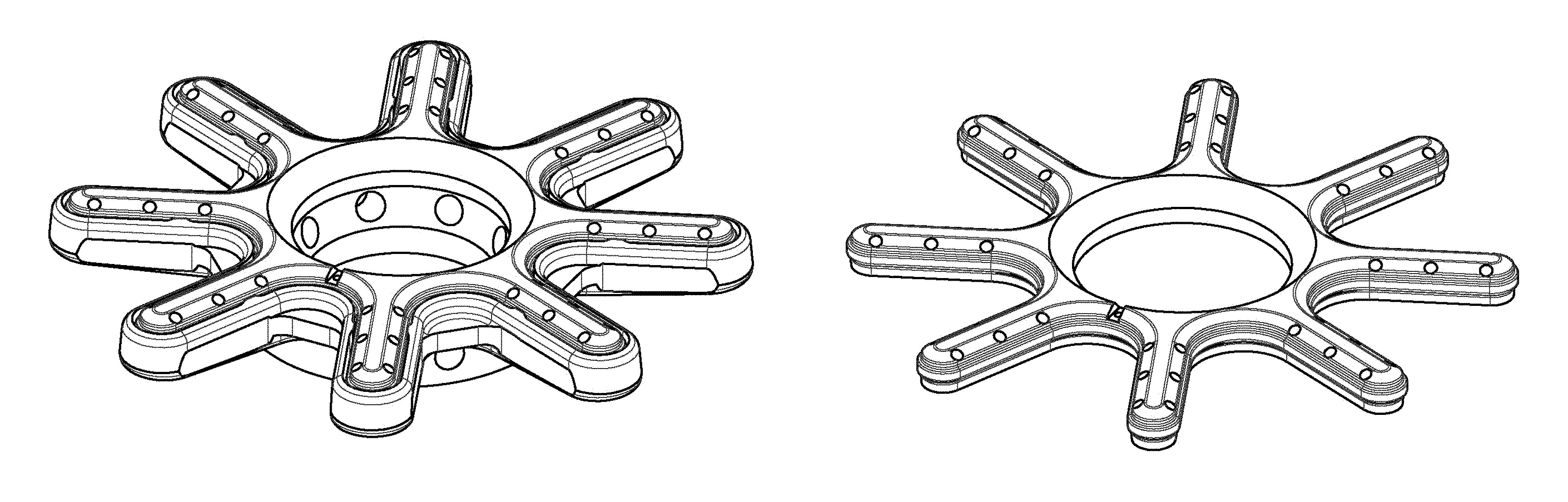
FIG. 5 is a perspective view of a burner cover according to the invention;
FIG. 6 is a top view of the burner cover;
FIG. 7 is a front side view of a burner base according to the invention;
FIG. 8 is a perspective view of the burner base;
FIG. 9 is a top view of the burner base; and,
FIG. 10 is a front side view of the burner cover.
In the drawing, disclaimed structures are illustrated with broken lines.
* * * * *
D00000
D00001
D00002
D00003
D00004
D00005
XML
uspto.report is an independent third-party trademark research tool that is not affiliated, endorsed, or sponsored by the United States Patent and Trademark Office (USPTO) or any other governmental organization. The information provided by uspto.report is based on publicly available data at the time of writing and is intended for informational purposes only.
While we strive to provide accurate and up-to-date information, we do not guarantee the accuracy, completeness, reliability, or suitability of the information displayed on this site. The use of this site is at your own risk. Any reliance you place on such information is therefore strictly at your own risk.
All official trademark data, including owner information, should be verified by visiting the official USPTO website at www.uspto.gov. This site is not intended to replace professional legal advice and should not be used as a substitute for consulting with a legal professional who is knowledgeable about trademark law.