Golf club shaft
Griffith , et al. J
U.S. patent number D837,320 [Application Number D/586,868] was granted by the patent office on 2019-01-01 for golf club shaft. This patent grant is currently assigned to TRUE TEMPER SPORTS, INC.. The grantee listed for this patent is True Temper Sports, Inc.. Invention is credited to James Boyce Barton, Gregory William Cavill, Michael Parker Gardner, Thomas Daniel Griffith.


| United States Patent | D837,320 |
| Griffith , et al. | January 1, 2019 |
| **Please see images for: ( Certificate of Correction ) ** |
Golf club shaft
Claims
CLAIM The ornamental design for a golf club shaft, as shown and described.
| Inventors: | Griffith; Thomas Daniel (Amory, MS), Gardner; Michael Parker (Amory, MS), Barton; James Boyce (Saltillo, MS), Cavill; Gregory William (Germantown, TN) | ||||||||||
|---|---|---|---|---|---|---|---|---|---|---|---|
| Applicant: |
|
||||||||||
| Assignee: | TRUE TEMPER SPORTS, INC.
(Memphis, TN) |
||||||||||
| Appl. No.: | D/586,868 | ||||||||||
| Filed: | December 7, 2016 |
| Current U.S. Class: | D21/757 |
| Current International Class: | 2102 |
| Field of Search: | ;D21/756-757 ;473/316-323 ;D8/315 |
References Cited [Referenced By]
U.S. Patent Documents
| D118594 | January 1940 | Heddon |
| D120333 | May 1940 | Barnhart |
| 2220852 | November 1940 | Scott |
| 2446622 | August 1948 | Turner |
| D236639 | September 1975 | Kanne |
| D236735 | September 1975 | Bush |
| D245441 | August 1977 | Middlestadt |
| D250356 | November 1978 | Kaugars |
| 4205845 | June 1980 | Kanne |
| D263330 | March 1982 | Kaugars |
| 4555112 | November 1985 | Masghati |
| 4563007 | January 1986 | Bayliss et al. |
| D351643 | October 1994 | Gubany |
| D356616 | March 1995 | Jacques |
| 5496028 | March 1996 | Chien |
| 5599242 | February 1997 | Solviche |
| D378771 | April 1997 | Antonious |
| 5653644 | August 1997 | Jaeckel |
| D385934 | November 1997 | You |
| 5735752 | April 1998 | Antonious |
| 5776008 | July 1998 | Lundberg |
| D401981 | December 1998 | Yoo |
| 5865688 | February 1999 | Bae |
| 5904628 | May 1999 | MacKay, Jr. |
| 5944618 | August 1999 | Cheng |
| D421783 | March 2000 | Ryu |
| 6117021 | September 2000 | Crow |
| 6231457 | May 2001 | Chen |
| 6302805 | October 2001 | Penley |
| 6354960 | March 2002 | Perryman |
| D466575 | December 2002 | Hedrick et al. |
| 6520867 | February 2003 | Miura |
| D507815 | July 2005 | Hedrick |
| D537498 | February 2007 | Brookshire-Herron |
| D558289 | December 2007 | Main |
| D561282 | February 2008 | Rollinson |
| D596254 | July 2009 | Shiga |
| D602107 | October 2009 | Shiga |
| D676911 | February 2013 | Brown, Jr. et al. |
| D686289 | July 2013 | Brown, Jr. et al. |
| 8758158 | June 2014 | Jennings |
| D737915 | September 2015 | Su |
| 2002/0077194 | June 2002 | Carr |
| 2002/0155899 | October 2002 | Ryu |
| 2005/0148404 | July 2005 | Ignatius |
| 2006/0128495 | June 2006 | Braly et al. |
| 0 724 895 | Aug 1996 | EP | |||
| 256049 | Aug 1926 | GB | |||
| 2000126344 | May 2000 | JP | |||
| 2002291951 | Oct 2002 | JP | |||
| WO 81/00521 | Mar 1981 | WO | |||
| WO 98/23338 | Jun 1998 | WO | |||
| WO 0139847 | Jun 2001 | WO | |||
Other References
|
Black & White drawing; True Temper Sports; 2011; 1 page. cited by applicant. |
Primary Examiner: Siegel; Mitchell I.
Attorney, Agent or Firm: Harness, Dickey & Pierce, P.L.C.
Description
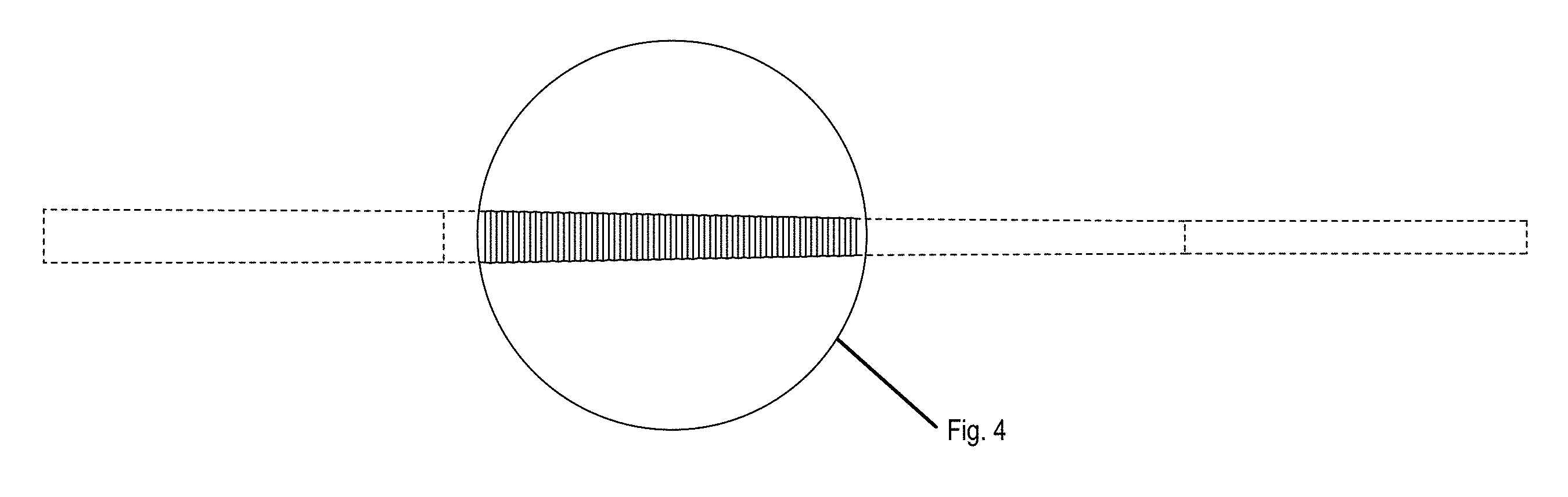
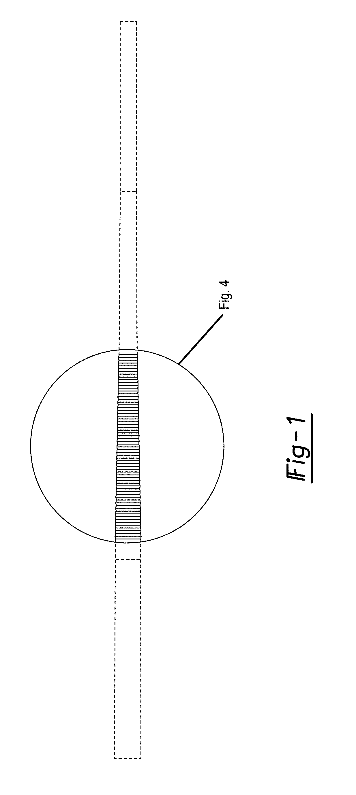
FIG. 1 is a front perspective view of the golf club shaft having a ripple section embodying our new design;
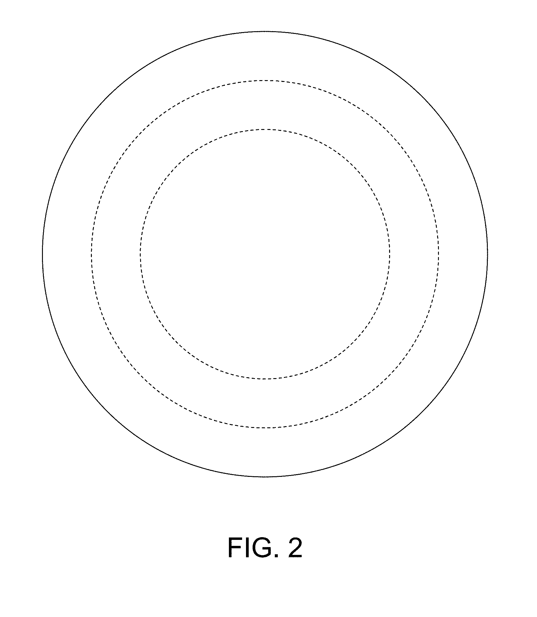
FIG. 2 is an enlarged grip end view of the golf club shaft;
FIG. 3 is an enlarged tip end view of the golf club shaft; and,
FIG. 4 is an enlarged front perspective view of the ripple section of the golf club shaft.
The golf shaft shown herein is tubular in configuration and circumferentially uniform. Therefore, the top, bottom and rear views of the golf shaft are identical to the front perspective view shown in FIGS. 1 and 4.
The broken lines showing the shaft are for illustrative purposes only and form no part of the claimed design.
* * * * *
D00000
D00001
D00002
D00003
D00004
XML
uspto.report is an independent third-party trademark research tool that is not affiliated, endorsed, or sponsored by the United States Patent and Trademark Office (USPTO) or any other governmental organization. The information provided by uspto.report is based on publicly available data at the time of writing and is intended for informational purposes only.
While we strive to provide accurate and up-to-date information, we do not guarantee the accuracy, completeness, reliability, or suitability of the information displayed on this site. The use of this site is at your own risk. Any reliance you place on such information is therefore strictly at your own risk.
All official trademark data, including owner information, should be verified by visiting the official USPTO website at www.uspto.gov. This site is not intended to replace professional legal advice and should not be used as a substitute for consulting with a legal professional who is knowledgeable about trademark law.