Method and apparatus for pre-forming a high tibial osteotomy
Maxson , et al. December 30, 2
U.S. patent number 8,920,512 [Application Number 13/720,644] was granted by the patent office on 2014-12-30 for method and apparatus for pre-forming a high tibial osteotomy. This patent grant is currently assigned to Biomet Sports Medicine, LLC. The grantee listed for this patent is Biomet Sports Medicine, LLC. Invention is credited to Gautam Gupta, William Maxson.


| United States Patent | 8,920,512 |
| Maxson , et al. | December 30, 2014 |
| **Please see images for: ( Certificate of Correction ) ** |
Method and apparatus for pre-forming a high tibial osteotomy
Abstract
An osteotomy implant including a porous portion, a solid portion, and a hinge portion. The porous portion includes a first part and a second part that defines a clearance therebetween. A solid portion abuts the porous portion. A hinge portion of the solid portion is coupled to the first part and the second part. The hinge portion is configured to enable the implant to be changed from a first configuration to a second configuration.
| Inventors: | Maxson; William (Fort Wayne, IN), Gupta; Gautam (Warsaw, IN) | ||||||||||
|---|---|---|---|---|---|---|---|---|---|---|---|
| Applicant: |
|
||||||||||
| Assignee: | Biomet Sports Medicine, LLC
(Warsaw, IN) |
||||||||||
| Family ID: | 49918838 | ||||||||||
| Appl. No.: | 13/720,644 | ||||||||||
| Filed: | December 19, 2012 |
Prior Publication Data
| Document Identifier | Publication Date | |
|---|---|---|
| US 20140172116 A1 | Jun 19, 2014 | |
| Current U.S. Class: | 623/23.51 |
| Current CPC Class: | A61F 2/28 (20130101); A61F 2/2846 (20130101); A61B 17/8095 (20130101); A61F 2002/30112 (20130101); A61F 2002/30736 (20130101); A61F 2002/2892 (20130101); A61F 2002/30538 (20130101); A61F 2250/0006 (20130101); A61F 2230/0013 (20130101); A61F 2002/30266 (20130101) |
| Current International Class: | A61F 2/28 (20060101) |
| Field of Search: | ;623/17.11-17.16 |
References Cited [Referenced By]
U.S. Patent Documents
| 4421112 | December 1983 | Mains et al. |
| 5053039 | October 1991 | Hofmann et al. |
| 5364402 | November 1994 | Mumme et al. |
| 5417694 | May 1995 | Marik et al. |
| 5613969 | March 1997 | Jenkins, Jr. |
| 5620448 | April 1997 | Puddu |
| 5722978 | March 1998 | Jenkins, Jr. |
| 5921988 | July 1999 | Legrand |
| 6086593 | July 2000 | Bonutti |
| 6514259 | February 2003 | Picard et al. |
| 6823871 | November 2004 | Schmieding |
| 7060074 | June 2006 | Rosa et al. |
| 7104997 | September 2006 | Lionberger et al. |
| 7121832 | October 2006 | Hsieh et al. |
| 7935119 | May 2011 | Ammann et al. |
| 7959637 | June 2011 | Fox et al. |
| 7967823 | June 2011 | Ammann et al. |
| 8062301 | November 2011 | Ammann et al. |
| 8083749 | December 2011 | Taber |
| 8133230 | March 2012 | Stevens et al. |
| 8137406 | March 2012 | Novak et al. |
| 8167951 | May 2012 | Ammann et al. |
| 8182489 | May 2012 | Horacek |
| 8192441 | June 2012 | Collazo |
| 8192495 | June 2012 | Simpson et al. |
| 8211112 | July 2012 | Novak et al. |
| 8241292 | August 2012 | Collazo |
| 8241293 | August 2012 | Stone et al. |
| 8265790 | September 2012 | Amiot et al. |
| 8303596 | November 2012 | Pla.beta.ky et al. |
| 8333772 | December 2012 | Fox et al. |
| 8355773 | January 2013 | Leitner et al. |
| 8632547 | January 2014 | Maxson et al. |
| 2003/0105526 | June 2003 | Bryant et al. |
| 2004/0153087 | August 2004 | Sanford et al. |
| 2005/0033432 | February 2005 | Gordon et al. |
| 2005/0075641 | April 2005 | Singhatat et al. |
| 2005/0228393 | October 2005 | Williams et al. |
| 2005/0234465 | October 2005 | McCombs et al. |
| 2005/0240195 | October 2005 | Axelson et al. |
| 2005/0273114 | December 2005 | Novak |
| 2006/0195111 | August 2006 | Couture |
| 2006/0200158 | September 2006 | Farling et al. |
| 2006/0241635 | October 2006 | Stumpo et al. |
| 2006/0241636 | October 2006 | Novak et al. |
| 2006/0293681 | December 2006 | Claypool et al. |
| 2007/0016209 | January 2007 | Ammann et al. |
| 2007/0118138 | May 2007 | Seo et al. |
| 2007/0244487 | October 2007 | Ammann et al. |
| 2007/0288029 | December 2007 | Justin et al. |
| 2007/0288030 | December 2007 | Metzger et al. |
| 2008/0015603 | January 2008 | Collazo |
| 2008/0015604 | January 2008 | Collazo |
| 2008/0015605 | January 2008 | Collazo |
| 2008/0039850 | February 2008 | Rowley et al. |
| 2008/0097451 | April 2008 | Chen et al. |
| 2008/0140081 | June 2008 | Heavener et al. |
| 2008/0140213 | June 2008 | Ammann et al. |
| 2008/0147073 | June 2008 | Ammann et al. |
| 2008/0161816 | July 2008 | Stevens et al. |
| 2008/0195109 | August 2008 | Hunter et al. |
| 2008/0287954 | November 2008 | Kunz et al. |
| 2008/0294170 | November 2008 | O'Brien |
| 2008/0306485 | December 2008 | Coon et al. |
| 2009/0076520 | March 2009 | Choi |
| 2009/0082774 | March 2009 | Oti et al. |
| 2009/0088759 | April 2009 | Aram et al. |
| 2009/0088760 | April 2009 | Aram et al. |
| 2009/0099567 | April 2009 | Zajac |
| 2009/0118769 | May 2009 | Sixto, Jr. et al. |
| 2009/0131942 | May 2009 | Aker et al. |
| 2009/0222015 | September 2009 | Park et al. |
| 2009/0248044 | October 2009 | Amiot et al. |
| 2009/0287217 | November 2009 | Ammann et al. |
| 2009/0318921 | December 2009 | White et al. |
| 2010/0010493 | January 2010 | Dower |
| 2010/0023015 | January 2010 | Park |
| 2010/0042105 | February 2010 | Park et al. |
| 2010/0049195 | February 2010 | Park et al. |
| 2010/0057088 | March 2010 | Shah |
| 2010/0121334 | May 2010 | Couture et al. |
| 2010/0145344 | June 2010 | Jordan et al. |
| 2010/0168752 | July 2010 | Edwards |
| 2010/0191244 | July 2010 | White et al. |
| 2010/0198224 | August 2010 | Metzger et al. |
| 2010/0212138 | August 2010 | Carroll et al. |
| 2010/0217338 | August 2010 | Carroll et al. |
| 2010/0318088 | December 2010 | Warne et al. |
| 2011/0015636 | January 2011 | Katrana et al. |
| 2011/0015639 | January 2011 | Metzger et al. |
| 2011/0022049 | January 2011 | Huebner et al. |
| 2011/0166578 | July 2011 | Stone et al. |
| 2011/0172672 | July 2011 | Dubeau et al. |
| 2011/0184419 | July 2011 | Meridew et al. |
| 2011/0218634 | September 2011 | Ringeisen |
| 2011/0251617 | October 2011 | Ammann et al. |
| 2011/0269100 | November 2011 | Furrer et al. |
| 2011/0275032 | November 2011 | Tardieu et al. |
| 2012/0109138 | May 2012 | Meridew et al. |
| 2012/0130382 | May 2012 | Iannotti et al. |
| 2012/0141034 | June 2012 | Iannotti et al. |
| 2012/0143197 | June 2012 | Lang et al. |
| 2012/0143267 | June 2012 | Iannotti et al. |
| 2012/0215225 | August 2012 | Philippon et al. |
| 2012/0221017 | August 2012 | Bonutti |
| 2012/0232596 | September 2012 | Ribeiro |
| 2012/0259335 | October 2012 | Scifert et al. |
| 2012/0271314 | October 2012 | Stemniski et al. |
| 2012/0276509 | November 2012 | Iannotti et al. |
| 2012/0283840 | November 2012 | Frederick et al. |
| 2012/0289965 | November 2012 | Gelaude et al. |
| 2012/0296339 | November 2012 | Iannotti et al. |
| 2012/0303004 | November 2012 | Uthgenannt et al. |
| 2012/0303033 | November 2012 | Weiner et al. |
| 2012/0310399 | December 2012 | Metzger |
| 2013/0006250 | January 2013 | Metzger et al. |
| 2013/0035766 | February 2013 | Meridew |
| 2013/0085500 | April 2013 | Meridew et al. |
| 2013/0110116 | May 2013 | Kehres et al. |
| 2013/0119579 | May 2013 | Iannotti et al. |
| 2013/0131681 | May 2013 | Katrana et al. |
| 2741525 | May 1997 | FR | |||
| 2771282 | May 1999 | FR | |||
Other References
|
"Arthrex.RTM. iBalance.RTM. HTO System for Medial Hight Tibial Opening Wedge Osteotomy--Surgical Technique," Medical brochure. (2013) 16 sheets. cited by applicant . "iBalance.RTM. HTO System Innovative Solutions for Varus Knee Realignment," Arthrex.RTM. medical brochure. (2013). 6 sheets. cited by applicant . "iBalance.RTM. Medial Opening Wedge Tibial System,"Arthrex.RTM.. (2011). 63 sheets. cited by applicant . "Pro Osteon.RTM. 200 R Bone Graft Substitute," Biomet brochure. (2014) 1 sheet. cited by applicant . "Pro Osteon.RTM. 500R Bone Graft Substitute," Biomet brochure. (2014) 1 sheet. cited by applicant . "Regenerex.RTM. Porous Titanium Construct," Biomet brochure. (2008) 12 sheets. cited by applicant . International Search Report and Written Opinion mailed Mar. 13, 2014 for PCT/US2013/074723 claiming benefit of U.S. Appl. No. 13/720,644, filed Dec. 19, 2012. cited by applicant. |
Primary Examiner: Isabella; David
Assistant Examiner: Schillinger; Ann
Attorney, Agent or Firm: Harness, Dickey
Claims
What is claimed is:
1. An osteotomy implant comprising: a porous portion including a first part with a first sidewall and a second part with a second sidewall, a clearance is defined between the first sidewall and the second sidewall; a solid portion abutting the porous portion, the first and the second sidewalls extending from the solid portion to define the clearance; and a hinge portion of the solid portion coupled to the first part and the second part; wherein the hinge portion is configured to enable the implant to be changed from a first configuration to a second configuration the implant further comprising an adjustment member, wherein the adjustment member extends from the first part to the second part across the clearance defined between the first part and the second part; wherein rotation of the adjustment member in a first direction draws the first part and the second part together, and rotation of the adjustment member in a second direction pushes the first part and the second part apart.
2. The osteotomy implant of claim 1, wherein the porous portion includes at least one of a metallic, PEEK, or PEKK.
3. The osteotomy implant of claim 1, wherein the porous portion includes a porous upper surface and a porous lower surface configured to receive bone ingrowth.
4. The osteotomy implant of claim 3, wherein the solid portion is coupled to an outer surface of the porous portion, the osteotomy implant formed by additive manufacturing.
5. The osteotomy implant of claim 4, wherein the solid portion is integral with the outer surface of the porous portion and is load bearing.
6. The osteotomy implant of claim 1, further comprising a plurality of solid, spaced apart, load bearing ribs with the porous portion therebetween.
7. The osteotomy implant of claim 1, wherein the solid portion includes at least one of a metallic, PEEK, or PEKK.
8. The osteotomy implant of claim 1, wherein the implant is monolithic.
9. An osteotomy implant comprising: a generally "U" shaped loadbearing porous portion including a first part and a second part, the first part includes a first inner surface that opposes a second inner surface of the second part, a clearance is defined between the first inner surface and the second inner surface; a solid portion coupled to both a first outer surface of the first part and a second outer surface of the second part, the first outer surface is opposite to the first inner surface and the second outer surface is opposite to the second inner surface; and a flexible hinge portion of the solid portion; wherein the implant is bendable at the flexible hinge portion to compress or expand the implant; wherein the flexible hinge portion is configured to enable the implant to be changed from a first configuration to a second configuration upon actuation of an adjustment member at the clearance, the first and the second parts are closer together in the second configuration than in the first configuration.
10. The osteotomy implant of claim 9, wherein both the porous portion and the solid portion include at least one of a metallic, PEEK, or PEKK.
11. The osteotomy implant of claim 9, wherein the adjustment member includes a fastener extending from the first part to the second part across the clearance defined between the first part and the second part, rotation of the fastener in a first direction draws the first part and the second part together, rotation of the fastener in a second direction pushes the first part and the second part apart.
12. The osteotomy implant of claim 9, wherein the adjustment member is arranged in the clearance and extends from the first part to the second part, actuation of the adjustment member in a first direction draws the first part and the second part together, actuation of the adjustment member in a second direction opposite to the first direction moves the first part and the second part apart.
13. The osteotomy implant of claim 9, wherein the first and the second inner surfaces extend directly from the solid portion.
14. The osteotomy implant of claim 13, wherein the first and the second inner surfaces extend linearly.
15. The osteotomy implant of claim 13, wherein the first and the second inner surfaces define the clearance as wedge-shaped.
16. An osteotomy implant comprising: a porous portion including a first part and a second part that defines a clearance therebetween; a solid portion abutting the porous portion; and a hinge portion of the solid portion coupled to the first part and the second part, the hinge portion is configured to enable the implant to be changed from a first configuration to a second configuration; and an adjustment member configured to change the implant from the first configuration to the second configuration; wherein the adjustment member includes a fastener extending from the first part to the second part across the clearance defined between the first part and the second part, rotation of the fastener in a first direction draws the first part and the second part together, rotation of the fastener in a second direction pushes the first part and the second part apart.
Description
FIELD
The present disclosure relates to a method and apparatus for pre-forming a high tibial osteotomy.
BACKGROUND
This section provides background information related to the present disclosure which is not necessarily prior art.
Various knee osteotomies are performed to adjust or change the orientation of the tibia to correct various abnormalities caused by birth defects, trauma, or disease. High tibial osteotomies include open-wedge and closed-wedge osteotomies. Various implants designed to fill osteotomies exist. Some are modeled after a patient's specific anatomy, which increases the cost of the implant and complexity of production. Therefore, a simplified and cost-effective osteotomy implant that can be adjusted to fit a patient's anatomy would be desirable.
SUMMARY
This section provides a general summary of the disclosure, and is not a comprehensive disclosure of its full scope or all of its features.
The present teachings provide for an osteotomy implant including a porous portion, a solid portion, and a hinge portion. The porous portion includes a first part and a second part that defines a clearance therebetween. A solid portion abuts the porous portion. A hinge portion of the solid portion is coupled to the first part and the second part. The hinge portion is configured to enable the implant to be changed from a first configuration to a second configuration.
The present teachings also provide for an osteotomy implant including a porous metallic portion, a solid metallic portion, and a metallic hinge portion. The porous metallic portion includes a first part spaced apart from a second part. The solid metallic portion is integral with the porous metallic portion. The metallic hinge portion of the solid metallic portion is one of aligned with or between the first part and the second part. The hinge portion is configured to enable the implant to be changed from a first configuration to a second configuration.
The present teachings also provide for an osteotomy implant including a generally "U" shaped loadbearing porous portion including a first part and a second part. The first part includes a first inner surface that opposes a second inner surface of the second part. A solid portion is coupled to both a first outer surface of the first part and a second outer surface of the second part. The first outer surface is opposite to the first inner surface and the second outer surface is opposite to the second inner surface. A flexible hinge portion is included with the solid portion. The implant is bendable at the flexible hinge portion to compress or expand the implant. The flexible hinge portion is configured to enable the implant to be changed from a first configuration to a second configuration.
Further areas of applicability will become apparent from the description provided herein. The description and specific examples in this summary are intended for purposes of illustration only and are not intended to limit the scope of the present disclosure.
DRAWINGS
The drawings described herein are for illustrative purposes only of selected embodiments and not all possible implementations, and are not intended to limit the scope of the present disclosure.
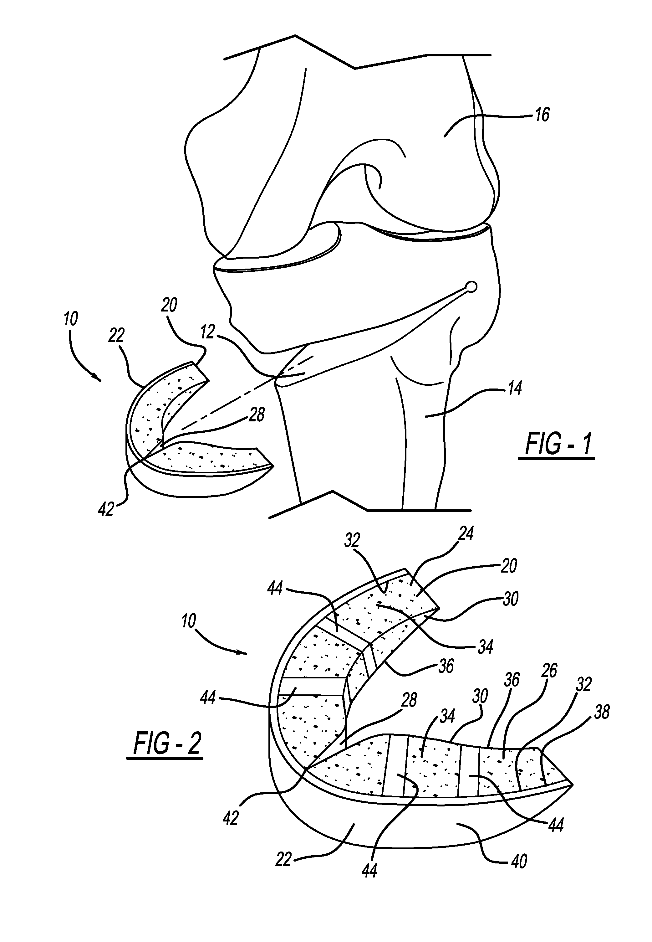
FIG. 1 illustrates an osteotomy implant according to the present teachings for implantation in an osteotomy site of a tibia bone;
FIG. 2 is a perspective view of the implant of FIG. 1;
FIG. 3 is a perspective view of another osteotomy implant according to the present teachings;
FIG. 4 is a perspective view of an additional osteotomy implant in accordance with the present teachings;
FIG. 5 is a top view of yet another osteotomy implant according to the present teachings;
FIG. 6 is a top view of still another osteotomy implant according to the present teachings; and
FIG. 7 is a top view of an additional osteotomy implant according to the present teachings.
Corresponding reference numerals indicate corresponding parts throughout the several views of the drawings.
DETAILED DESCRIPTION
Example embodiments will now be described more fully with reference to the accompanying drawings.
With initial reference to FIGS. 1 and 2, an osteotomy implant according to the present teachings is generally illustrated at reference numeral 10. As illustrated, the osteotomy implant 10 is for implantation at osteotomy site 12 of tibia 14. Femur 16 is also illustrated. The implant 10 can also be implanted at an osteotomy site in the femur 16, such as during a distal femoral osteotomy procedure.
The osteotomy implant 10 generally includes a porous portion 20 and a solid portion 22. The porous portion 20 generally includes a first part 24 and a second part 26, which define a clearance or gap 28 therebetween. Both the first part 24 and the second part 26 include an inner surface 30 and an outer surface 32, which is opposite to the inner surface 30. The first part 24 and the second part 26 are arranged such that the inner surface 30 of the first part 24 faces and is opposite to the inner surface 30 of the second part 26. Each of the first part 24 and the second part 26 further include an upper or superior surface 34, which is opposite to an under or inferior surface 36. The solid portion 22 includes an inner surface 38, which is opposite to an outer surface 40. The solid portion 22 extends across the outer surface 32 of each of the first part 24 and the second part 26 of the porous portion 20, and thus extends across the gap 28. The solid portion 22 includes a hinge 42, such as a living hinge, opposite to the gap 28.
The implant 10 can be made of any suitable biocompatible material sufficient to bear loads on the tibia 14 at the osteotomy site 12. For example, the implant 10 can be made out of a suitable metallic, such as titanium including commercially pure (CP) titanium or Grade 5 titanium alloy (Ti6Al4V). An example of a suitable porous titanium construct that the implant can be made from is Regenerex.RTM. by Biomet of Warsaw, Ind. Any suitable cobalt chrome based alloy may also be used. Both the porous portion 20 and the solid portion 22 can be made of the same material. The porous portion 20 can be made from any suitable implantable plastic, such as PEEK (polyether ether ketone) or PEKK (polyether ketone ketone). For example, the porous portion 20 can include ProOsteon.RTM. by Biomet of Warsaw, Ind.
The implant 10 can be manufactured in any suitable manner. For example, the porous portion 20 and the solid portion 22 can be individually manufactured and then subsequently coupled or joined together using any suitable coupling process. Other manufacturing processes that are suitable include electron beam melting or any suitable additive manufacturing process, such as a suitable additive metal fabrication technique. Using laser sintering, for example, the entire implant 10 can be manufactured or printed together, such that the porous portion 20 and the solid portion 22 are integrally formed and the implant 10 is monolithic. The porous portion 20 can be formed in any suitable manner that will provide for pores into which bone growth may occur in order to further secure the implant 10 at the osteotomy site 12. The porous portion 20 is a generally "U" shaped, load-bearing portion able to withstand loads upon the tibia 14. Upon being inserted into the osteotomy site 12, the implant 10 will be retained within the osteotomy site 12 through friction between the tibia 14 and the porous portion 20. The solid portion 22 further increases the compression strength of the implant 10 and prevents tissue from growing into the porous portion 20 from outside of the osteotomy site 12. The porous portion 22 may include ribs 44, which are not porous to further increase the compression strength of the implant 10.
Implantation of the implant 10 at the osteotomy site 12 will now be described. The implant 10 selected for implantation can be chosen from a plurality of implants 10 having a similar overall configuration, but having different general sizes to facilitate customization. For example, a plurality of implants 10 having different superior-inferior heights and medial-lateral widths can be provided and selected based on dimensions of the osteotomy size 12. The width of the implant 10 is first compared to the width of the osteotomy site 12 in the anterior to the posterior direction. The width of the implant 10 is generally considered with respect to the distance between the first part 24 and the second part 26 of the porous portion 20. If the width of the implant 10 is wider than the width of the osteotomy site 12, then the implant 10 can be compressed in order to decrease the width. If the width of the implant 10 is narrower than the width of the osteotomy site 12, then the implant 10 can be expanded in order to increase its width.
The implant 10 can be compressed (closed) or expanded (opened) either manually or using a suitable tool. The material of the solid portion 22 is rigid enough to maintain structural integrity of the implant 10, but flexible enough to permit the implant 10 to be compressed in this manner. As the first part 24 and the second part 26 are moved together, the gap 28 therebetween will become smaller. As the first part 24 and the second part 26 are moved apart, the gap 28 therebetween will become larger. Specifically, implant 10 pivots generally at the hinge 42, which can be configured in any suitable manner to facilitate bending of the solid portion 22, such as with a thinned portion, a notched portion, or any weakened portion. The first part 24 and the second part 26 can be compressed or expanded to any suitable position, such as between a first configuration and a second configuration, thus providing the implant 10 with a near infinite number of medial-lateral widths. The rigidity of the solid portion 22 will maintain the implant 10 in the compressed or expanded position to provide the implant 10 with a desired medial-lateral width to fit the osteotomy site 12. As the first part 24 and the second part 26 are moved, the solid portion 22 bends at the hinge 42. The implant 10 is retained within the osteotomy site 12 due to friction between the portion of the tibia 14 at the osteotomy site 12 and the porous portion 20. The implant 10 will be further retained within the osteotomy site 12 by bone ingrowth into the porous portion 20. The implant 10 can also be retained within the osteotomy site 12 with any suitable retention device or feature, such as a suitable locking plate.
With additional reference to FIG. 3, another osteotomy implant according to the present teachings is illustrated at reference numeral 50. The implant 50 is similar to the implant 10, and thus similar features are designated with similar reference numbers, and the description of these similar features set forth above in the description of the implant 10 also applies to the implant 50. The implant 50 can also be formed of the same material as the implant 10, and manufactured in the same manner. Unlike the implant 10, the solid portion 22 of the implant 50 is at the inner surface 30 of the porous portion 20. Providing the solid portion 22 at the inner surface 30 will typically increase the overall structural integrity of the implant 50.
Another osteotomy implant according to the present teachings is illustrated in FIG. 4 at reference numeral 60. The implant 60 is similar to the implant 10, and thus similar features are designated with similar reference numbers, and the description of these similar features set forth above in the description of the implant 10 also applies to the implant 60. The implant 60 can also be formed of the same material as the implant 10, and manufactured in the same manner.
The porous portion 20 of the implant 60 is divided into a plurality of porous parts 20A through 20F. Each of the porous parts 20A-20F is surrounded by the solid portion 22. Between adjacent ones of the porous parts 20A-20F, the solid portion 22 includes the hinge 42, and thus a plurality of hinges 42A-42E are provided to link together the plurality of porous parts 20A-20F. Any suitable number of porous portions 20 can be included with the implant 60 depending on the size of the osteotomy site 12. To optimize fit between the implant 60 and the osteotomy site 12, the implant 60 can be flexed or compressed either inward or outward at any of the hinges 42A-42E, allowing the implant 60 to be flexed or compressed to nearly an infinite number of positions. The porous portions 20 define therebetween a plurality of clearances or gaps 28 that allow the implant 60 to be flexed inward and outward at the hinges 42. The width of the clearances or gaps 28 can be set to limit the amount of flex between the porous portions 20. The porous portions 20A-20F are exposed at the upper surfaces 34 and the under surfaces 36 thereof in order to permit bone growth therein, which further secures the implant 60 at the osteotomy site 12. The thickness of the hinge 42 can be adjusted to control the flexibility of the hinge 42.
Another osteotomy implant according to the present teachings is illustrated in FIG. 5 at reference numeral 70. The implant 70 is similar to the implant 10, for example, and thus like features are illustrated and described using similar reference numbers. The implant 70 can also be manufactured in the same way described above with respect to the implant 10. Unlike the implant 10, the implant 70 includes a hinge 42 with a ball 42F and a socket 42G. The ball 42A extends from the first solid portion 22A of the first part 24 of the porous portion 20. The socket 42G is defined within second solid portion 22B of the second part 26 of the porous portion 20. The clearance or gap 28 is defined between the first part 24 and the second part 26 of the porous portion 20. The ball and socket hinge 42F/42G can be formed in any suitable manner, such as using electron beam melting or direct metal laser sintering, which allows the ball and socket hinge 42F/42G to be "printed" together with the rest of the implant 70, such as by direct metal laser sintering or any other additive metal fabrication technique. Other suitable hinges include, for example, a barrel hinge and a butt hinge.
The ball and socket hinge 42F/42G facilitates movement of the first part 24 and the second part 26 of the porous portion 20 together or apart in order to decrease or increase the medial-lateral width of the implant to correspond to the implant site 12. When set at the desired medial-lateral width, the ball and socket hinge 42F/42G will retain the implant 70 at the set width in any suitable manner, such as by friction between the ball 42F and the socket 42G, or with any suitable locking device. Although the implant 70 is not illustrated with the first solid portion 22A extending entirely across the outer surface 32 of each of the first part 24 of the porous portion 20, the first solid portion 22A can be lengthened to extend entirely across the outer surface 32 of the first part 24. Similarly, the second solid portion 22B can be lengthened so as to extend across the entire outer surface 32 of the second part 26 of the porous portion 20. The ball 42F and the socket 42G can be provided in place of the hinge 42 of any one of the implants 10, 50, or 60, as well as the implants 80 and 90 described herein.
Yet another osteotomy implant according to the present teachings is illustrated in FIG. 6 at reference numeral 80. The implant 80 is similar to the implant 10 of FIG. 2, and thus like reference numerals are used to illustrate the similar features. The description of these like features set forth in the description of the implant 10 also applies to the implant 80. The implant 80 can be manufactured in the same manner set forth above with respect to the implant 10. Unlike the implant 10, the implant 80 includes an adjustment member, such as a fastener 82, extending through an aperture 84 defined in the solid portion 22. The fastener 82 also extends through portions of the porous portion 20 from the second part 26 to the first part 24, and thus spans the clearance or gap 28 therebetween. The fastener 82 can be threaded directly into the first part 24, or the first part 24 can include a threaded receptacle 86 to cooperate with the fastener 82. The fastener 82 facilitates compression and expansion of the first part 24 and the second part 26 of the porous portion 20. Specifically, as the fastener 82 is rotated in a first direction, such as with a suitable device, the fastener 82 will draw the first and second parts 24 and 26 together. As the fastener 82 is rotated in a second direction, the fastener 82 will push the first and second parts 24 and 26 apart. This will cause the solid portion 22 to generally bend about the hinge 42. The fastener 82 can be provided with any one of the implants 10, 50, 60, or 70.
FIG. 7 illustrates another osteotomy implant according to the present teachings at reference numeral 90. The implant 90 is similar to the implant 10, and thus features in common with the implant 10 are illustrated using common reference numbers. The solid portion 22 defines an aperture 92 proximate to hinge 42 of the implant 90. Seated within and extending through the aperture 92 is an adjustment member, such as a fastener 94. The fastener 94 is threaded into a nut 96 seated between the first part 24 and the second part 26 of the porous portion 20. Specifically, the nut 96 abuts the inner surface 30 of each of the first and second parts 24 and 26. As the screw is rotated with a suitable device, the screw will further cooperate with threads of the nut 96 to draw the nut 96 toward the solid portion 22, thereby causing the nut 96 to apply pressure to each of the inner surfaces 30 of the first and second parts 24 and 26 to force the first part 24 and the second part 26 apart, and thus increase the width of the implant 90 to fit a wider osteotomy site 12 from a first dimension to a second greater dimension.
The foregoing description of the embodiments has been provided for purposes of illustration and description. It is not intended to be exhaustive or to limit the disclosure. Individual elements or features of a particular embodiment are generally not limited to that particular embodiment, but, where applicable, are interchangeable and can be used in a selected embodiment, even if not specifically shown or described. The same may also be varied in many ways. Such variations are not to be regarded as a departure from the disclosure, and all such modifications are intended to be included within the scope of the disclosure.
* * * * *
D00000
D00001
D00002
D00003
XML
uspto.report is an independent third-party trademark research tool that is not affiliated, endorsed, or sponsored by the United States Patent and Trademark Office (USPTO) or any other governmental organization. The information provided by uspto.report is based on publicly available data at the time of writing and is intended for informational purposes only.
While we strive to provide accurate and up-to-date information, we do not guarantee the accuracy, completeness, reliability, or suitability of the information displayed on this site. The use of this site is at your own risk. Any reliance you place on such information is therefore strictly at your own risk.
All official trademark data, including owner information, should be verified by visiting the official USPTO website at www.uspto.gov. This site is not intended to replace professional legal advice and should not be used as a substitute for consulting with a legal professional who is knowledgeable about trademark law.