Hernia repair device
Sholev , et al. December 30, 2
U.S. patent number 8,920,370 [Application Number 11/577,343] was granted by the patent office on 2014-12-30 for hernia repair device. This patent grant is currently assigned to Davol, Inc. (a C.R. Bard Company). The grantee listed for this patent is Ibrahim Matter, Mordehai Sholev, Ziv Tamir. Invention is credited to Ibrahim Matter, Mordehai Sholev, Ziv Tamir.


View All Diagrams
| United States Patent | 8,920,370 |
| Sholev , et al. | December 30, 2014 |
Hernia repair device
Abstract
A method and device for treating hernia by implanting at least one collapsible hernia repair patch, such as a planar mesh body at least partially enveloped by one or more elastic collars. A posterior end of an applicator carrying the repair patch may be inserted through a hernia and into the wall of the abdominal cavity, and the patch may be released into the cavity, e.g., so as to helically deploy the patch such that the patch lies in parallel to the abdominal wall. A balloon, which is removably attached to the patch, may be inflated to help move the patch to a deployed configuration, and thereafter the balloon removed from the hernia site.
| Inventors: | Sholev; Mordehai (Menashe, IL), Matter; Ibrahim (Haifa, IL), Tamir; Ziv (Moshav Lapid, IL) | ||||||||||
|---|---|---|---|---|---|---|---|---|---|---|---|
| Applicant: |
|
||||||||||
| Assignee: | Davol, Inc. (a C.R. Bard
Company) (Warwick, RI) |
||||||||||
| Family ID: | 36148714 | ||||||||||
| Appl. No.: | 11/577,343 | ||||||||||
| Filed: | October 9, 2005 | ||||||||||
| PCT Filed: | October 09, 2005 | ||||||||||
| PCT No.: | PCT/IL2005/001070 | ||||||||||
| 371(c)(1),(2),(4) Date: | April 16, 2007 | ||||||||||
| PCT Pub. No.: | WO2006/040760 | ||||||||||
| PCT Pub. Date: | April 20, 2006 |
Prior Publication Data
| Document Identifier | Publication Date | |
|---|---|---|
| US 20070260179 A1 | Nov 8, 2007 | |
Foreign Application Priority Data
| Oct 14, 2004 [IL] | 164591 | |||
| Current U.S. Class: | 604/103; 606/151; 623/23.72 |
| Current CPC Class: | A61F 2/0063 (20130101); A61F 2220/0016 (20130101); A61F 2230/0006 (20130101); A61F 2002/0072 (20130101) |
| Current International Class: | A61M 29/00 (20060101); A61B 17/08 (20060101); A61F 2/02 (20060101) |
| Field of Search: | ;606/151 ;623/23.72 ;604/103 |
References Cited [Referenced By]
U.S. Patent Documents
| 460940 | October 1891 | Baugh |
| 3857395 | December 1974 | Johnson et al. |
| 4685447 | August 1987 | Iversen et al. |
| 4769038 | September 1988 | Bendavid et al. |
| 4823815 | April 1989 | Watson et al. |
| 5176692 | January 1993 | Wilk et al. |
| 5263969 | November 1993 | Phillips |
| 5350388 | September 1994 | Epstein |
| 5366460 | November 1994 | Eberbach |
| 5370650 | December 1994 | Tovey et al. |
| 5395383 | March 1995 | Adams et al. |
| 5397332 | March 1995 | Kammerer et al. |
| 5405360 | April 1995 | Tovey |
| 5575759 | November 1996 | Moll et al. |
| 5607443 | March 1997 | Kieturakis et al. |
| 5702416 | December 1997 | Kieturakis et al. |
| 5769864 | June 1998 | Kugel |
| 5797960 | August 1998 | Stevens et al. |
| 5824082 | October 1998 | Brown |
| 5836961 | November 1998 | Kieturakis et al. |
| 5957939 | September 1999 | Heaven et al. |
| 6171318 | January 2001 | Kugel et al. |
| 6174320 | January 2001 | Kugel et al. |
| 6176863 | January 2001 | Kugel et al. |
| 6224616 | May 2001 | Kugel |
| 6258113 | July 2001 | Adams et al. |
| 6302897 | October 2001 | Rousseau |
| 6312442 | November 2001 | Kieturakis et al. |
| 6379368 | April 2002 | Corcoran et al. |
| 6488653 | December 2002 | Lombardo |
| 6565590 | May 2003 | Kieturakis |
| 6638292 | October 2003 | Adams |
| 6679900 | January 2004 | Kierturakis |
| 6685714 | February 2004 | Rousseau |
| 6755868 | June 2004 | Rousseau |
| 6866676 | March 2005 | Kierturakis |
| 6913614 | July 2005 | Marino et al. |
| 7048698 | May 2006 | Whalen et al. |
| 7101381 | September 2006 | Ford et al. |
| 7128073 | October 2006 | van der Burg et al. |
| 7235042 | June 2007 | Vanden Hoek et al. |
| 7273489 | September 2007 | Boudjemline |
| 7544213 | June 2009 | Adams |
| 7780683 | August 2010 | Roue et al. |
| 7947054 | May 2011 | Eldar et al. |
| 8500762 | August 2013 | Sholev et al. |
| 2003/0004581 | January 2003 | Rousseau |
| 2004/0073257 | April 2004 | Spitz |
| 2004/0092970 | May 2004 | Xavier |
| 2004/0097792 | May 2004 | Moll et al. |
| 2004/0167557 | August 2004 | Kieturakis et al. |
| 2004/0236363 | November 2004 | Kieturakis |
| 2005/0033318 | February 2005 | Miller |
| 2007/0066980 | March 2007 | Leahy |
| 2007/0100369 | May 2007 | Cragg et al. |
| 2008/0033461 | February 2008 | Koeckerling et al. |
| 2008/0065229 | March 2008 | Adams |
| 2009/0254103 | October 2009 | Deutsch |
| 2010/0069947 | March 2010 | Sholev et al. |
| 2010/0292718 | November 2010 | Sholev et al. |
| 2011/0112560 | May 2011 | Sholev |
| 2013/0218179 | August 2013 | Sholev et al. |
| 0 557 963 | Sep 1993 | EP | |||
| 1336391 | Aug 2003 | EP | |||
| 1454599 | Sep 2004 | EP | |||
| 2397239 | Jul 2004 | GB | |||
| 2000-501634 | Feb 2000 | JP | |||
| 2007-275203 | Oct 2007 | JP | |||
| 2008-520372 | Jun 2008 | JP | |||
| WO 95/30374 | Nov 1995 | WO | |||
| WO 96/00531 | Jan 1996 | WO | |||
| WO 97/21461 | Jun 1997 | WO | |||
| WO 2005/046511 | May 2005 | WO | |||
| WO 2006/040760 | Apr 2006 | WO | |||
| WO 2006/055823 | May 2006 | WO | |||
| WO 2009/050717 | Apr 2009 | WO | |||
Other References
|
International Search Report for Application No. PCT/IL2005/001070 mailed Apr. 14, 2008. cited by applicant . International Preliminary Report on Patentability for Application No. PCT/IL2005/001070 issued Mar. 24, 2009. cited by applicant . European Search Report from corresponding European application EP 05796121 mailed Sep. 24, 2010. cited by applicant. |
Primary Examiner: Anderson; Gregory
Assistant Examiner: Lauer; Christina
Attorney, Agent or Firm: Wolf, Greenfield & Sacks, P.C.
Claims
The invention claimed is:
1. A hernia repair device, comprising: an inflatable balloon having an inflation tube configured to inflate the balloon, a first side and a second side; and a hernia repair patch having a first reduced configuration for insertion into a body in which the balloon is at least partially deflated and a second deployed configuration in which the hernia repair patch has a planar shape for deployment at a hernia site when the balloon is inflated, the hernia repair patch being removably attached to said balloon such that, when the hernia repair patch is in the second deployed configuration, the hernia repair patch is situated only on the first side of said balloon, the second side of the balloon is exposed and the inflation tube passes through the hernia repair patch; wherein inflation of the balloon, at least in part, causes the hernia repair patch to move from the first reduced configuration to the second deployed configuration; and wherein the balloon is configured to be detached from the hernia repair patch and removed from the body.
2. The hernia repair device according to claim 1, wherein said hernia repair patch comprises an elastic rim.
3. The hernia repair device according to claim 2, wherein said elastic rim is shorter than a perimeter of said hernia repair patch.
4. The hernia repair device according to claim 1, wherein said balloon provides a driving force for said hernia repair patch.
5. The hernia repair device according to claim 1, further comprising: a second hernia repair patch removably attached to said balloon.
6. The hernia repair device according to claim 5, wherein said hernia repair patch and second hernia repair patch are interconnected in their central portions.
7. The hernia repair device according to claim 5, wherein a diameter of said second hernia repair patch is smaller than a diameter of said hernia repair patch.
8. The hernia repair device according to claim 7, wherein a ratio of the diameters of the hernia repair patch and second hernia repair patch is 10:1.
9. The hernia repair device of claim 1, wherein the hernia repair patch is rolled in the first reduced configuration.
10. The hernia repair device of claim 1, wherein the hernia repair patch is a two-dimensional sheet-like member.
11. The hernia repair device of claim 1, wherein the hernia repair patch in the second deployed configuration is substantially non-conformal with the balloon when inflated.
12. The hernia repair device of claim 1, wherein the hernia repair patch is formed of a mesh.
13. The hernia repair device of claim 1, further comprising an inflator coupled to the inflation tube for inflating the balloon.
14. The hernia repair device of claim 1, further comprising an elongated member coupled to the balloon and configured to detach the balloon from the hernia repair patch.
15. A hernia repair device, comprising: an inflatable balloon having an inflation tube configured to inflate the balloon; and a hernia repair patch having a first reduced configuration for insertion into a body in which the balloon is at least partially deflated and the hernia repair patch is rolled, and a second deployed configuration in which the hernia repair patch has a planar shape for deployment at a hernia site when the balloon is inflated, the hernia repair patch being removably attached to said balloon such that, when the hernia repair patch is in the second deployed configuration, the hernia repair patch is situated only on one side of said balloon and the inflation tube passes through the hernia repair patch; wherein inflation of the balloon, at least in part, causes the hernia repair patch to move from the first reduced configuration to the second deployed configuration; and wherein the balloon is configured to be detached from the hernia repair patch and removed from the body.
16. The hernia repair device of claim 15, wherein in the first reduced configuration, the hernia repair patch is configured to be held in a rolled shape in an applicator.
Description
RELATED CASE INFORMATION
This application is a 371 U.S. National Stage of International Application No. PCT/IL2005/001070, filed on Oct. 9, 2005, which claims the benefit of Israel Application No. 164591, filed on Oct. 14, 2004.
FIELD OF THE INVENTION
The present invention generally related to hernia repair device and a method of using the same.
BACKGROUND OF THE INVENTION
Hernia, denoted hereinafter for umbilical hernia, ventral hernia, postoperative ventral hernia epigastric hernia, spiegelian hernia etc is a common medical condition in which an organ protrudes through an opening in its surrounding walls (especially in the abdominal region). The hernia is sometimes treated in a tension free repair, such as implementation of meshes, inflatable bladders etc. This procedure requires the insertion of the wide patch via a relatively small aperture such that the mesh is located in a posterior layer parallel to the abdominal wall. The insertion of the mesh implants to the abdominal wall by means laparoscopic technique or similar medical procedures requires puncturing of the wall providing more than one aperture is provided. Those procedures require anesthesia and usually demand a respectively long healing time.
Few techniques are suggested in the literature disclosing mesh-like or bladder implants for treating hernia. Those techniques fail to guarantee even, complete and smooth deployment of the mesh, without formation of wrinkles, and cannot ensure full anchoring of the implant to the abdominal wall. Means and method for inserting a mesh via a single small-bore opening in such manner is thus still a long felt need.
SUMMARY OF THE INVENTION
It is thus a first goal of the present invention to disclose a novel method of treating hernia by means of implanting at least one collapsible mesh rolled in an elongate open-bored applicator comprising anterior portion terminated outside the body and posterior portion located inside the body. The method is comprised of the steps of inserting the posterior end of the applicator throughout the hernia into the wall of the abdominal cavity; releasing said mesh into said cavity while helically deploying the same such that said mesh is lying in parallel to said wall; and then ejecting said applicator.
Another goal is providing a useful driving force for actuating and thrusting the helically deployed mesh. In this method, the applicator further comprises at least one inflatable balloon. The method comprising inserting said applicator throughout the hernia into the wall of the abdominal cavity; releasing at least one mesh into said cavity while helically deploying the same, such that said mesh is laying in parallel to said wall; inflating said balloon to a predetermined size, hence thrusting optionally while fastening the mesh to the posterior abdominal wall, while before or after deflating said balloon and evacuating it throughout said applicator; and then removing said applicator.
Another goal is to discloses an implantable means for treating hernia, comprising an elongate open-bored applicator having an anterior portion terminated outside the body and a posterior portion terminated with an orifice insertable via the hernia into the abdominal cavity; at least one collapsible mesh rolled in said applicator, adapted to be deployed helically when injected outside the applicator (posterior mesh); and injecting means adapted to push said mesh throughout said open bore via said posterior orifice; comprising a maneuverable pistol and handle operating the same.
BRIEF DESCRIPTION OF THE FIGURES
In order to understand the invention and to see how it may be implemented in practice, a plurality of preferred embodiments will now be described, by way of non-limiting example only, with reference to the accompanying drawings, in which
FIGS. 1a to 1d schematically present two meshes and their implementing view according to one embodiment of the present invention;
FIGS. 2a to 2b schematically present two meshes and their implementing view according to another embodiment of the present invention;
FIGS. 3a to 3d schematically present various meshes and collars according to another embodiment of the present invention;
FIGS. 4a to 4d schematically present various mechanisms for rolling and collapsing said meshes and collars according to another embodiment of the present invention;
FIGS. 5a to 5c schematically present various mechanisms for helically rolling said meshes and collars according to another embodiment of the present invention;
FIGS. 6a to 6b schematically present two rolled meshes according to another embodiment of the present invention;
FIGS. 7a to 7c schematically present various mechanisms applicators with rolled meshes according to another embodiment of the present invention;
FIGS. 8a to 8f schematically present a method of helically deploying a plurality of meshes according to another embodiment of the present invention;
FIGS. 9a to 9c schematically present the role of the anterior mesh according to another embodiment of the present invention;
FIGS. 10a to 10h schematically present the structure-function role of the inflated balloon and the meshes' connector according to another embodiment of the present invention;
FIG. 11 schematically presents an imp lamentable assembly (applicator and inflating means) according to another embodiment of the present invention;
FIGS. 12a to 12b schematically present the balloon-meshes assembly according to another embodiment of the present invention;
FIGS. 13a to 13c schematically present the mechanism of balloon inflating and mesh' helically deployment according to another embodiment of the present invention;
FIGS. 14a to 14d schematically present the mechanism of balloon inflating and mesh' helically deployment with removable applicator according to another embodiment of the present invention;
FIGS. 15a to 15c schematically present various fastening means according to another embodiment of the present invention;
FIGS. 16a to 16d schematically present sleeve attached to the balloon perimeter according to another embodiment of the present invention;
FIGS. 17a to 17c schematically present sleeve attached to the balloon perimeter and a method collapsing the same according to another embodiment of the present invention; and,
FIGS. 18a to 18d schematically present a method utilizing a sleeve according to another embodiment of the present invention.
DETAILED DESCRIPTION OF THE EMBODIMENTS
The following description is provided, alongside all chapters of the present invention, so as to enable any person skilled in the art to make use of said invention and sets forth the best modes contemplated by the inventor of carrying out this invention. Various modifications, however, will remain apparent to those skilled in the art, since the generic principles of the present invention have been defined specifically to provide means and method of treating hernia by means of helically deploying a mesh rolled in an applicator.
The term `mesh` refers hereinafter in anon-limiting manner to a flexible member characterized by a plane body portion and an elastic rim (collar). The plane body portion is either a two-dimensional sheet-like member or a three-dimensional inflatable bladder-like member. The mesh is preferably characterized by either complete or incomplete circular, oval, and/or polygonal contour. According to one embodiment of the present invention, the mesh, as well as other ingredients of the device hereto defined and described, is selected in anon limiting manner for biocompatible compositions selected from polymeric compositions; glassware; titanium containing, stainless steel, nitinol, and or other metal ware; composite materials; cardboard, natural fiber, silicone, rubber or rubber-like compositions or any mixture thereof.
The present invention provides a novel method of repairing hernia by means of implanting at least one collapsible mesh rolled in an elongate open-bored applicator. This applicator is characterized by an anterior portion terminated outside the body and by posterior portion located inside the body. This method comprising inter alia the following: (a) inserting the posterior end of the applicator throughout the hernia into the wall of the abdominal cavity; (b) releasing said mesh into said cavity while helically deploying the same such that said mesh is laying in parallel to said wall; and finally (c) ejecting said applicator.
It is according to one embodiment of the present invention wherein the applicator comprising at least one posterior and at least one anterior collapsible meshes. Those two or more meshes are interconnected in their central portion by means of a connector lying inside the hernia. Thus, the aforesaid method comprising inter alia the following: (a) inserting said applicator throughout the hernia into the wall of the abdominal cavity; (b) releasing said posterior mesh into said cavity while helically deploying the same such that said mesh is laying in parallel to the posterior portion of said wall; (c) at least partially ejecting said applicator to an anterior into mesh anterior said deploying (d) and, location; predetermined said cavity such that it is laying in parallel to the anterior portion of said wall.
It is according to yet another embodiment of the present invention wherein the balloon (and/or the posterior mesh) is in connection with least one elongated stripe extended outside the anterior end of the applicator. Moreover, the method potentially additionally comprising steps of deflating the balloon and pulling said stripe and thus thrusting the balloon towards the posterior abdominal wall while or after ejecting said applicator. The role of the stripe is hence to ensure complete deflation of the balloon thus enabling its easy ejection throughout the applicator. It is acknowledged in this respect that the inflating tube may provide an effective means for ejecting the balloon.
It is according to another embodiment of the present invention wherein the method defined in any of the above comprising inter alia immobilizing the rim of the posterior mesh to the posterior abdominal wall utilizing a plurality of anchoring means.
It is according to another embodiment of the present invention wherein the method further comprising utilizing of at least one inflatable balloon thus providing a driving force for helically deploying the posterior mesh. This method comprising inter alia the following: (a) inserting said applicator throughout the hernia into the wall of the abdominal cavity; (b) releasing at least one mesh into said cavity while helically deploying the same, such that said mesh is laying in parallel to said wall; (c) inflating said balloon to a predetermined size, hence thrusting said mesh towards the posterior abdominal wall; (d) deflating said balloon and evacuating it throughout said applicator; and then (e), removing said applicator. Steps B and C are provided simultaneously, step B before C and vice versa.
It is according to another embodiment of the present invention wherein the method additionally comprising coordinating the steps of helically deploying the posterior mesh and inflating the balloon by means of utilizing a sleeve that is adapted to reversibly yet effectively envelop the posterior mesh.
Thus, a coordinated method may comprise the following: enveloping the posterior mesh and at least the anterior portion of the balloon with a sleeve; helically deploying said mesh while inflating a balloon such that the sleeve is sliding forwardly (anteriorly) and then ejecting said sleeve outside the abdominal cavity.
It is another object of the present invention to disclose a cost effective and novel implantable means for treating hernia. This therapeutic assembly comprising inter alia the following ingredients: (a) an elongate open-bored applicator having an anterior portion which is terminated outside the body, and a posterior portion, which is terminated with an orifice. This orifice or the same with a detachable member is adapted to be inserted via the hernia into the abdominal cavity. (b) At least one collapsible mesh rolled in the applicator. The mesh is adapted to be deployed helically when injected outside the applicator (i.e., posterior mesh). (c) Injecting means adapted to push the mesh throughout the open bore of the applicator via the said posterior orifice. The injecting means are comprised of a maneuverable pistol and a handle operating the same.
It is another embodiment of the present invention wherein inflating means adapted to inflate a 3D mesh, e.g., inflatable bladder-like mesh are provided (not shown in the figures). Those inflating means are continuing through the applicator outside the abdominal cavity, and utilized to inflate said mesh to a predetermined volume or shape.
It is another embodiment of the present invention wherein the perimeter of the collar is shorter than the perimeter of the mesh, such that a portion of the mesh's plane body is free of enveloping collar.
It is another embodiment of the present invention wherein the device is comprised of posterior and anterior collapsible meshes interconnected in their central portion by means of a connector. The connector may comprise an aperture reversibly covered by a plurality of overlapping wings.
It is another embodiment of the present invention wherein the mesh as defined in any of the above is in connection with least one stripe, extended outside the anterior end of the applicator such that by pulling said stripe, said mesh is effectively thrusted towards the posterior abdominal wall. The stripe is preferably yet not exclusively extended outside the anterior throughout an aperture of the connector and ensuring the deflation of the balloon after use.
It is another embodiment of the present invention wherein the device defined in any of the above is additionally comprised of at least one inflatable balloon located at the posterior end of the applicator. This balloon is providing an extra driving force for thrusting the helically deployed posterior mesh towards the posterior abdominal wall. The balloon is preferably in connection with inflating means comprising fluid injector and fluid tubing, interconnecting said injector to said balloon. The tubing is located inside the open bore of the applicator, and penetrated the mesh via its connector.
It is another embodiment of the present invention wherein the posterior mesh and the balloon are enveloped by a means of a sleeve, adapted to coordinate the helically deploying of the mesh with the balloon inflation. Preferably, this sleeve is ejected outside the body cavity by ejecting means located inside the open bore of the applicator.
It is another embodiment of the present invention wherein the mesh additionally comprising fastening means adapted to immobilize the posterior mesh to the posterior abdominal wall, the anterior mesh to the anterior abdominal wall or the connector to the hernia. At least a portion of the fastening means may be located in a site or sites selected from the plane body portion facing the posterior abdominal wall, the connector, the elastic rim (collar) or any combination thereof. It is another embodiment of the present invention wherein fastening means are selected from hooks, clips, catches, fasteners; wherein the fastening means are connected with said mesh directly or indirectly; and/or wherein the fastening means are connected with said mesh by means of a flexible or strainable strips.
Reference is made now to FIG. 1a, schematically illustrating a perspective view of an implantable means for treating hernia according to one embodiment of the present invention (1) comprising two parallel thin meshes, interconnected by means of a radial connection. Connector (14) connects anterior mesh (12) and posterior mesh (10). Device (1) comprises an elastic, spring-like collar (16), not entirely enveloping the plane body of mesh (10). FIG. 1b presenting the same from a top view, demonstrating respectively small-diameter anterior mesh (12) and larger posterior mesh (10), wherein the ratio of their diameter may widely vary, e.g., from about 10:1 to 1:10. It is acknowledged in this respect that the shape of either of the meshes may be determined and adjusted before implanting the same. FIG. 1c schematically presenting a lateral cross section of the same, wherein FIG. 1d illustrates the same, wherein the rim of anterior mesh (12) is erected upwardly such that the two meshes are connected by means of connector (14).
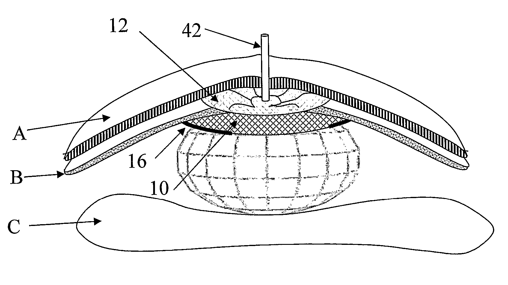
Reference is made now to FIGS. 2a and 2b, schematically illustrating lateral cross sections of the same, wherein mesh (10) is located between biological tissues B and C, and mesh (12) clasps between tissues (A) and (B). The hernia (9) between layers A and B is sealed by means of the novel two meshes infrastructure. It is acknowledged in this respect that the width and thickness of the biological tissues (A-C) and the hernia diameter may vary without significantly decreasing the effectiveness of the device (1). Either posterior or anterior meshes are flexible, and tolerate a wide scope of hernia systems, such as the case demonstrated in FIG. 2b.
Reference is made now to FIGS. 3a and 3d, schematically illustrating top view of the implantable means for treating hernia according to another embodiment of the present invention. Collar (16) is presented in various modes. The portion of mesh (10) which is not enveloped is determined by various parameters, such as mesh's flexibility, size etc. Collar (16) may be utilized as single thin member (FIG. 3a), layered member (FIG. 3b-c), double layered member (FIG. 3d) etc.
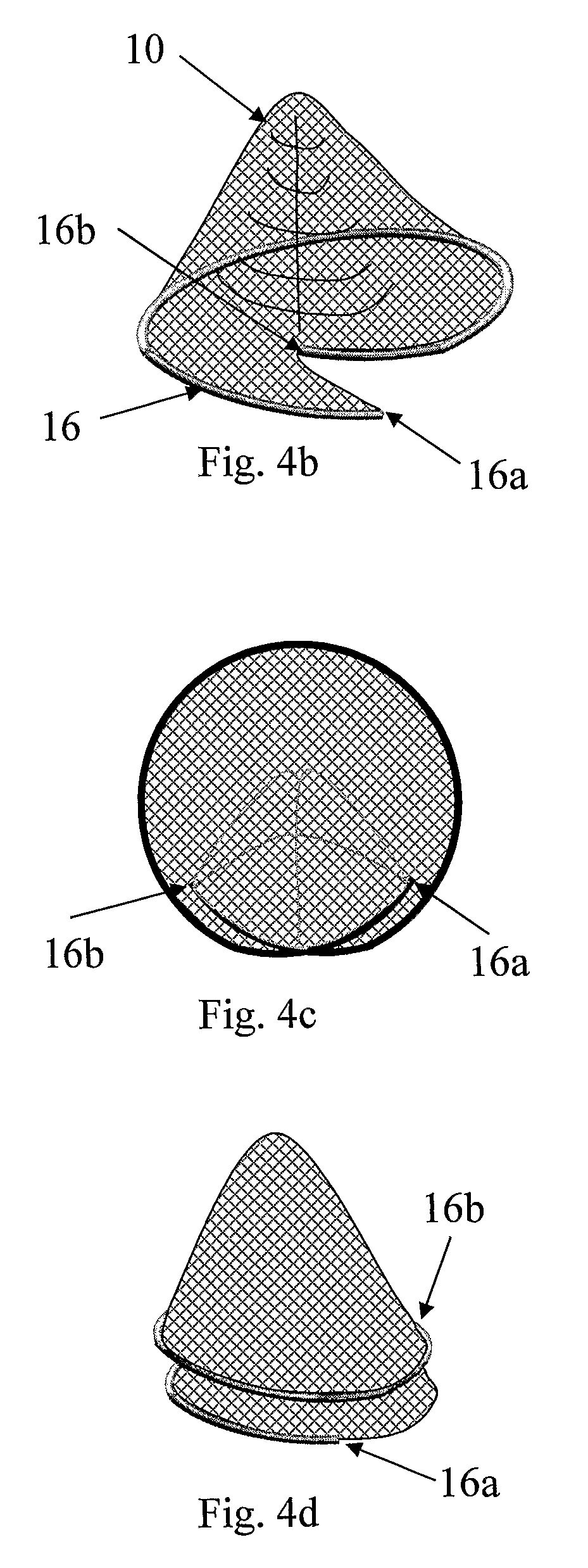
Reference is made now to FIGS. 4a to 4d, schematically illustrating perspective view of the implantable means for treating hernia according to another embodiment of the present invention, wherein collar (16) is rolled in a manner it deployed helically. Those examples are provided with few possible mechanisms to construct 3D cone-like mesh member from 2D flattened mesh. Various collapsing techniques are hence demonstrated, wherein other are also possible. FIG. 5 also presenting a schematic view of a helix-like rolled mesh, adapted to expend in a manner is perimeter is enlarged while it rotates, thus enabling the effective, smooth and rapid thrust of the mesh towards the posterior abdominal wall.
Reference is made now to FIGS. 6a and 6b, schematically illustrating a perspective view of the implantable means having two interconnected mesh layers according to another embodiment of the present invention. The posterior mesh (10) is loosely folded (FIG. 6a) such that flexible helix is directed to the posterior side of the hernia, wherein the anterior mesh (12) is folded in an opposite direction. Connection (14) interconnects the same. Right scheme, i.e., FIG. 6b presents the same in a helix-like tight rolling configuration such that the external diameter of the rolled mesh is significantly smaller than its diameter in its terminal open configuration.
Reference is made now to FIGS. 7a to 7c, schematically illustrating a perspective and lateral cross sections of sterilizeable implantable means comprising an elongated applicator (2) with an open bore, wherein two interconnected mesh layers are rolled according to another embodiment of the present invention. This syringe-like applicator is comprised of injecting means comprising a handle (3) adapted for one hand use (24) wherein the piston axle (22) penetrates the applicator-rounded envelope (20) via opening (26). Aperture 21 is especially provided for feeding fluids, chemicals, lubricants, glues, biocides etc into or onto the hernia. The two meshes may by assembled by a means of joint or connector (28).
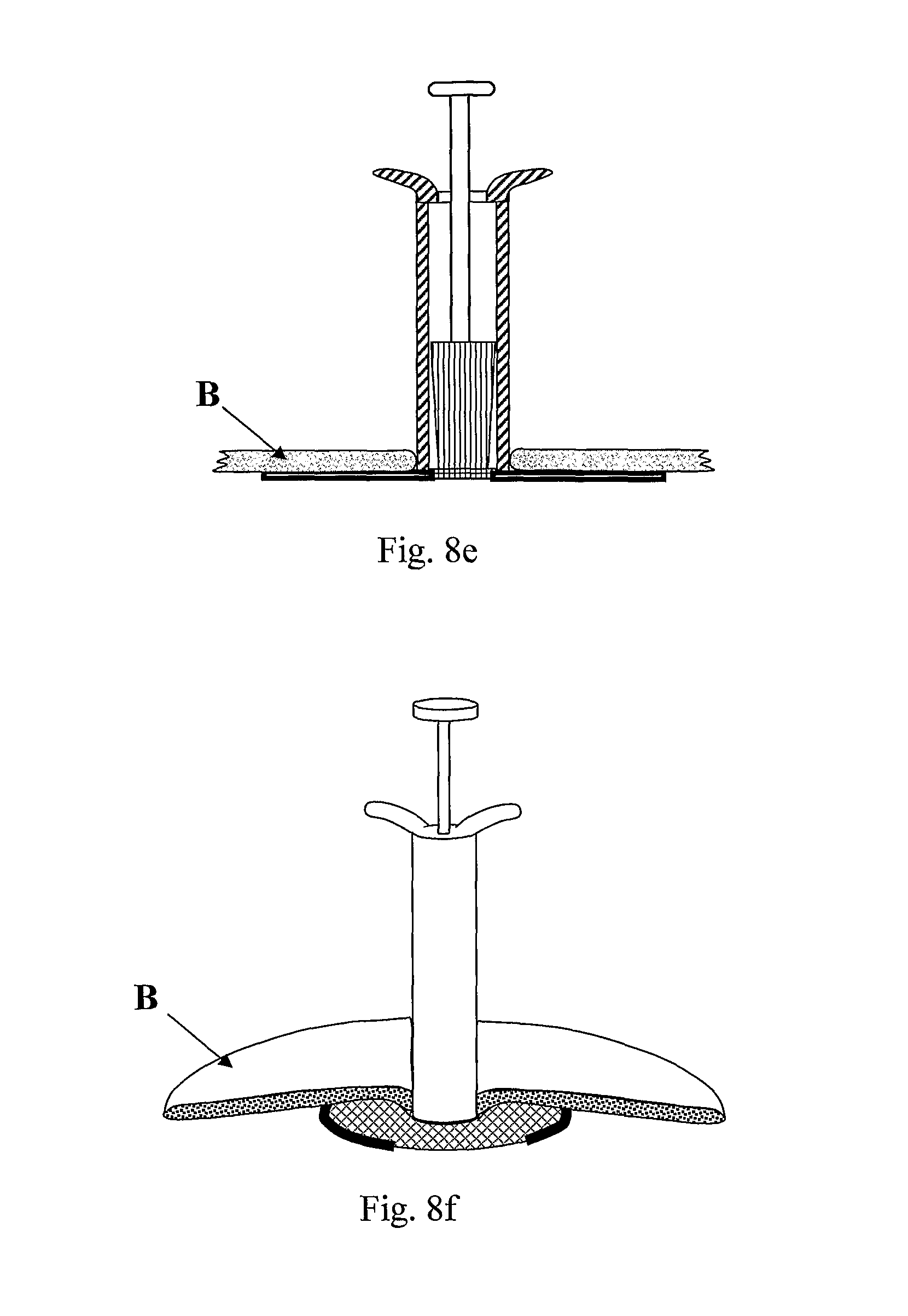
Reference is made now to FIGS. 8a and 8f, schematically illustrating a perspective view and lateral cross sections of a method of treating hernia by means of implantable applicator comprising two interconnected mesh layers according to another embodiment of the present invention. The applicator is initially inserted into the hernia (FIG. 8a) such that its posterior orifice is located between two predetermined tissues (A and C). The posterior mesh is helically deployed (FIGS. 8b-8f) such that it protruded in the body along the layers, and situated itself tightly between layers B and C.
Reference is made now to FIGS. 9a and 9c, schematically illustrating a perspective views of the implantable means according to another embodiment of the present invention. The role of the anterior mesh is hereby presented, wherein maneuvering the pistol of the applicator backwardly; the anterior mesh is ejected, lying parallel to the abdominal wall, sealing hermetically the hernia opening.
Reference is made now to FIGS. 10a and 10h schematically illustrating one method of utilizing a balloon as a driving force for helically deploying the posterior mesh according to another embodiment of the present invention. The balloon comprising an inflatable portion (40), fluid tubing (42) and a liquid anterior orifice (44). This method is comprising the step of applying at least one stripe (45), said stripe is immobilized to the balloon inner portion and loose free at the anterior end of the applicator (44), such that by pulling the stripe deflated balloon is ejected outside the applicator in a collapsed manner. The proportions of the two meshes (10, 12), collar (16) and balloon may widely vary; especially their external diameter may be of various ratios. Views 10e to 10g present one possible mode of the sealed connector, adapted to comprise inflation tube (42), by comprising overlapping wings of both upper and lower meshes. View 10h presents a perspective illustration of the same. The balloon is shown to provide an effective foundation and driving force for thrusting the posterior mesh forwardly.
Reference is made now to FIG. 11, schematically illustrating a perspective view of the implantable assembly according to another embodiment of the present invention. This assembly comprises the applicator (1-4) as defined in any of the above, a balloon inflating tubing (42), and inflating means comprising inter alia a syringe (5) and tubing connector (44).
Reference is made now to FIGS. 12a-12b, schematically illustrating a perspective views and a cross section of the implantable assembly according to another embodiment of the present invention. Those schemes present the folding-deployment mechanism of balloon 40 in respect to the helically rolled posterior mesh. The inner diameter of the pistol handle (3) and the inner diameter of balloon's inflating tubing 42 is adapted to be wide enough that the deflated balloon can be collapsed and ejected outside the applicator via the pistol handle.
Reference is made now to FIGS. 13a-13c, schematically illustrating lateral cross sections of the implantable assembly according to another embodiment of the present invention. Those schemes demonstrate the incorporated mechanism of the implant assembly, specifically presenting the inflation of the balloon and then the helical deployment of posterior mesh.
Reference is made now to FIGS. 14a to 14d, schematically illustrating cross sections of the implantable assembly according to another embodiment of the present invention. Those schemes show that after inflating the balloon and deploying the two meshes (10, 12), applicator (2, 3) is removed. This assembly thus comprise a non-return valve (44) retaining the inflating fluid inside the balloon and its tubing (42).
Reference is made now to FIGS. 15a to 15c, schematically illustrating fastening means (18, 19, 19a) e.g., nail-like, tooth-like, screw-like fasteners according to another embodiment of the present invention. Those fastening means are of various sizes, shapes and fastening mechanisms. Usually yet not exclusively the fastening means are located on the collar portion (16) of the device. Those fastening means may be directly or indirectly (19b) immobilize to the collar.
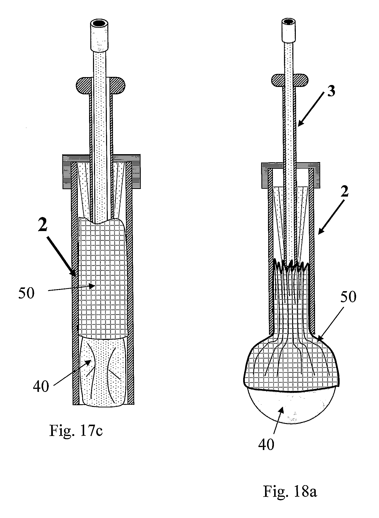
Reference is made now to FIGS. 16a to 16d, schematically illustrating coordinating sleeve (50) according to another embodiment of the present invention. Hence, for example, sleeve 40 is enveloping balloon 50 such that the steps deployment of mesh 10 and inflation of balloon 40 are coordinated at time. Reference is made to FIG. 17a to 17c, presenting the method of coordinating or sustaining either the deployment of mesh 10, and/or balloon 40 by means of sleeve 50 located in the applicator shall (2). Lastly, reference is made to FIGS. 18a to 18d showing the same method and coordinating/sustaining means and the various implementing process.
* * * * *
D00000
D00001
D00002
D00003
D00004
D00005
D00006
D00007
D00008
D00009
D00010
D00011
D00012

D00013

D00014

D00015

D00016

D00017

D00018

D00019

D00020

D00021

D00022

D00023

D00024
D00025

D00026

XML
uspto.report is an independent third-party trademark research tool that is not affiliated, endorsed, or sponsored by the United States Patent and Trademark Office (USPTO) or any other governmental organization. The information provided by uspto.report is based on publicly available data at the time of writing and is intended for informational purposes only.
While we strive to provide accurate and up-to-date information, we do not guarantee the accuracy, completeness, reliability, or suitability of the information displayed on this site. The use of this site is at your own risk. Any reliance you place on such information is therefore strictly at your own risk.
All official trademark data, including owner information, should be verified by visiting the official USPTO website at www.uspto.gov. This site is not intended to replace professional legal advice and should not be used as a substitute for consulting with a legal professional who is knowledgeable about trademark law.