Optical apparatus and augmented reality device
Lan , et al. April 19, 2
U.S. patent number 11,308,695 [Application Number 16/231,812] was granted by the patent office on 2022-04-19 for optical apparatus and augmented reality device. This patent grant is currently assigned to LENOVO (BEIJING) CO., LTD.. The grantee listed for this patent is Lenovo (Beijing) Co., Ltd.. Invention is credited to Shun Lan, Lu Tang, Zhou Zhang.


View All Diagrams
| United States Patent | 11,308,695 |
| Lan , et al. | April 19, 2022 |
Optical apparatus and augmented reality device
Abstract
An optical apparatus and an augmented reality device are provided. The optical apparatus includes an inner surface. The inner surface includes a predetermined region serving as a curved mirror with a predetermined optical parameter for reflection imaging of a virtual image of a virtual world. The optical apparatus further includes an outer surface. The outer surface and the inner surface are used for refraction imaging of a real image of a real world. The virtual image and the real image are integrated for forming a scene of augmented reality.
| Inventors: | Lan; Shun (Beijing, CN), Zhang; Zhou (Beijing, CN), Tang; Lu (Beijing, CN) | ||||||||||
|---|---|---|---|---|---|---|---|---|---|---|---|
| Applicant: |
|
||||||||||
| Assignee: | LENOVO (BEIJING) CO., LTD.
(Beijing, CN) |
||||||||||
| Family ID: | 61707444 | ||||||||||
| Appl. No.: | 16/231,812 | ||||||||||
| Filed: | December 24, 2018 |
Prior Publication Data
| Document Identifier | Publication Date | |
|---|---|---|
| US 20190197790 A1 | Jun 27, 2019 | |
Foreign Application Priority Data
| Dec 22, 2017 [CN] | 201711416355.9 | |||
| Current U.S. Class: | 1/1 |
| Current CPC Class: | G02B 27/0172 (20130101); G02B 27/14 (20130101); G06T 19/006 (20130101); G02B 2027/0178 (20130101); G02B 2027/013 (20130101); G02B 2027/011 (20130101) |
| Current International Class: | G06T 19/00 (20110101); G02B 27/01 (20060101); G02B 27/14 (20060101) |
References Cited [Referenced By]
U.S. Patent Documents
| 4881801 | November 1989 | Gebelein |
| 5404246 | April 1995 | Kaneko |
| 5517366 | May 1996 | Togino |
| 5644436 | July 1997 | Togino |
| 5661604 | August 1997 | Kuba |
| 5691850 | November 1997 | Arisaka |
| 5745295 | April 1998 | Takahashi |
| 5754344 | May 1998 | Fujiyama |
| 5926321 | July 1999 | Shikama |
| 5966242 | October 1999 | Yamanaka |
| 5986816 | November 1999 | Shikama |
| 6094242 | July 2000 | Yamanaka |
| 6094309 | July 2000 | Ophey |
| 6201647 | March 2001 | Ohzawa |
| 6246383 | June 2001 | Ophey |
| 6417820 | July 2002 | Choi |
| 6519090 | February 2003 | Endo |
| 6813085 | November 2004 | Richards |
| 6999239 | February 2006 | Martins |
| 7095570 | August 2006 | Amanai |
| 7545571 | June 2009 | Garoutte |
| 7602552 | October 2009 | Blumenfeld |
| 7667783 | February 2010 | Hong |
| 8189272 | May 2012 | Huang |
| 8582209 | November 2013 | Amirparviz |
| 9316816 | April 2016 | Noda |
| 9350908 | May 2016 | Hsu |
| 9395525 | July 2016 | Matsumoto |
| 9578423 | February 2017 | Liu |
| 9690324 | June 2017 | Liu |
| 9720227 | August 2017 | Border |
| 9720232 | August 2017 | Hua |
| 9804364 | October 2017 | Sekine |
| 9810908 | November 2017 | Tanahashi |
| 9841598 | December 2017 | Ouderkirk |
| 9854196 | December 2017 | Liu |
| 9874760 | January 2018 | Hua |
| 9910284 | March 2018 | Nortrup |
| 9939646 | April 2018 | Osterhout |
| 9939648 | April 2018 | Lee |
| 9952435 | April 2018 | Tanaka |
| 9954613 | April 2018 | Goorjian |
| 10042157 | August 2018 | Matsuo |
| 10120194 | November 2018 | Cobb |
| 10129984 | November 2018 | Lamkin |
| 10175487 | January 2019 | Benko |
| 10175785 | January 2019 | Liu |
| 10191279 | January 2019 | Nortrup |
| 10197810 | February 2019 | Seo |
| 10234604 | March 2019 | Huang |
| 10277893 | April 2019 | Yoon |
| 10281729 | May 2019 | Kuo |
| 10318226 | June 2019 | Zhang |
| 10326983 | June 2019 | Hua |
| 10371998 | August 2019 | Sahlsten |
| 10422995 | September 2019 | Haddick |
| 10427598 | October 2019 | Yamagata |
| 10466481 | November 2019 | Li |
| 10466491 | November 2019 | Osterhout |
| 10473926 | November 2019 | Lee |
| 10495888 | December 2019 | Yonekubo |
| 10510812 | December 2019 | Lamkin |
| 10520734 | December 2019 | Chan |
| 10527819 | January 2020 | Bone |
| 10527859 | January 2020 | Tanaka |
| 10534172 | January 2020 | Tanaka |
| 10545347 | January 2020 | Bierhuizen |
| 10564427 | February 2020 | Ouderkirk |
| 10567745 | February 2020 | Patel |
| 10591707 | March 2020 | Khan |
| 10594951 | March 2020 | Lamkin |
| 10600352 | March 2020 | Wheelwright |
| 10613320 | April 2020 | Masson |
| 10642044 | May 2020 | Ouderkirk |
| 10652529 | May 2020 | Lamkin |
| 10663626 | May 2020 | Benitez |
| 10663724 | May 2020 | Laduke |
| 10663736 | May 2020 | Tanaka |
| 10816752 | October 2020 | Wang |
| 10816766 | October 2020 | Fang |
| 10816767 | October 2020 | Fang |
| 10881287 | January 2021 | Ouderkirk |
| 10890695 | January 2021 | Piskunov |
| 10901291 | January 2021 | Sulai |
| 10948801 | March 2021 | Lu |
| 10955675 | March 2021 | Wheelwright |
| 10962791 | March 2021 | Ouderkirk |
| 10962795 | March 2021 | Gollier |
| 10976551 | April 2021 | Cobb |
| 2002/0024743 | February 2002 | Endo |
| 2002/0057498 | May 2002 | Kobayashi |
| 2002/0131168 | September 2002 | Sadler |
| 2003/0089691 | May 2003 | Tanaka |
| 2003/0107816 | June 2003 | Takagi |
| 2003/0184868 | October 2003 | Geist |
| 2004/0160680 | August 2004 | Shinohara |
| 2004/0227703 | November 2004 | Lamvik |
| 2005/0117497 | June 2005 | Komma |
| 2006/0072205 | April 2006 | Li |
| 2006/0098293 | May 2006 | Garoutte |
| 2007/0070508 | March 2007 | Ruhle |
| 2008/0013185 | January 2008 | Garoutte |
| 2008/0106489 | May 2008 | Brown |
| 2008/0117289 | May 2008 | Schowengerdt |
| 2009/0147126 | June 2009 | Miyoshi |
| 2009/0147331 | June 2009 | Ashkenazi |
| 2009/0161225 | June 2009 | Liu |
| 2010/0060551 | March 2010 | Sugiyama |
| 2010/0097710 | April 2010 | Lai |
| 2010/0220399 | September 2010 | Ohtake |
| 2010/0321788 | December 2010 | Wang |
| 2011/0102874 | May 2011 | Sugiyama |
| 2011/0292333 | December 2011 | Kozaki |
| 2011/0292513 | December 2011 | Kubota |
| 2012/0002295 | January 2012 | Dobschal |
| 2012/0105310 | May 2012 | Sverdrup |
| 2012/0154536 | June 2012 | Stoker |
| 2012/0162486 | June 2012 | Asakura |
| 2012/0162549 | June 2012 | Gao |
| 2012/0293874 | November 2012 | Matsui |
| 2012/0300318 | November 2012 | Lin |
| 2013/0021226 | January 2013 | Bell |
| 2013/0135754 | May 2013 | Ise |
| 2013/0169931 | July 2013 | Lee |
| 2013/0258164 | October 2013 | Chang |
| 2013/0278714 | October 2013 | Hirose |
| 2014/0146394 | May 2014 | Tout |
| 2014/0160338 | June 2014 | Kikuchi |
| 2014/0218806 | August 2014 | Ishizuka |
| 2014/0266986 | September 2014 | Magyari |
| 2014/0266990 | September 2014 | Makino |
| 2014/0307335 | October 2014 | Kawamura |
| 2014/0361957 | December 2014 | Hua |
| 2015/0022901 | January 2015 | Komatsu |
| 2015/0049004 | February 2015 | Deering |
| 2015/0070389 | March 2015 | Goto |
| 2015/0070773 | March 2015 | Wang |
| 2015/0103152 | April 2015 | Qin |
| 2015/0103412 | April 2015 | Ori |
| 2015/0138047 | May 2015 | Hwang |
| 2015/0168730 | June 2015 | Ashkenazi |
| 2015/0177906 | June 2015 | Yairi |
| 2015/0185828 | July 2015 | Wu |
| 2015/0192775 | July 2015 | Suzuki |
| 2015/0219898 | August 2015 | Ko |
| 2015/0234477 | August 2015 | Abovitz |
| 2015/0253543 | September 2015 | Mercado |
| 2015/0253575 | September 2015 | Huang |
| 2015/0253647 | September 2015 | Mercado |
| 2015/0279114 | October 2015 | Yonekubo |
| 2015/0370074 | December 2015 | McDowall |
| 2016/0011404 | January 2016 | Suzuki |
| 2016/0077319 | March 2016 | Yatsu |
| 2016/0085084 | March 2016 | Masson |
| 2016/0091722 | March 2016 | Liu |
| 2016/0097929 | April 2016 | Yee |
| 2016/0124192 | May 2016 | Koreeda |
| 2016/0139363 | May 2016 | Hsu |
| 2016/0154216 | June 2016 | Liao |
| 2016/0161718 | June 2016 | Koreeda |
| 2016/0170208 | June 2016 | Border |
| 2016/0198949 | July 2016 | Spitzer |
| 2016/0209624 | July 2016 | Usui |
| 2016/0209652 | July 2016 | Ichihashi |
| 2016/0216483 | July 2016 | Chen |
| 2016/0216484 | July 2016 | Chen |
| 2016/0223819 | August 2016 | Liu |
| 2016/0241754 | August 2016 | Jhang |
| 2016/0261780 | September 2016 | Lin |
| 2016/0278695 | September 2016 | Wang |
| 2016/0291325 | October 2016 | Kasahara |
| 2016/0291326 | October 2016 | Evans |
| 2016/0314564 | October 2016 | Jones |
| 2016/0320619 | November 2016 | Watanabe |
| 2016/0327793 | November 2016 | Chen |
| 2016/0356987 | December 2016 | Liu |
| 2017/0045742 | February 2017 | Greenhalgh |
| 2017/0068095 | March 2017 | Holland |
| 2017/0123187 | May 2017 | Heu |
| 2017/0193687 | July 2017 | Lo |
| 2017/0219799 | August 2017 | Hsueh |
| 2017/0255015 | September 2017 | Geng |
| 2017/0269366 | September 2017 | Lee |
| 2017/0285343 | October 2017 | Belenkii |
| 2017/0311794 | November 2017 | Inoue |
| 2017/0315343 | November 2017 | Nagler |
| 2017/0315347 | November 2017 | Juhola |
| 2017/0343822 | November 2017 | Border |
| 2017/0357088 | December 2017 | Matsuzaki |
| 2017/0357100 | December 2017 | Ouderkirk |
| 2017/0371163 | December 2017 | Ries |
| 2018/0003978 | January 2018 | Benitez |
| 2018/0017795 | January 2018 | Li |
| 2018/0024355 | January 2018 | Gao |
| 2018/0039052 | February 2018 | Khan |
| 2018/0039061 | February 2018 | Hairston |
| 2018/0045916 | February 2018 | Chang |
| 2018/0067317 | March 2018 | Barton |
| 2018/0081151 | March 2018 | Bone |
| 2018/0107000 | April 2018 | Sung |
| 2018/0120568 | May 2018 | Miller |
| 2018/0143401 | May 2018 | Bone |
| 2018/0146188 | May 2018 | Simmonds |
| 2018/0157320 | June 2018 | Trail |
| 2018/0196231 | July 2018 | Bone |
| 2018/0196264 | July 2018 | Quere |
| 2018/0196265 | July 2018 | Bouchier |
| 2018/0203205 | July 2018 | Cao |
| 2018/0203505 | July 2018 | Trail |
| 2018/0210181 | July 2018 | Kim |
| 2018/0239117 | August 2018 | Lee |
| 2018/0275394 | September 2018 | Yeoh |
| 2018/0275408 | September 2018 | Deng |
| 2018/0284454 | October 2018 | Reed |
| 2018/0307036 | October 2018 | Iba |
| 2018/0341110 | November 2018 | Hirata |
| 2019/0004325 | January 2019 | Connor |
| 2019/0018235 | January 2019 | Ouderkirk |
| 2019/0025475 | January 2019 | Piskunov |
| 2019/0025688 | January 2019 | Maynard |
| 2019/0026871 | January 2019 | Han |
| 2019/0049733 | February 2019 | Jiang |
| 2019/0064485 | February 2019 | Arita |
| 2019/0064526 | February 2019 | Connor |
| 2019/0064527 | February 2019 | Kuo |
| 2019/0086662 | March 2019 | Matsuzaki |
| 2019/0086675 | March 2019 | Carollo |
| 2019/0094486 | March 2019 | Wang |
| 2019/0094981 | March 2019 | Bradski |
| 2019/0114950 | April 2019 | Calm |
| 2019/0146198 | May 2019 | Khan |
| 2019/0171005 | June 2019 | Lee |
| 2019/0179409 | June 2019 | Jones |
| 2019/0183340 | June 2019 | Mo |
| 2019/0191991 | June 2019 | Nozawa |
| 2019/0197790 | June 2019 | Lan |
| 2019/0227322 | July 2019 | Schaub |
| 2019/0227331 | July 2019 | Roessel |
| 2019/0235196 | August 2019 | Hong |
| 2019/0265440 | August 2019 | Tabata |
| 2019/0265493 | August 2019 | Takagi |
| 2019/0265494 | August 2019 | Takagi |
| 2019/0293938 | September 2019 | Le Saux |
| 2019/0302437 | October 2019 | Hillman |
| 2019/0310705 | October 2019 | Hincapie Ramos |
| 2019/0331919 | October 2019 | Huo |
| 2019/0339518 | November 2019 | Zanden |
| 2019/0346679 | November 2019 | Miller |
| 2019/0384068 | December 2019 | Park |
| 2020/0033586 | January 2020 | Suzuki |
| 2020/0033607 | January 2020 | Takeda |
| 2020/0041785 | February 2020 | Takagi |
| 2020/0049800 | February 2020 | Valouch |
| 2020/0049956 | February 2020 | Chan |
| 2020/0081234 | March 2020 | Etter |
| 2020/0089017 | March 2020 | Wu |
| 2020/0096772 | March 2020 | Adema |
| 2020/0096816 | March 2020 | Lee |
| 2020/0124853 | April 2020 | Lo |
| 2020/0132988 | April 2020 | Smithwick |
| 2020/0142254 | May 2020 | Ryu |
| 2020/0143524 | May 2020 | Selstad |
| 2020/0150405 | May 2020 | Bates |
| 2020/0151956 | May 2020 | Goslin |
| 2020/0180069 | June 2020 | Sangu |
| 2020/0183079 | June 2020 | Leister |
| 2020/0192079 | June 2020 | Tohara |
| 2020/0192096 | June 2020 | Chen |
| 2020/0201047 | June 2020 | Nakamura |
| 2020/0225477 | July 2020 | Chan |
| 2020/0249475 | August 2020 | Amirsolaimani |
| 2020/0264441 | August 2020 | Lee |
| 2020/0319430 | October 2020 | Hosono |
| 2020/0319456 | October 2020 | Yatsu |
| 2020/0326543 | October 2020 | Kim |
| 2020/0341268 | October 2020 | Amirsolaimani |
| 2020/0341278 | October 2020 | Tanaka |
| 2020/0341315 | October 2020 | Gollier |
| 2020/0348528 | November 2020 | Jamali |
| 2020/0379214 | December 2020 | Lee |
| 2020/0409034 | December 2020 | Kuo |
| 2020/0409037 | December 2020 | Kuo |
| 2021/0018955 | January 2021 | Ciou |
| 2021/0033865 | February 2021 | Smith |
| 2021/0033868 | February 2021 | Inoguchi |
| 2021/0088782 | March 2021 | Zhao |
| 2021/0109352 | April 2021 | Lee |
| 2021/0132267 | May 2021 | Hernandez |
| 2021/0132342 | May 2021 | Kim |
| 2021/0132388 | May 2021 | Yamaguchi |
| 2021/0209364 | July 2021 | Park |
| 2021/0223551 | July 2021 | Zannoli |
| 2021/0227187 | July 2021 | Stanley |
| 2021/0258555 | August 2021 | Lei |
| 2021/0271055 | September 2021 | Kuo |
| 2021/0271087 | September 2021 | Jung |
| 2021/0294117 | September 2021 | Mizuta |
| 2021/0334943 | October 2021 | Chu |
| 2021/0358084 | November 2021 | Bleyer |
| 2021/0364799 | November 2021 | Guo |
| 2021/0364802 | November 2021 | Uchiyama |
| 2021/0373336 | December 2021 | Price |
| 101359089 | Feb 2009 | CN | |||
| 203786390 | Aug 2014 | CN | |||
| 104749779 | Jul 2015 | CN | |||
| 104903777 | Sep 2015 | CN | |||
| 105892058 | Aug 2016 | CN | |||
| 107247334 | Oct 2017 | CN | |||
Other References
|
Yan Lou, "Basic application of computer and information technology", Tsinghua university press, Jul. 31, 2016 (Jul. 31, 2016), p. 90-91 6 Pages (including translation). cited by applicant. |
Primary Examiner: Beard; Charles L
Attorney, Agent or Firm: Anova Law Group, PLLC
Claims
What is claimed is:
1. An optical apparatus for a wearable augmented reality device, comprising: an inner surface, the inner surface being an irregular and aspherical surface and a surface of the optical apparatus that directly faces the user, wherein the inner surface comprises a predetermined region serving as a curved mirror with a predetermined optical parameter for reflection imaging of a virtual image of a virtual world; and an outer surface, the outer surface being an irregular and aspherical surface, wherein: an axis of the optical apparatus is parallel to a direction of observing the virtual world, the axis of the optical apparatus intersecting with the inner surface region serving as the curved mirror; the inner surface and the outer surface are used for refraction imaging of a real image of a real world, and the virtual image and the real image are integrated for forming a scene of augmented reality; a thickness between the inner surface and the outer surface is uneven; the predetermined region of the inner surface comprises an upper half portion of the inner surface and a lower half portion of the inner surface, one of the upper half portion of the inner surface and the lower half portion of the inner surface having a concave shape until the other one having a convex shape; and the outer surface comprises an upper half portion of the outer surface and a lower half portion of the outer surface, one of the upper half portion of the outer surface and the lower half portion of the outer surface having a concave shape until the other one having a convex shape, such that lens comprising the inner surface and the outer surface eliminate distortion for a user of the wearable augmented reality device and the user observes the scene of augmented reality at a focal point of the lens.
2. The apparatus according to claim 1, wherein: the inner surface comprises at least two predetermined regions serving as curved mirrors integrated into the inner surface to eliminate distortion due to differences of the virtual image viewed by a left eye and a right eye of the user; and the predetermined optical parameter comprises values of curvature radius, thickness and size that matches a corresponding parameter suitable for the curved mirrors for the wearable augmented reality device.
3. An augmented reality device, comprising: a memory and a processor for executing instructions stored in the memory; a display screen; and an optical apparatus; wherein: when the instructions are executed by the processor, the processor cause the display screen to provide a virtual image of a virtual world to the optical apparatus; and the optical apparatus comprises: an inner surface, the inner surface being an irregular and aspherical surface and a surface of the optical apparatus that directly faces a user of the augmented reality device, and the inner surface having a predetermined region serving as a curved mirror with a predetermined optical parameter for reflection imaging of the virtual image of the virtual world; and an outer surface, the outer surface being an irregular and aspherical surface, wherein: an axis of the optical apparatus is parallel to a direction of observing the virtual world, the axis of the optical apparatus intersecting with the inner surface region serving as the curved mirror; the inner surface and the outer surface are used for refraction imaging of a real image of a real world, and the virtual image and the real image are integrated for forming a scene of augmented reality; a thickness between the inner surface and the outer surface is uneven; the predetermined region of the inner surface comprises an upper half portion of the inner surface and a lower half portion of the inner surface, one of the upper half portion of the inner surface and the lower half portion of the inner surface having a concave shape until the other one having a convex shape; and the outer surface comprises an upper half portion of the outer surface and a lower half portion of the outer surface, one of the upper half portion of the outer surface and the lower half portion of the outer surface having a concave shape until the other one having a convex shape, such that lens comprising the inner surface and the outer surface eliminate distortion for a user of the wearable augmented reality device and the user observes the scene of augmented reality at a focal point of the lens.
4. The device according to claim 3, further comprising: a beam splitter, for receiving the virtual image projected from the display screen and reflecting the virtual image to the predetermined region of the inner surface of the optical apparatus.
5. The device according to claim 4, wherein the beam splitter and the optical apparatus form a coaxial optical system.
6. The device according to claim 4, wherein the processor is further configured to: cause an adjusting device disposed inside the augmented reality device to adjust a relative position between the inner surface of the optical apparatus and the beam splitter to be a predetermined relative position.
7. The device according to claim 3, wherein the processor is further configured to: cause a positioning device to obtain position information of the augmented reality device to adjust a relevant parameter of the virtual image projected from the display screen based on the position information.
8. The device according to claim 3, wherein: the inner surface comprises at least two predetermined regions serving as curved mirrors integrated into the inner surface to eliminate distortion due to differences of the virtual image viewed by a left eye and a right eye of the user; and the predetermined optical parameter comprises values of curvature radius, thickness and size that matches a corresponding parameter suitable for curved mirrors in the augmented reality device.
Description
CROSS-REFERENCES TO RELATED APPLICATIONS
This application claims priority of Chinese Patent Application No. 201711416355.9, filed on Dec. 22, 2017, the entire contents of which are hereby incorporated by reference.
FIELD OF THE DISCLOSURE
The present disclosure relates to an optical apparatus and an augmented reality device.
BACKGROUND
Augmented reality (AR) technology (also known as mixed reality technology) is a technology that uses computer technology to apply virtual information onto the real world, having the virtual objects and real environment superimposed into the same space. A user can experience the combined virtual reality and real world scene using the augmented reality device. For example, the user can experience a combined virtual reality and real world scenes using electronic devices including wearable helmets, wearable glasses, and the like.
BRIEF SUMMARY OF THE DISCLOSURE
One aspect of the present disclosure provides an optical apparatus. The optical apparatus includes an inner surface. The inner surface includes a predetermined region serving as a curved mirror with a predetermined optical parameter for reflection imaging of a virtual image of a virtual world. The optical apparatus further includes an outer surface. The outer surface and the inner surface are used for refraction imaging of a real image of a real world. The virtual image and the real image are integrated for forming a scene of augmented reality.
Another aspect of the present disclosure provides an augmented reality device. The augmented reality device includes an image providing device for providing a virtual image of a virtual world and an optical apparatus. The optical apparatus includes an inner surface. The inner surface includes a predetermined region serving as a curved mirror with a predetermined optical parameter for reflection imaging of the virtual image of the virtual world. The optical apparatus further includes an outer surface. The outer surface and the inner surface are used for refraction imaging of a real image of a real world. The virtual image and the real image are integrated for forming a scene of augmented reality.
Other aspects of the present disclosure can be understood by those skilled in the art in light of the description, the claims, and the drawings of the present disclosure.
BRIEF DESCRIPTION OF THE DRAWINGS
The following drawings are merely examples for illustrative purposes according to various disclosed embodiments and are not intended to limit the scope of the present disclosure.
FIG. 1A illustrates an application scenario of an augmented reality device and an optical apparatus according to some embodiments of the present disclosure;
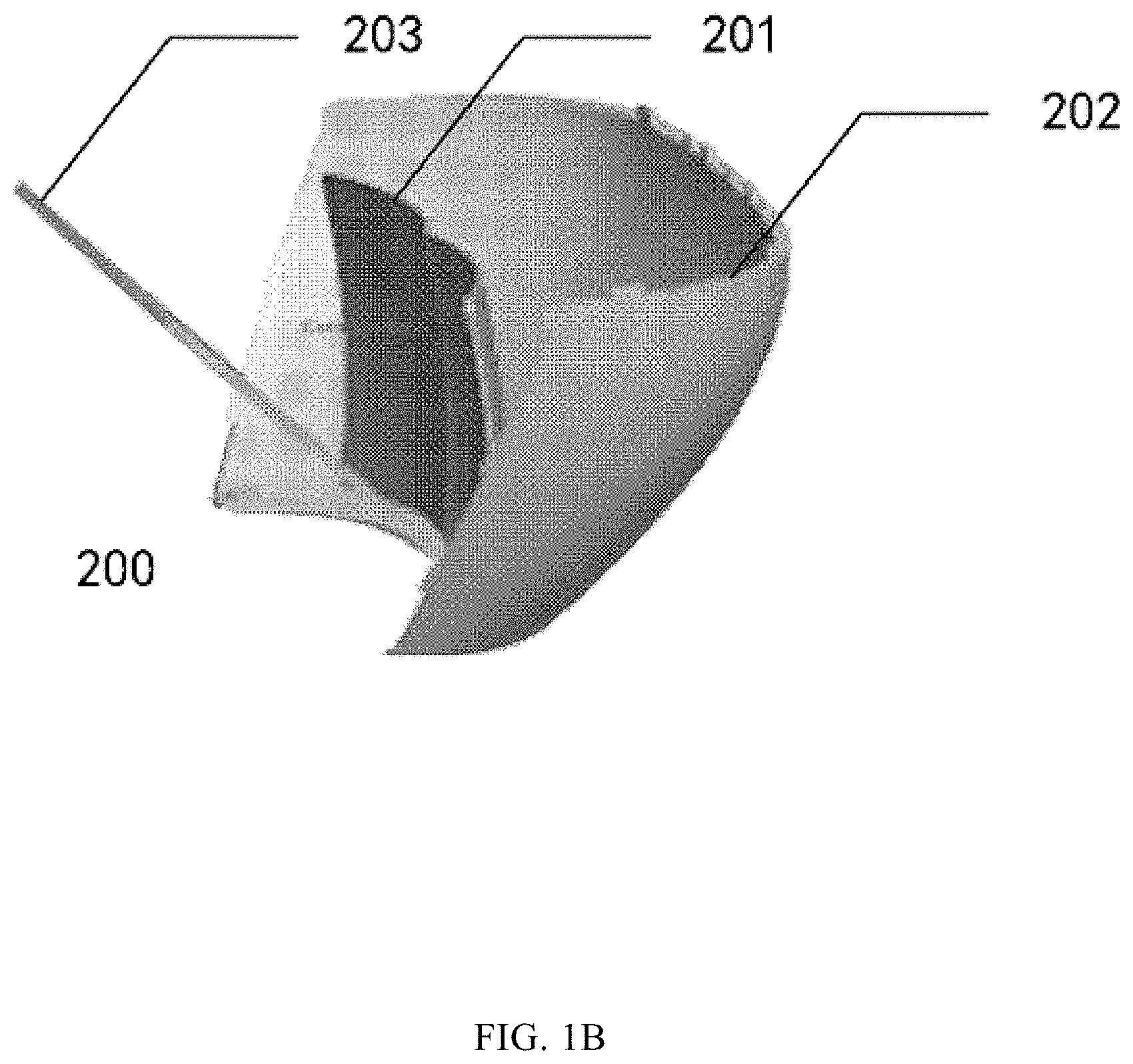
FIG. 1B illustrates a schematic diagram of an augmented reality device with a curved mirror;
FIG. 1C illustrates a schematic diagram of an augmented reality device according to some embodiments of the present disclosure;
FIG. 1D illustrates a schematic diagram of a curved mirror structure of an augmented reality device;
FIG. 1E illustrates a schematic view of a curved mirror structure of an augmented reality device according to some embodiments of the present disclosure;
FIG. 2A illustrates a schematic diagram of virtual image formation of an augmented reality device according to some embodiments of the present disclosure;
FIG. 2B illustrates a schematic diagram of image formation of a real image in an augmented reality device according to some embodiments of the present disclosure;
FIG. 3A illustrates a schematic view of an off-axis design of an optical system according to v of the present disclosure;
FIG. 3B illustrates a schematic view of a coaxial design of an optical system according to some embodiments of the present disclosure;
FIG. 4 illustrates a block diagram of another augmented reality device according to some embodiments of the present disclosure;
FIG. 5A illustrates a schematic view of irregular twisting of light of a real image through an optical apparatus;
FIG. 5B illustrates a schematic diagram of forming a real image in an augmented reality device according to some embodiments of the present disclosure; and
FIG. 6 illustrates a block diagram of another augmented reality device according to some embodiments of the present disclosure.
DETAILED DESCRIPTION
Embodiments of the present disclosure with reference to the accompanying drawings are described below. It should be understood, however, that these descriptions are merely illustrative and are not intended to limit the scope of the present disclosure. In addition, in the following description, descriptions of well-known structures and techniques are omitted so as not to obscure the concept of the present disclosure.
Terms used herein are only for describing embodiments only but not intended to limit the present disclosure. The terms "including", "comprising", and the like, as used herein, indicate the presence of stated features, steps, operations, and/or components, but do not exclude the presence or addition of one or more other features, steps, operations, or components.
Unless otherwise defined, all the technical and scientific terms used herein have the same or similar meanings as generally understood by those skilled in the art. It should be noted that terms used herein should be interpreted as having meanings that are consistent with the context of the present specification and should not be interpreted in an idealized or overly rigid manner.
In terms of a statement such as "at least one of A, B, and C, etc.," it should be generally interpreted in light of the ordinary understanding of the expression by those skilled in the art. For example, "a system including at least one of A, B, and C" shall include, but is not limited to, a system including A alone, a system including B alone, a system including C alone, a system including A and B, a system including A and C, a system including B and C, and/or a system including A, B, and C, etc. In terms of a statement similar to "at least one of A, B or C, etc.", it should generally be interpreted in light of the ordinary understanding of the expression by those skilled in the art. For example, "a system including at least one of A, B or C" shall include, but is not limited to, a system including A alone, a system including B alone, a system including C alone, a system including A and B, a system including A and C, a system including B and C, and/or a system including A, B, and C, etc. It should also be understood by those skilled in the art that all transitional words and/or phrases representing two or more alternative items, whether in the description, the claims or the drawings, should be understood as including one of these alternative items, or including any one of or all these alternative items. For example, the phrase "A or B" should be interpreted to include possibilities of including "A" or "B", or including "A" and "B".
A number of block diagrams and/or flowcharts are shown in the drawings. It should be understood that some blocks and/or flows or combinations thereof in the block diagrams and/or the flowcharts can be implemented by computer program instructions. These computer program instructions may be provided to a processor of a general-purpose computer, a special-purpose computer, or other programmable-data processing device such that, when executed by the processor, these instructions may be configured to generate a device that can implement functions/operations illustrated in these block diagrams and/or flowcharts.
Thus, embodiments of the present disclosure may be implemented in the form of hardware and/or software (including firmware, microcode, etc.). In addition, embodiments of the present disclosure may in a form of a computer program product on a computer-readable medium that stores instructions. The computer program product can be used by or in connection with a program instruction execution system. In the context of the present disclosure, a computer-readable medium may be any medium that can contain, store, communicate, propagate, or transport the program instructions. For example, the computer-readable medium may include, but is not limited to, an electronic, magnetic, optical, electromagnetic, infrared or semiconductor system, apparatus, device, or propagation medium. Optionally, examples of the computer-readable medium may include: a magnetic storage device such as a magnetic tape or a hard disk (HDD); an optical storage device such as a compact disk read-only memory (CD-ROM); a memory such as a random-access memory (RAM) or a flash memory; and/or a cable/wireless communication link.
Various embodiments of the present disclosure provides an optical apparatus to integrate images of the virtual world with the real world. The optical apparatus includes an inner surface and an outer surface. The inner surface includes a predetermined region, and the predetermined region serves as a curved mirror with predetermined optical parameters to perform reflection imaging of the virtual world. The outer surface and the inner surface can be used for refraction imaging of the real world.
Embodiments of the present disclosure also provide an augmented reality device that includes at least the optical apparatus and an image providing device for providing virtual images of the virtual world.
FIG. 1A illustrates an application scenario for using an augmented reality device and an optical apparatus according to some embodiments of the present disclosure. It should be noted that FIG. 1A only illustrates some examples for better understanding the technical content of the present disclosure, although one of ordinary skill in the art would know that any suitable devices, systems, environments, or scenarios may be encompassed herein according to various embodiments of the present disclosure.
As shown in FIG. 1A, one application scenario includes an augmented reality device 100. The augmented reality device 100 includes an optical apparatus described in the present disclosure and a virtual object, e.g., a small red flag 102, can be virtualized by the augmented reality device 100, while the application scenario also includes a real object, e.g., a desk 101. The virtual object (e.g., small red flag 102) is inserted into the real object (e.g., desk 101). The user can observe the real object (e.g., desk 101) having the virtual object (e.g., small red flag 102) inserted into the real object (e.g., desk 101) by using the augmented reality device 100.
In another embodiment, the augmented reality device 100 projects light to render a virtual object (e.g., small red flag 102) onto the inner surface of the optical apparatus and then reflected into the user's eyes, while light of a real object in the real world (e.g., desk 101) reflects directly from, e.g., the desk 101, through the outer surface of the optical apparatus, penetrates the inner surface, and then projects into the user's eyes. In this case, the augmented reality device 100 can reflect the light of a virtual object to the user's eyes through the optical apparatus, and does not need to add a curved mirror to the augmented reality device 100 to reflect the light from the virtual object to the user's eyes.
FIG. 1B illustrates the schematic diagram of an augmented reality device with a curved mirror. As shown in FIG. 1B, the augmented reality device 200 includes a curved mirror 201, an optical apparatus 202 and a beam splitter 203. The augmented reality device 200 uses the curved mirror 201 to reflect the light to render the virtual object into the user's eye.
FIG. 1C illustrates the schematic diagram of an augmented reality device according to some embodiments of the present disclosure. As shown in FIG. 1C, the augmented reality device 300 may include a beam splitter 301 and an optical apparatus 302. The augmented reality device 300 reflects light of a virtual object to the user's eyes through the optical apparatus 302 without a need to use a curved mirror into the augmented reality device 300.
As disclosed, the disclosed optical apparatus and augmented reality device may eliminate the need to install the curved mirror, providing more compact apparatus/device with less materials.
As the light of real scene and virtual scene passing through the curved mirror in the relevant technology, there will be some loss of light. In embodiments of the present disclosure, lights pass through the inner surface and the outer surface of the optical apparatus, and then project into the eyes of the user, which reduces light loss in the optical path of the real scene image and virtual scene image.
FIG. 1D illustrates the schematic diagram of the curved mirror structure of an augmented reality device in the relevant technology. As shown in FIG. 1D, the two mirrors, 2011 and 2012, are separately arranged. Assembling the two curved surface mirrors 2011 and 2012 requires a high precision assembling process that has some shortcomings:
1. Since the two curved mirrors are molded separately, the faces of different batches of curved surfaces are difficult to be made consistently in different batches (due to manufacturing tolerances). The bias and tilt errors of curved mirrors are difficult to keep consistent in different batches, so the assembly accuracy is difficult to control.
2. Since the two curved mirrors are assembled separately, stresses exerted on each mirror during the assembly process are different. After the assembly, the curvatures of the two curved surface mirrors may vary with different degrees of deformation so the observed images of the left and right eyes may appear obvious differences.
As disclosed, functions of two curved mirrors are integrated into the inner surface of the optical apparatus so that the inner surface of the optical apparatus is functionally equivalent to the two curved mirrors, without including two curved mirrors. FIG. 1E illustrates the schematic diagram of the curved surface structure of an augmented reality device according to various embodiments of the present disclosure. As shown in FIG. 1E, the functions of the two curved mirrors are integrated into the inner surface of the optical apparatus, so that the values of curvature radius, thickness, size and other parameters of the corresponding region of the inner surface are designed to be the same or approximate to the parameters of the curved mirrors of the augmented reality device in the relevant technology.
The inner surface of the disclosed optical apparatus can serve as a curved mirror, and conventional curved mirrors of the augmented reality device can be removed from the disclosed augmented reality device. The disclosed optical apparatus can be integrated into an injection molding process, which eliminate installation of the mirrors. The virtual image viewed by the left and right eyes of a user does not have obvious differences.
In various embodiments, the augmented reality device can be a helmet, or a pair of glasses, although any suitable product forms, shapes and appearances may be used for the disclosed augmented reality device.
As such, the augmented reality device may integrate the virtual world with the real world, and may include an optical apparatus. The optical apparatus includes an inner surface and an outer surface. The inner surface includes a predetermined region, and the predetermined region provides the functions as of a curved mirror with a predetermined optical parameter for reflection imaging of the virtual world. The outer surface and the inner surface can be used for refraction imaging of the real world. An image providing device may be used for providing virtual images of the virtual world.
In some embodiments, an augmented reality device may also include a beam splitter for receiving the virtual image projected from the image providing device and reflecting the virtual image to the predetermined region of the inner surface of the optical apparatus.
An example of an augmented reality device can be referenced to FIG. 2A and FIG. 2B. FIG. 2A illustrates a schematic representation of virtual image formation of the augmented reality devices. FIG. 2B illustrates a schematic diagram of real image formation of the augmented reality device.
As shown in FIG. 2A, the augmented reality device 300 includes a beam splitter 301, an optical apparatus 302 and an image providing device 303.
The beam splitter 301 receives light of an image projected from the image providing device 303 to form a virtual image and reflect the virtual image to the predetermined region of the inner surface of the optical apparatus 302, then the inner surface reflects the light into the user's eyes to achieve the imaging effect of the virtual image. The beam splitter 301 can be any suitable beam splitter.
The optical apparatus 302 includes an inner surface and an outer surface. When the image providing device 303 projects a virtual image of the virtual world, the beam splitter 301 receives the projected light of the image provided by the image providing device 303 and reflects it onto the predetermined region of the inner surface of the optical apparatus 302, and then the inner surface reflects the light into the user's eyes to realize the imaging effect of the virtual image.
In real scene imaging, as shown in FIG. 2B, light of a real world object passes through the outer and inner surfaces of the optical apparatus 302, to allow the light of the real-world object to be refracted for image formation.
The optical apparatus 302 can be made from optical materials and can be made into a form of a mask or a pair of glasses.
The inner surface of the optical apparatus 302 includes a predetermined region. The size of the predetermined region can be determined by using simulation techniques to choose a region having better imaging effect to be the predetermined region of the inner surface. The predetermined region can serve as a curved mirror with predetermined optical parameters. The predetermined optical parameters can include, but be not limited to, the curvature radius, thickness, size and other parameters.
Optionally, the augmented reality device 300 may not include the beam splitter 301, for example, by designing the optical system as an off-axis system that the surface curvature centers of optical elements do not fall into the same straight line. When the image providing device 303 projects a virtual image of the virtual world, the light directly projects on the inner surface of the optical apparatus 302, then the light is reflected to the user's eyes to realize the imaging effect of the virtual image. FIG. 3A illustrates a schematic of the off-axis design example for an optical system.
As shown in FIG. 3A, the surface curvature center of the optical apparatus 302 is not in the horizontal line, allowing the light to directly radiate onto the inner surface of the optical apparatus 302, then be reflected into the user's eyes.
The disclosed augmented reality device does not require installation of a curved mirror, allowing the augmented reality device to be more compact, with reduced number of required parts and saved materials.
In some embodiments of the present disclosure, the beam splitter and the optical apparatus are of a coaxial design to avoid image ghosting in the augmented reality device.
FIG. 3B illustrates the schematic diagram of the coaxial design of an optical system. As shown in FIG. 3B, the surface curvature center of the optical apparatus 302 is in a horizontal straight line. The beam splitter 301 receives light from the image providing device 303 and reflects the light onto the predetermined region of the inner surface of the optical apparatus 302, then to the user's eyes.
In some embodiments, the beam splitter 301 and the optical apparatus 302 are designed as the coaxial mode, so that the surface curvature centers of each optical element in the optical system are in the same straight line, to prevent the ghosting phenomenon in the augmented reality device, and to improve the user experience.
FIG. 4 illustrates the schematic diagram of an augmented reality device according to some embodiments of the present disclosure.
An augmented reality device 300 further includes an adjustment device 304 for adjusting the relative position between the inner surface of the optical apparatus and the beam splitter to a predetermined relative position.
In this example, a plurality of adjustment positions can be set up in advance for the augmented reality device to adjust the relative position between the inner surface of the optical apparatus and the beam splitter to optimize the relative position between the inner surface and the beam splitter. The relative position between the inner surface of the optical apparatus and the beam splitter can also be adjusted arbitrarily by an adjusting device to meet the user's needs for various application scenarios.
As such, the user experience is improved by optimizing the imaging effect of the augmented reality device.
Optionally, the augmented reality device 300 further includes a positioning device 305, which is used to obtain position information of the augmented reality devices, to adjust the parameters of virtual images projected from the image providing device based on the position information.
When the user uses the augmented reality device, the position information of the user is obtained real time by obtaining the real time position of the augmented reality device since the user and the augmented reality device are coupled together. The user position information can be used to adjust the related parameters of the virtual reality image projected from the image providing device. For example, when the user approaches closer to a real object from a distance, the user may feel the object becoming larger accordingly; and the size, light and other parameters of the virtual image projected from the image providing device can be adjusted to adapt to the distance change between the object and the user.
In this example, the relative parameters of the projected virtual image projected from the image providing device are adjusted based on the position information, that makes the imaging effect of augmented reality device more realistic and enhances the user's immersion expertise.
Optionally, the augmented reality device 300 further includes a processor 306, which is coupled with the positioning device 305 and the image providing device 303 for adjusting the relevant parameters of the virtual image projected from the image providing device 305 based on the position information obtained by the positioning device 303.
The processor can have either a wired connection or a wireless connection between the positioning device and the image providing device. When the user's position changes, the positioning device obtains the change information of the user's position and sends the position information to the processor. The processor adjusts the virtual image parameters, for example, color, luster, size, etc. of the image projected from the image providing device according to the position information.
The processor adjusts the parameters of the virtual image projected from the image providing device based on the position information, which can make the imaging effect of augmented reality device more realistic and enhance the user's immersion experience.
As such, the optical apparatus may be used in augmented reality devices for integrating the virtual world with the real world. The optical apparatus includes an inner surface including a predetermined region, and the predetermined region serves as a curved mirror with predetermined optical parameters for reflection imaging of the virtual world; and an outer surface. The inner surface and the outer surface can be used for refraction imaging of the real world.
FIG. 1C illustrates a schematic diagram of an example of an augmented reality device. As shown in FIG. 1C, the augmented reality device 300 may include a beam splitter 301 and an optical apparatus 302. The optical apparatus 302 includes an inner surface and an outer surface. The inner surface includes a predetermined region that serves as a curved mirror with a predetermined optical parameter. As shown in FIG. 1E, the predetermined region includes a certain size of a predetermined area (1, 2) of the inner surface of the optical apparatus 302.
The predetermined region of the inner surface can serve as a curved mirror with predetermined optical parameters, so that the augmented reality device of the present disclosure eliminates the need for the curved mirror, at least reduces the volume of the augmented reality device that makes the augmented reality device more compact, with reduced number of required parts and saved materials.
In some embodiments of the present disclosure, the predetermined region includes a plurality of first regions with different curvatures.
The curvature of the predetermined region of the inner surface of the optical apparatus can be adjusted to realize the functions of the curved mirror with predetermined optical parameters, by designing the virtual imaging optical path to obtain a better virtual image using an optical design software. The inner surface of the optical apparatus can be an uneven aspherical surface to have a plurality of different curvature regions in the predetermined region.
The outer surface includes a plurality of second regions with different curvatures. The thickness between the inner and outer surfaces is uneven.
For the real imaging optical path, both the inner and the outer surfaces of an optical apparatus are involved in image formation. If the inner surface of optical apparatus with uneven thickness is optimized for the virtual imaging optical path, to have an aspherical surface and the outer surface is spherical with a uniform curvature, the light of the real image is distorted irregularly through the optical apparatus that causes distortion of the real image. FIG. 5A illustrates such a case of the irregular distortion of the light of the real image through an optical apparatus with uneven thickness that has a spherical outer surface with a uniform curvature and an aspherical inner surface. As shown in FIG. 5A, the light of the real image directly passes through the optical apparatus causing the irregular distortion that makes the light difficult to project onto the user's eyes, resulting in real image distortion.
FIG. 5B illustrates a schematic diagram of real image formation of an augmented reality device according to some embodiments of the present disclosure. As shown in FIG. 5B, the light of the real image does not distort when passing through the inner and outer surfaces of the optical apparatus, in response to adjustment of the thickness and/or curvature of the outer surface of the optical apparatus.
In some embodiments of the present disclosure, the inner and outer surfaces of the optical apparatus are non-regular and aspherical surfaces having surface regions with different curvatures and thickness, as opposed to the conventional optical apparatus in which the inner and outer surfaces are regular spherical surfaces with identical curvature and identical thickness for each region of the surfaces. Therefore, the inner surface of the present optical apparatus can serve as a curved mirror with predetermined optical parameters by adjusting the curvature and thickness of each region of the surface.
Optical software can be used for simulation and modeling. Adjusting the thickness and/or curvature of the outer surface of the optical apparatus can avoid distortion of light of the real image passing through the inner and outer surface of the optical apparatus.
FIG. 6 illustrates a block diagram of an example of an augmented reality device. As shown in FIG. 6, the augmented reality device 600 includes processor 306, a computer-readable storage medium 610, and an image providing device 303.
The processor 306 can include, but be not limited to, a general-purpose microprocessor, an instruction set processor and/or associated chipsets and/or a dedicated microprocessor (for example, application specific integrated circuits (ASIC)), and so on. The processor 306 can further include onboard storage for caching purposes. The processor 306 can be used to provide parameters to adjust the virtual images projected from the image providing device 303 based on position information obtained by a positioning device.
A computer-readable storage medium 610 may be any suitable medium for storing, transmitting, broadcasting, or transferring instructions. For example, a computer-readable storage medium may include, but be not limited to, electrical, magnetic, optical, electromagnetic, infrared or semiconductor systems, devices, components, or transport media. Specific examples of readable storage media include magnetic storage devices such as tapes or hard disks (HDD), optical storage devices such as optical disks (CD-ROMs), storage such as random-access memory (RAM) or flash memory, and/or wired/wireless communication links.
The computer-readable storage media 610 may also include a computer program 611, which can include a code/computer executable instruction that, when executed by the processor 306, provides relevant parameters for adjusting the virtual image projected from the image providing device 303 based on the position information obtained by the positioning device.
The computer program 611 can be configured to have a computer program code that includes, for example, one or more computer program modules. In an example, the code in computer program 611 can include one or more program modules, such as module 611A, module 611B, etc. It should be noted that the number of modules and partitions are not fixed. Those skilled in the art can use an appropriate program module or program module combination based on the actual situation. When these program module combination is executed by the processor 306, the processor 306 is enabled to provide the relevant parameters for adjusting the virtual image projected from the image providing device 303 based on the position information obtained by the positioning device.
In some embodiments of the present disclosure, the processor 306 can interact with the image providing device 303 to adjust the relevant parameters of the virtual image projected from the image providing device 303, for example, to adjust the position information of the virtual image based on position information obtained from the positioning device.
Those skilled in the art can combine the features/characteristics described in each embodiment of the present disclosure in various ways. Such a combination or combinations falls into the scope of the present disclosure even if the combination or combinations is not described in the present disclosure.
The above embodiments are merely examples of embodiments of the present disclosure and are not intended to limit the scope of the present disclosure. The scope of the present disclosure is defined by the claims. Those skilled in the art can make various modifications or equivalent replacements to the present disclosure within the spirit and scope of the present disclosure, and such modifications or equivalent replacements should also be regarded as falling within the protection scope of the present disclosure.
* * * * *
D00000
D00001
D00002
D00003
D00004
D00005
D00006
D00007
D00008
D00009
D00010
D00011
D00012

D00013

XML
uspto.report is an independent third-party trademark research tool that is not affiliated, endorsed, or sponsored by the United States Patent and Trademark Office (USPTO) or any other governmental organization. The information provided by uspto.report is based on publicly available data at the time of writing and is intended for informational purposes only.
While we strive to provide accurate and up-to-date information, we do not guarantee the accuracy, completeness, reliability, or suitability of the information displayed on this site. The use of this site is at your own risk. Any reliance you place on such information is therefore strictly at your own risk.
All official trademark data, including owner information, should be verified by visiting the official USPTO website at www.uspto.gov. This site is not intended to replace professional legal advice and should not be used as a substitute for consulting with a legal professional who is knowledgeable about trademark law.