Cooling systems and methods using two circuits with water flow in series and counter flow arrangement
McDonnell , et al. April 19, 2
U.S. patent number 11,306,959 [Application Number 14/534,957] was granted by the patent office on 2022-04-19 for cooling systems and methods using two circuits with water flow in series and counter flow arrangement. This patent grant is currently assigned to INERTECH IP LLC. The grantee listed for this patent is Inertech IP LLC. Invention is credited to John Costakis, Earl Keisling, Gerald McDonnell, Ming Zhang.


| United States Patent | 11,306,959 |
| McDonnell , et al. | April 19, 2022 |
Cooling systems and methods using two circuits with water flow in series and counter flow arrangement
Abstract
A cooling system is provided including a first evaporator coil in thermal communication with an air intake flow to a heat load, a first liquid refrigerant distribution unit in fluid communication with the first evaporator coil to form a first fluid circuit, a second evaporator coil disposed in series with the first evaporator coil in the air intake flow and in the thermal communication with the air intake flow to the heat load, a second liquid refrigerant distribution unit in fluid communication with the second evaporator coil to form a second fluid circuit, a water loop in thermal communication with the first fluid circuit and second fluid circuit, and a chiller loop in thermal communication with the water loop.
| Inventors: | McDonnell; Gerald (Poughquag, NY), Zhang; Ming (Ballwin, MO), Costakis; John (Hyde Park, NY), Keisling; Earl (Ridgefield, CT) | ||||||||||
|---|---|---|---|---|---|---|---|---|---|---|---|
| Applicant: |
|
||||||||||
| Assignee: | INERTECH IP LLC (Plano,
TX) |
||||||||||
| Family ID: | 53494881 | ||||||||||
| Appl. No.: | 14/534,957 | ||||||||||
| Filed: | November 6, 2014 |
Prior Publication Data
| Document Identifier | Publication Date | |
|---|---|---|
| US 20150192345 A1 | Jul 9, 2015 | |
Related U.S. Patent Documents
| Application Number | Filing Date | Patent Number | Issue Date | ||
|---|---|---|---|---|---|
| 61900602 | Nov 6, 2013 | ||||
| Current U.S. Class: | 1/1 |
| Current CPC Class: | F25B 25/005 (20130101); F25D 17/02 (20130101); F25B 1/005 (20130101); F25B 2339/047 (20130101); F25B 1/00 (20130101) |
| Current International Class: | F25D 17/02 (20060101); F25B 25/00 (20060101); F25B 1/00 (20060101) |
| Field of Search: | ;62/335 |
References Cited [Referenced By]
U.S. Patent Documents
| 5715693 | February 1998 | van der Walt et al. |
| 6116048 | September 2000 | Hebert |
| 6330809 | December 2001 | Boardman, IV |
| 6374627 | April 2002 | Schumacher et al. |
| 6574104 | June 2003 | Patel et al. |
| 6640561 | November 2003 | Roberto |
| 6772604 | August 2004 | Bash et al. |
| 6826922 | December 2004 | Patel et al. |
| 6859366 | February 2005 | Fink |
| 6980433 | December 2005 | Fink |
| 7046514 | May 2006 | Fink et al. |
| 7106590 | September 2006 | Chu et al. |
| 7173820 | February 2007 | Fink et al. |
| 7406839 | August 2008 | Bean et al. |
| 7418825 | September 2008 | Bean, Jr. |
| 7477514 | January 2009 | Campbell et al. |
| 7569954 | August 2009 | Tolle et al. |
| 7660116 | February 2010 | Claassen et al. |
| 7660121 | February 2010 | Campbell et al. |
| 7684193 | March 2010 | Fink et al. |
| 7730731 | June 2010 | Bash et al. |
| 7738251 | June 2010 | Clidaras et al. |
| 7804687 | September 2010 | Copeland et al. |
| 7855890 | December 2010 | Kashirajima et al. |
| 7864527 | January 2011 | Whitted |
| 7881057 | February 2011 | Fink et al. |
| 7903404 | March 2011 | Tozer et al. |
| 7903409 | March 2011 | Patel et al. |
| 7907406 | March 2011 | Campbell et al. |
| 7957144 | June 2011 | Goettert et al. |
| 7963119 | June 2011 | Campbell et al. |
| 8000103 | August 2011 | Lipp et al. |
| 8031468 | October 2011 | Bean, Jr. et al. |
| 8118084 | February 2012 | Harvey |
| 8120916 | February 2012 | Schmidt et al. |
| 8146374 | April 2012 | Zien |
| 8184435 | May 2012 | Bean, Jr. et al. |
| 8189334 | May 2012 | Campbell et al. |
| 8199504 | June 2012 | Kashirajima et al. |
| 8208258 | June 2012 | Campbell et al. |
| 8218322 | July 2012 | Clidaras et al. |
| 8261565 | September 2012 | Borror et al. |
| 8289710 | October 2012 | Spearing et al. |
| 8297069 | October 2012 | Novotny et al. |
| 8320125 | November 2012 | Hamburgen et al. |
| 8351200 | January 2013 | Arimilli et al. |
| 8387687 | March 2013 | Baer |
| 8392035 | March 2013 | Patel et al. |
| 8405977 | March 2013 | Lin |
| 8432690 | April 2013 | Fink et al. |
| 8456840 | June 2013 | Clidaras et al. |
| 8457938 | June 2013 | Archibald et al. |
| 8472182 | June 2013 | Campbell et al. |
| 8514575 | August 2013 | Goth et al. |
| 8583290 | November 2013 | Campbell et al. |
| 8689861 | April 2014 | Campbell et al. |
| 8760863 | June 2014 | Campbell et al. |
| 8763414 | July 2014 | Carlson et al. |
| 8780555 | July 2014 | Fink et al. |
| 8783052 | July 2014 | Campbell et al. |
| 8797740 | August 2014 | Campbell et al. |
| 8813515 | August 2014 | Campbell et al. |
| 8817465 | August 2014 | Campbell et al. |
| 8817474 | August 2014 | Campbell et al. |
| 8824143 | September 2014 | Campbell et al. |
| 8839638 | September 2014 | Kashirajima et al. |
| 8867204 | October 2014 | Gardner |
| 8879257 | November 2014 | Campbell et al. |
| 2002/0172007 | November 2002 | Pautsch |
| 2003/0061824 | April 2003 | Marsala |
| 2007/0227710 | October 2007 | Belady et al. |
| 2008/0250807 | October 2008 | Park |
| 2009/0086428 | April 2009 | Campbell et al. |
| 2009/0154096 | June 2009 | Iyengar et al. |
| 2010/0032142 | February 2010 | Copeland et al. |
| 2010/0136895 | June 2010 | Sgro |
| 2010/0300650 | December 2010 | Bean, Jr. |
| 2011/0198057 | August 2011 | Lange et al. |
| 2011/0265983 | November 2011 | Pedersen |
| 2011/0313576 | December 2011 | Nicewonger |
| 2012/0103009 | May 2012 | Ding |
| 2012/0103591 | May 2012 | Tozer |
| 2012/0127657 | May 2012 | Keisling |
| 2012/0174612 | July 2012 | Madara |
| 2013/0180278 | July 2013 | Yamashita |
| 2010256688 | Jan 2012 | AU | |||
| 101442893 | May 2009 | CN | |||
| 100584168 | Jan 2010 | CN | |||
| 101686629 | Mar 2010 | CN | |||
| 102334396 | Jan 2012 | CN | |||
| 102461357 | May 2012 | CN | |||
| 102012218873 | May 2013 | DE | |||
| 1604263 | Dec 2005 | EP | |||
| 2008287733 | Nov 2008 | JP | |||
| 5113203 | Jan 2013 | JP | |||
| 5209584 | Jun 2013 | JP | |||
| 5243929 | Jul 2013 | JP | |||
| 5244058 | Jul 2013 | JP | |||
| 5301009 | Sep 2013 | JP | |||
| 5308750 | Oct 2013 | JP | |||
Other References
|
E Stamper, R. Koral and C. Strock, Handbook of air conditioning, heating, and ventilating. New York: Industrial Press, 1979. cited by examiner . Refrigeration Basics 101--Nelson, Eric--Dec. 24, 2012. cited by examiner . Heat Transfer/Heat Exchangers--Wikibooks--Aug. 11, 2011. cited by examiner . HP Modular Cooling System Site Preparation Guide, 2006-2007, <http://h20565.www2.hp.com/hpsc/doc/public/display?docId=emr_na-c00613- 691>. cited by applicant . Air-Cooled High-Performance Data Centers: Case Studies and Best Methods, 2006, <http://www.intel.in/content/dam/www/public/us/en/documents/whit- e-papers/date-center-efficiency-air-cooled-bkms-paper.pdf>. cited by applicant . Liebert Xtreme Density--System Design Manual, 2009, <http://shared.liebert.com/SharedDocuments/LiebertFiles/SL_16655_REV09- _07-09.pdf>. cited by applicant . Data Center Evolution A Tutorial on State of the Art, Issues, and Challenges, 2009, <http://www.cse.iitb.ac.in/.about.puru/courses/autumn12/cs695/download- s/dcevolve.pdf>. cited by applicant . Weatherman: Automated, Online, and Predictive Thermal Mapping and Management for Data Centers, 2006, <http://www.cse.iitb.ac.in/.about.puru/courses/spring14/cs695/download- s/weatherman.pdf>. cited by applicant . Reduced-Order Modeling Of Multiscale Turbulent Convection: Application to Data Center Thermal Management, May 2006, <https://smartech.gatech.edu/bitstream/handle/1853/14605/rambo_jeffrey- _200605_phd.pdf>. cited by applicant. |
Primary Examiner: Sanks; Schyler S
Attorney, Agent or Firm: Weber Rosselli & Cannon LLP
Claims
What is claimed is:
1. A cooling system comprising: a first refrigerant circuit including a first evaporator coil in thermal communication with an air outtake flow to a heat load in a first condenser in fluid communication with the first evaporator coil; a second refrigerant circuit including a second evaporator coil in thermal communication with an air intake flow from the heat load and a second condenser in fluid communication with the second evaporator coil, the second evaporator coil disposed in air flow series with the first evaporator coil so that the air intake flow is fluidly coupled to the air outtake flow, the second condenser arranged in series with the first condenser so that the second condenser is in direct fluid communication with the first condenser; a single water loop in fluid communication with a free-cooling fluid cooler and in fluid communication with the first condenser and the second condenser so that water output from the free-cooling fluid cooler flows to the second condenser directly from the first condenser; a single chiller loop in thermal communication with the water loop and each of the first and second condensers, the chiller loop including a trim condenser in fluid communication with the chiller loop at a first fluid path of the trim condenser and the water loop at a second fluid path of the trim condenser; and a single air conditioning system evaporator in thermal communication with each of the first and second condensers, the single air conditioning system evaporator having a first fluid path and a second fluid path, the first fluid path of the air conditioning system evaporator being in fluid communication with an outlet of the first fluid path of the trim condenser and the second fluid path of the air conditioning system evaporator being in fluid communication with the water loop, wherein the second fluid path of the air conditioning system evaporator is in fluid communication with the second fluid path of the trim condenser via the first condenser and the second condenser, and wherein the fluid flowing through the chiller loop and a fluid flowing through the water loop flow in opposite directions through the trim condenser.
2. The cooling system according to claim 1, wherein the first and second evaporator coils are microchannel evaporator coils.
3. The cooling system according to claim 1, wherein the chiller loop includes a compressor in fluid communication with a fluid output of the first fluid path of the air conditioning system evaporator and with a fluid input of the first fluid path of the trim condenser.
4. The cooling system according to claim 3, wherein chilled water from the air conditioning system evaporator is in thermal communication with the first and second fluid circuits; and wherein the chiller water and the refrigerant flowing through the first and second fluid circuits are in thermal counter flow.
5. The cooling system according to claim 3, wherein water flow through the trim condenser is in a series or in a parallel arrangement with water flow through the air conditioning system evaporator, the first condenser, and the second condenser.
6. A cooling system, comprising: a first refrigerant circuit including a first evaporator coil in thermal communication with an air outtake flow to a heat load and a first condenser in fluid communication with the first evaporator coil; a second refrigerant circuit including a second evaporator coil in thermal communication with an air intake flow from the heat load and a second condenser in fluid communication with the second evaporator coil, the second evaporator coil disposed in air flow series with the first evaporator coil so that the air intake flow is fluidly coupled to the air outtake flow, the second condenser arranged in series with the first condenser so that the second condenser is in direct fluid communication with the first condenser; a single water loop in fluid communication with a free-cooling fluid cooler and in fluid communication with the first condenser and the second condenser so that water output from the free-cooling fluid cooler flows to the second condenser via the first condenser; a single chiller loop in thermal communication with the water loop and each of the first and second condensers, the chiller loop including: a single trim condenser having a first fluid path and a second fluid path; a single air conditioning system evaporator in thermal communication with each of the first and second condensers, the single air conditioning system evaporator having a first fluid path and a second fluid path, the first fluid path of the air conditioning system evaporator being in fluid communication with the first fluid path of the trim condenser; and a compressor in fluid communication with a fluid output of the first fluid path of the air conditioning system evaporator and with a fluid input of the first fluid path of the trim condenser, wherein the first refrigerant circuit includes the first condenser having a first fluid path and a second fluid path, a first fluid receiver in fluid communication with the first fluid path of the first condenser, and a first refrigerant pump in fluid communication with the first fluid receiver, the second fluid path of the first condenser being in fluid communication with the second fluid path of the air conditioning system evaporator, wherein the second refrigerant circuit includes the second condenser having a first fluid path and a second fluid path, a second fluid receiver in fluid communication with the first fluid path of the second condenser, a second refrigerant pump in fluid communication with the second fluid receiver, the second fluid path of the second condenser being in fluid communication with the second fluid path of the first condenser and the water loop, wherein the water loop is in fluid communication with the second fluid path of the trim condenser, wherein water flows through the air conditioning system evaporator to the trim condenser via the first condenser and the second condenser, and wherein a fluid flowing through the chiller loop and a fluid flowing through the water loop flow in opposite directions through the trim condenser.
7. The cooling system according to claim 4, wherein a refrigerant saturation temperature of the first fluid circuit is less than a refrigerant saturation temperature of the second fluid circuit.
8. The cooling system according to claim 3, wherein the first refrigerant circuit further includes a first fluid receiver in fluid communication with a first fluid path of the first condenser, wherein the first refrigerant pump is in fluid communication with the first fluid receiver, and wherein a second fluid path of the first condenser is in fluid communication with the second fluid path of the air conditioning system evaporator.
9. The cooling system according to claim 3, wherein the second refrigerant circuit further includes a second fluid receiver in fluid communication with a first fluid path of the second condenser, wherein the second refrigerant pump is in fluid communication with the second fluid receiver, and wherein a second fluid path of the second condenser is in fluid communication with the second fluid path of the first condenser and the water loop.
10. The cooling system according to claim 6, wherein the first and second evaporator coils are microchannel evaporator coils.
Description
BACKGROUND
Conventional cooling systems do not exhibit significant reductions in energy use in relation to decreases in load demand. Air-cooled direct expansion (DX), water-cooled chillers, heat pumps, and even large fan air systems do not scale down well to light loading operation. Rather, the energy cost per ton of cooling increases dramatically as the output tonnage is reduced on conventional systems. This has been mitigated somewhat with the addition of fans, pumps, and chiller variable frequency drives (VFDs); however, their turn-down capabilities are still limited by such issues as minimum flow constraints for thermal heat transfer of air, water, and compressed refrigerant. For example, a 15% loaded air conditioning system requires significantly more than 15% power of its 100% rated power use. In most cases such a system requires as much as 40-50% of its 100% rated power use to provide 15% of cooling work.
Conventional commercial, residential, and industrial air conditioning cooling circuits require high electrical power draw when energizing the compressor circuits to perform the cooling work. Some compressor manufacturers have mitigated the power in rush and spikes by employing energy saving VFDs and other apparatuses for step loading control functions. However, the current systems employed to perform cooling functions are extreme power users.
Existing refrigerant systems do not operate well under partial or lightly loaded conditions, nor are they efficient at low temperature or "shoulder seasonal" operation in cooler climates. These existing refrigerant systems are generally required to be fitted with low ambient kits in cooler climates, and other energy robbing circuit devices, such as hot gas bypass in order to provide a stable environment for the refrigerant under these conditions.
Compressors on traditional cooling systems rely on tight control of the vapor evaporated in an evaporator coil. This is accomplished by using a metering device (or expansion valve) at the inlet of the evaporator which effectively meters the amount of liquid that is allowed into the evaporator. The expanded liquid absorbs the heat present in the evaporator coil and leaves the coil as a super-heated vapor. Tight metering control is required in order to ensure that all of the available liquid has been boiled off before leaving the evaporator coil. This can create several problems under low loading conditions, such as uneven heat distribution across a large refrigerant coil face or liquid slugging to the compressor. This latter scenario can damage or destroy a compressor.
To combat the inflexibility problems that exist on the low-end operation of refrigerant systems, manufacturers employ hot gas bypass and other low ambient measures to mitigate slugging and uneven heat distribution. These measures create a false load and cost energy to operate.
Conventional air-cooled air conditioning equipment is inefficient. The kw per ton (kilowatt of electrical power per ton of refrigeration or kilowatt of electrical power per 3.517 kilowatts of refrigeration) for the circuits are more than 1.0 kw per ton during operation in high dry bulb ambient conditions.
Evaporative assist condensing air conditioning units exhibit better kw/ton energy performance over air-cooled DX equipment. However, they still have limitations in practical operation in climates that are variable in temperature. They also require a great deal more in maintenance and chemical treatment costs.
Central plant chiller systems that temper, cool, and dehumidify large quantities of hot process intake air, such as intakes for turbine inlet air systems, large fresh air systems for hospitals, manufacturing, casinos, hotel, and building corridor supply systems are expensive to install, costly to operate, and are inefficient over the broad spectrum of operational conditions.
Existing compressor circuits have the ability to reduce power use under varying or reductions in system loading by either stepping down the compressors or reducing speed (e.g., using a VFD). There are limitations to the speed controls as well as the steps of reduction.
Gas turbine power production facilities rely on either expensive chiller plants and inlet air cooling systems, or high volume water spray systems as a means to temper the inlet combustion air. The turbines lose efficiency when the entering air is allowed to spike above 15.degree. C. and possess a relative humidity (RH) of less than 60% RH. The alternative to the chiller plant assist is a high volume water inlet spray system. High volume water inlet spray systems are less costly to build and operate. However, such systems present heavy maintenance costs and risks to the gas turbines, as well as consume huge quantities of potable water.
Hospital intake air systems require 100% outside air. It is extremely costly to cool this air in high ambient and high latent atmospheres using the conventional chiller plant systems.
Casinos require high volumes of outside air for ventilation to casino floors. They are extremely costly to operate, and utilize a tremendous amount of water especially in arid environments, e.g., Las Vegas, Nev. in the United States.
Middle eastern and desert environments have a high impact on inlet air cooling systems due to the excessive work that a compressor is expected to perform as a ratio of the inlet condensing air or water versus the leaving chilled water discharge. The higher the delta, the more work the compressor has to perform with a resulting higher kw/ton electrical draw. As a result of the high ambient desert environment, a cooling plant will expend nearly double the amount of power to produce the same amount of cooling in a less arid environment.
High latent load environments, such as in Asia, India, Africa, and the southern hemispheres, require high cooling capacities to handle the effects of high moisture in the atmosphere. The air must be cooled and the moisture must be eliminated in order to provide comfort cooling for residential, commercial, and industrial outside air treatment applications. High latent heat loads cause compressors to work harder and require a higher demand to handle the increased work load.
Existing refrigeration process systems are normally designed and built in parallel. The parallel systems do not operate efficiently over the broad spectrum of environmental conditions. They also require extensive control operating algorithms to enable the various pieces of equipment on the system to operate as one efficiently. There are many efficiencies that are lost across the operating spectrum because the systems are piped, operated, and controlled in parallel.
There have not been many innovations in air conditioning systems and cooling equipment that address the inherent limitations of the various refrigerant cooling processes. Each conventional system exhibits losses in efficiency at high-end, shoulder, and low-end loading conditions. In addition to the non-linear power versus loading issues, environmental conditions have extreme impacts on the individual cooling processes. The conventional systems are too broadly utilized across a wide array of environmental conditions. The results are that most of the systems operate inefficiently for a vast majority of time. The reasons for the inefficiencies are based on operator misuse, misapplication for the environment, or losses in efficiency due to inherent limiting characteristics of the cooling equipment.
BRIEF DESCRIPTION OF THE DRAWINGS
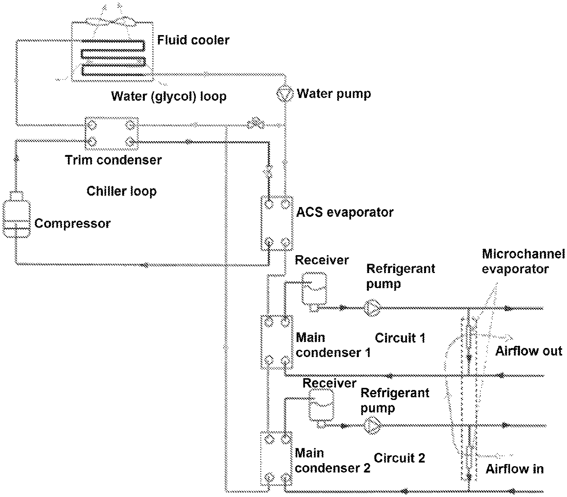
FIG. 1 is a schematic flow diagram of a cooling system in accordance with embodiments of the present disclosure.
FIG. 2 is a schematic flow diagram of an alternative embodiment of the cooling system of FIG. 1.
DETAILED DESCRIPTION
The present disclosure features a cooling system for data centers or for any other applications that have high heat rejection temperature and high sensible heat ratio compared to general air conditioning or refrigeration applications.
Some systems for data center cooling use two separate liquid refrigerant pump systems. Each pump system has its own water-cooled condenser, along with a chiller loop. The chiller loop includes a fluid cooler, a compressor, a trim condenser, and an air conditioning system (ACS) evaporator. When the outdoor ambient temperature is high, the chiller loop cools water from the outdoor fluid cooler. Further, if one of the two chiller loops fails to operate, the other is used as a backup. If both chiller loops are operable, the two of them can run in parallel for normal operation to obtain higher cooling capacity and energy efficiency.
The cooling systems and methods according to the present disclosure connect the water flow of the two chiller loop systems in a series, counter-flow arrangement. This design, together with optimal flow rate selection and control, significantly improves the system energy efficiency and reduces water flow rate and pipe size.
Some cooling systems use two circuits, each of which has a refrigerant pump loop and a water (or glycol) loop to condense the refrigerant. The water can be chilled (or "trimmed") by a compressor/chiller loop when the outdoor wet bulb temperature is high. The two circuits have parallel water flow. In normal operation, the two circuits work simultaneously, and the evaporators for air cooling of the two circuits are in series, and air from the high temperature circuit enters the evaporator of the low temperature circuit to be cooled further.
If one of the two circuits fails to operate, the system operates in "failure mode" or "backup mode" with only one circuit in operation. The cooling system of the present disclosure employs two circuits, but the water (or glycol) flows through the two circuits in series and counter flow pattern, resulting in higher energy efficiency, lower water flow rate, and a broader operating range, e.g., it can run with a higher outdoor wet bulb temperature.
FIG. 1 is a schematic flow diagram of a cooling system in accordance with embodiments of the present disclosure. As shown, water (or glycol) from the fluid cooler is pumped first through the ACS evaporator where it is chilled (when ambient or wetbulb temperature is high), and then through main condenser 1 and main condenser 2 of the two pumped refrigerant fluid circuits. From the main condensers, the water (or glycol/water mixture) is mixed with additional water from the outlet of the fluid cooler, and then goes through the trim condenser and finally through the fluid cooler, completing the cycle. Alternatively, the water from the main condenser 2 is mixed with the water leaving the trim condenser at the outlet of the trim condenser and returns to the fluid cooler.
The two main pumped refrigerant fluid circuits are connected to evaporators at or near the heat source (e.g., mounted on the rear doors or tops of computer server cabinets or from the ceiling above the cabinets to cool the electronic equipment). Air and water flow of the two fluid circuits is in a counter flow arrangement: warm air (e.g., 40.degree. C.) from electronic equipment is cooled in the first evaporator to a lower temperature (e.g., 32.degree. C.), and then air leaving fluid circuit 2 enters the evaporator of fluid circuit 1 and is further cooled (e.g., to 25.degree. C.). In other words, chilled water from the ACS evaporator is in thermal communication with the first and second fluid circuits, and the chilled water and the refrigerant flowing through the first and second fluid circuits are in thermal counter flow: the chilled water is first in thermal communication with the refrigerant with lower temperature (corresponding to lower air temperature in the evaporator) in fluid circuit 1 through the main condenser 1, with its temperature raised, and then is in thermal communication with the refrigerant with higher temperature (corresponding to higher air temperature in the evaporator) in fluid circuit 2 through the main condenser 2, with its temperature further raised. In embodiments, the evaporators may include microchannel evaporators.
The refrigerant saturation temperature of fluid circuit 1 is maintained lower than fluid circuit 2 (e.g., 24.degree. C. for fluid circuit 1 versus 31.degree. C. for fluid circuit 2); the water (or glycol) from the fluid cooler or ACS evaporator with lower temperature flows through main condenser 1 to condense refrigerant vapor in fluid circuit 1, with its temperature raised, and then flows through main condenser 2 to condense refrigerant vapor in fluid circuit 2, with its temperature further raised, then flows to the trim condenser. This flow arrangement plus optimal water (or glycol) flow rate control can increase system energy efficiency and significantly reduce water flow rate, pipe size and pumping power.
The two refrigerant fluid circuits 1 and 2 shown in FIG. 1 can also be used with a chiller plant. Chilled water from the chiller plant flows through the main condenser 1 of the fluid circuit 1, and then through the main condenser 2 of the fluid circuit 2, and then returns to the chiller plant with a higher temperature. In other words, the chiller plant may replace the water and chiller loops of FIG. 1. Thus, the output of the chiller plant is provided to the input of the water side of main condenser 1 and the output of the water side of main condenser 2 is provided to the input of the chiller plant. The chiller plant may provide chilled water to multiple refrigerant distribution units including fluid circuits 1 and 2. Compared to conventional CRAC units, this design has a lower water flow rate, and consumes much less pumping and compressor power.
Although the illustrative embodiments of the present disclosure have been described herein with reference to the accompanying drawings, it is to be understood that the disclosure is not limited to those precise embodiments, and that various other changes and modification may be effected therein by one skilled in the art without departing from the scope or spirit of the disclosure.
In embodiments, the water flow through the trim condenser and the water flow through the ACS evaporator, the first main condenser, and the second main condenser, may be in a series or in a parallel arrangement. FIG. 1 shows the in series arrangement. The in parallel arrangement is illustrated in FIG. 2 and may be formed by disconnecting the output of the water side of main condenser 2 from the fluid line or fluid conduit connected between the water pump and the input to the water loop side of the trim condenser, and connecting the output of the water side of main condenser 2 to the fluid line or fluid conduit connected between the output of the water loop side of the trim condenser and the input to the fluid cooler.
Other applications for the cooling system of the present disclosure include turbine inlet air cooling, laboratory system cooling, and electronics cooling, among many others.
* * * * *
References
-
h20565.www2.hp.com/hpsc/doc/public/display?docId=emr_na-c00613691
-
intel.in/content/dam/www/public/us/en/documents/white-papers/date-center-efficiency-air-cooled-bkms-paper.pdf
-
shared.liebert.com/SharedDocuments/LiebertFiles/SL_16655_REV09_07-09.pdf
-
cse.iitb.ac.in/.about.puru/courses/autumn12/cs695/downloads/dcevolve.pdf
-
-
smartech.gatech.edu/bitstream/handle/1853/14605/rambo_jeffrey_200605_phd.pdf
D00000
D00001
D00002
XML
uspto.report is an independent third-party trademark research tool that is not affiliated, endorsed, or sponsored by the United States Patent and Trademark Office (USPTO) or any other governmental organization. The information provided by uspto.report is based on publicly available data at the time of writing and is intended for informational purposes only.
While we strive to provide accurate and up-to-date information, we do not guarantee the accuracy, completeness, reliability, or suitability of the information displayed on this site. The use of this site is at your own risk. Any reliance you place on such information is therefore strictly at your own risk.
All official trademark data, including owner information, should be verified by visiting the official USPTO website at www.uspto.gov. This site is not intended to replace professional legal advice and should not be used as a substitute for consulting with a legal professional who is knowledgeable about trademark law.