Vehicle having controllable target driving force
Hirasawa , et al. April 19, 2
U.S. patent number 11,305,770 [Application Number 16/837,180] was granted by the patent office on 2022-04-19 for vehicle having controllable target driving force. This patent grant is currently assigned to TOYOTA JIDOSHA KABUSHIKI KAISHA. The grantee listed for this patent is TOYOTA JIDOSHA KABUSHIKI KAISHA. Invention is credited to Takahiko Hirasawa, Keiji Kaita.


| United States Patent | 11,305,770 |
| Hirasawa , et al. | April 19, 2022 |
Vehicle having controllable target driving force
Abstract
A vehicle includes a drive device for traveling, and a control device configured to control the drive device so that the vehicle travels with a target driving force based on an accelerator operation amount. The control device is configured to set the target driving force such that a change in the target driving force with respect to a change in the accelerator operation amount is gentler in a case where steady traveling is desired as compared with a case where the steady traveling is not desired. Therefore, in a case where the steady traveling is desired, a variation of a vehicle speed with respect to a slight variation of the accelerator operation amount can be gentle and continuous steady traveling can be facilitated.
| Inventors: | Hirasawa; Takahiko (Toyota, JP), Kaita; Keiji (Miyoshi, JP) | ||||||||||
|---|---|---|---|---|---|---|---|---|---|---|---|
| Applicant: |
|
||||||||||
| Assignee: | TOYOTA JIDOSHA KABUSHIKI KAISHA
(Toyota, JP) |
||||||||||
| Family ID: | 1000006246143 | ||||||||||
| Appl. No.: | 16/837,180 | ||||||||||
| Filed: | April 1, 2020 |
Prior Publication Data
| Document Identifier | Publication Date | |
|---|---|---|
| US 20210001855 A1 | Jan 7, 2021 | |
Foreign Application Priority Data
| Jul 3, 2019 [JP] | JP2019-124180 | |||
| Current U.S. Class: | 1/1 |
| Current CPC Class: | B60W 30/18072 (20130101); B60W 10/04 (20130101); B60W 30/20 (20130101); B60W 2520/10 (20130101); B60W 2510/0604 (20130101) |
| Current International Class: | B60W 30/00 (20060101); B60W 30/18 (20120101); B60W 10/04 (20060101); B60W 30/20 (20060101) |
References Cited [Referenced By]
U.S. Patent Documents
| 2014/0018974 | January 2014 | Okita |
| 2018/0178796 | June 2018 | Fukuda |
| 2019/0217860 | July 2019 | Kishi |
| 2020/0164870 | May 2020 | Takahashi |
| 2021/0276550 | September 2021 | Gotou |
| 2013-010426 | Jan 2013 | JP | |||
Assistant Examiner: Peko; Brittany Renee
Attorney, Agent or Firm: Oliff PLC
Claims
What is claimed is:
1. A vehicle comprising: a drive device for traveling; and a control device configured to control the drive device so that the vehicle travels with a target driving force based on an accelerator operation amount, wherein the control device is configured to set the target driving force such that a change in the target driving force with respect to a change in the accelerator operation amount is gentler in a case where steady traveling is desired as compared with a case where the steady traveling is not desired, and wherein the control device is configured to set a request driving force for traveling based on the accelerator operation amount and a vehicle speed or a driving force obtained by performing smoothing on the request driving force as the target driving force, and determine that the steady traveling is desired in a case where a difference between the request driving force and travel resistance is equal to or smaller than a predetermined difference.
2. The vehicle according to claim 1, wherein the control device is configured to determine that the steady traveling is desired in a case where the difference between the request driving force and the travel resistance is equal to or smaller than the predetermined difference and a variation amount of the accelerator operation amount for a predetermined time is equal to or smaller than a predetermined variation amount.
Description
INCORPORATION BY REFERENCE
The disclosure of Japanese Patent Application No. 2019-124180 filed on Jul. 3, 2019 including the specification, drawings and abstract is incorporated herein by reference in its entirety.
BACKGROUND
1. Technical Field
The present disclosure relates to a vehicle.
2. Description of Related Art
In the related art, as such a kind of vehicles, a vehicle has been proposed in which acceleration and deceleration of the vehicle is controlled based on an operation position of an accelerator pedal (Japanese Unexamined Patent Application Publication No. 2013-10426 (JP 2013-10426 A)).
SUMMARY
In the vehicle, the acceleration and deceleration changes in a uniform change manner (a change rate) with respect to a change in the operation position of the accelerator pedal, regardless of whether a steady traveling (traveling at a substantially constant vehicle speed) is desired. Therefore, even in a case where the steady traveling is desired, as the operation position of the accelerator pedal changes, the vehicle speed changes quickly to a certain extent, the steady traveling is unlikely to be continued.
The main object of a vehicle of an aspect of the present disclosure is to facilitate continuous steady traveling in a case where the steady traveling is desired.
The vehicle of an aspect of the present disclosure employs the following means to achieve the main object described above.
A first aspect of the present disclosure relates to a vehicle including a drive device for traveling and a control device. The control device is configured to control the drive device so that the vehicle travels with a target driving force based on an accelerator operation amount. The control device is configured to set the target driving force such that a change in the target driving force with respect to a change in the accelerator operation amount is gentler in a case where steady traveling is desired as compared with a case where the steady traveling is not desired.
In the vehicle according to the first aspect, when the drive device is controlled so that the vehicle travels with the target driving force based on the accelerator operation amount, the target driving force is set such that a change in the target driving force with respect to a change in the accelerator operation amount is gentler in a case where steady traveling is desired as compared with a case where the steady traveling is not desired. Accordingly, in a case where the steady traveling is desired, a variation of a vehicle speed with respect to a slight variation of the accelerator operation amount can be gentle and continuous steady traveling can be facilitated.
In the vehicle according to the first aspect, the control device may be configured to determine that the steady traveling is desired in a case where a variation amount of the accelerator operation amount for a predetermined time is equal to or smaller than a first predetermined variation amount and a variation amount of a vehicle speed for the predetermined time is equal to or smaller than a second predetermined variation amount.
In this way, the determination can be made as to whether the steady traveling is desired by using the variation amount of the accelerator operation amount and the variation amount of the vehicle speed.
In the vehicle according to the first aspect, the control device may be configured to set a request driving force for traveling based on the accelerator operation amount and a vehicle speed or a driving force obtained by performing smoothing on the request driving force as the target driving force, and determine that the steady traveling is desired in a case where a difference between the request driving force and travel resistance is equal to or smaller than a predetermined difference. In this way, the determination can be made as to whether the steady traveling is desired by using the difference between the request driving force and the travel resistance.
In the vehicle according to the first aspect, the control device may be configured to determine that the steady traveling is desired in a case where the difference between the request driving force and the travel resistance is equal to or smaller than the predetermined difference and a variation amount of the accelerator operation amount for a predetermined time is equal to or smaller than a predetermined variation amount. In this way, the determination can be more appropriately made as to whether the steady traveling is desired.
BRIEF DESCRIPTION OF THE DRAWINGS
Features, advantages, and technical and industrial significance of exemplary embodiments of the present disclosure will be described below with reference to the accompanying drawings, in which like signs denote like elements, and wherein:
FIG. 1 is a configuration diagram showing an outline of a configuration of an electric vehicle 20 as a first embodiment of the present disclosure;
FIG. 2 is an explanatory diagram showing an example of a map for request driving force setting;
FIG. 3 is a flowchart showing an example of a target driving force setting process executed by an electronic control unit 50;
FIG. 4 is a flowchart showing an example of a target driving force setting process according to a modification example;
FIG. 5 is an explanatory diagram showing an example of a map for travel resistance estimation;
FIG. 6 is a configuration diagram showing an outline of a configuration of a hybrid vehicle 120 according to a modification example;
FIG. 7 is a configuration diagram showing an outline of a configuration of a hybrid vehicle 220 according to a modification example; and
FIG. 8 is a configuration diagram showing an outline of a configuration of a hybrid vehicle 320 according to a modification example.
DETAILED DESCRIPTION OF EMBODIMENTS
Hereinafter, an embodiment for carrying out the present disclosure will be described.
FIG. 1 is a configuration diagram showing an outline of a configuration of an electric vehicle 20 as a first embodiment of the present disclosure. As shown, the electric vehicle 20 according to the first embodiment includes a motor 32, an inverter 34, a battery 36 as a power storage device, a navigation device 40, and an electronic control unit 50.
The motor 32 is configured as, for example, a synchronous generator motor, and has a rotor connected to a drive shaft 26 that is coupled to the drive wheels 22a, 22b via a differential gear 24. The inverter 34 is used to drive the motor 32 and connected to the battery 36 via a power line. The motor 32 is rotationally driven by switching controlling a plurality of switching elements of the inverter 34 by the electronic control unit 50. The battery 36 is configured as, for example, a lithium ion secondary battery or a nickel hydride secondary battery.
The navigation device 40 includes a main body, a GPS antenna, and a display. The main body includes a CPU, a ROM, a RAM, a storage medium, an input/output port, and a communication port, that are not shown. The storage medium of the main body stores map information and the like. As the map information, service information (for example, sightseeing information or parking lots), road information of each traveling section (for example, between traffic lights or intersections), or the like is stored as a database. The road information includes distance information, width information, lane number information, region information (a city area or a suburb), road kind information (a general road or an expressway), gradient information, a legal speed, or the number of traffic lights. The GPS antenna receives information on the current location of the vehicle. The display is configured as a touch panel display that displays various kinds of information such as information on the current location of the vehicle or a travel scheduled route to the destination and allows a user to input various instructions. The navigation device 40 is connected to the electronic control unit 50 via the communication port.
The electronic control unit 50 is configured as a microprocessor centered on a CPU (not shown). In addition to the CPU, the electronic control unit 50 includes a ROM that stores a processing program, a RAM that temporarily stores data, an input/output port, and a communication port. Signals from various sensors are input to the electronic control unit 50 via the input port. Examples of the signals input to the electronic control unit 50 include a rotational position .theta.m of the rotor of the motor 32 from a rotational position sensor that detects the rotational position of the rotor of the motor 32, or phase currents Iu, Iv of the motor 32 from a current sensor that detects each phase current of the motor 32. Examples of the signals input to the electronic control unit 50 also include a voltage Vb of the battery 36 from a voltage sensor attached between terminals of the battery 36, a current Ib of the battery 36 from the current sensor attached to an output terminal of the battery 36, or a temperature Tb of the battery 36 from a temperature sensor attached to the battery 36. Examples of the signals input to the electronic control unit 50 also include an ignition signal from an ignition switch 60, or a shift position SP from a shift position sensor 62 that detects an operation position of a shift lever 61. Examples of the signals input to the electronic control unit 50 also include an accelerator operation amount Acc from an accelerator pedal position sensor 64 that detects a stepping amount of an accelerator pedal 63, a brake pedal position BP from a brake pedal position sensor 66 that detects a stepping amount of a brake pedal 65, a vehicle speed V from a vehicle speed sensor 68, or a road surface gradient Or (the uphill side is defined as positive) from a gradient sensor 69.
The electronic control unit 50 outputs various control signals via the output port. Examples of the signals output from the electronic control unit 50 include a switching control signal to the plurality of switching elements of the inverter 34. The electronic control unit 50 calculates an electrical angle .theta.e or a rotation speed Nm of the motor 32 based on the rotational position .theta.m of the rotor of the motor 32 from the rotational position sensor. The electronic control unit 50 is connected to the navigation device 40 via the communication port.
In the electric vehicle 20 according to the first embodiment configured as described above, the electronic control unit 50 firstly sets a request driving force Tdtag for traveling based on the accelerator operation amount Acc from the accelerator pedal position sensor 64 and the vehicle speed V from the vehicle speed sensor 68. The request driving force Tdtag is set by a method, for example, in which a relationship between the accelerator operation amount Acc and the vehicle speed V and the request driving force Tdtag is predetermined and stored in the ROM (not shown) as a map for request driving force setting, and when the accelerator operation amount Acc and the vehicle speed V are applied, the corresponding request driving force Tdtag is derived from the map. FIG. 2 is an explanatory diagram showing an example of a map for request driving force setting. Subsequently, the electronic control unit 50 sets a target driving force Td* for traveling based on the request driving force Tdtag, and sets a torque command Tm* of the motor 32 so that the vehicle travels with the set target driving force Td*. The electronic control unit 50 performs switching control of the plurality of switching elements of the inverter 34 so that the motor 32 is driven by the torque command Tm*.
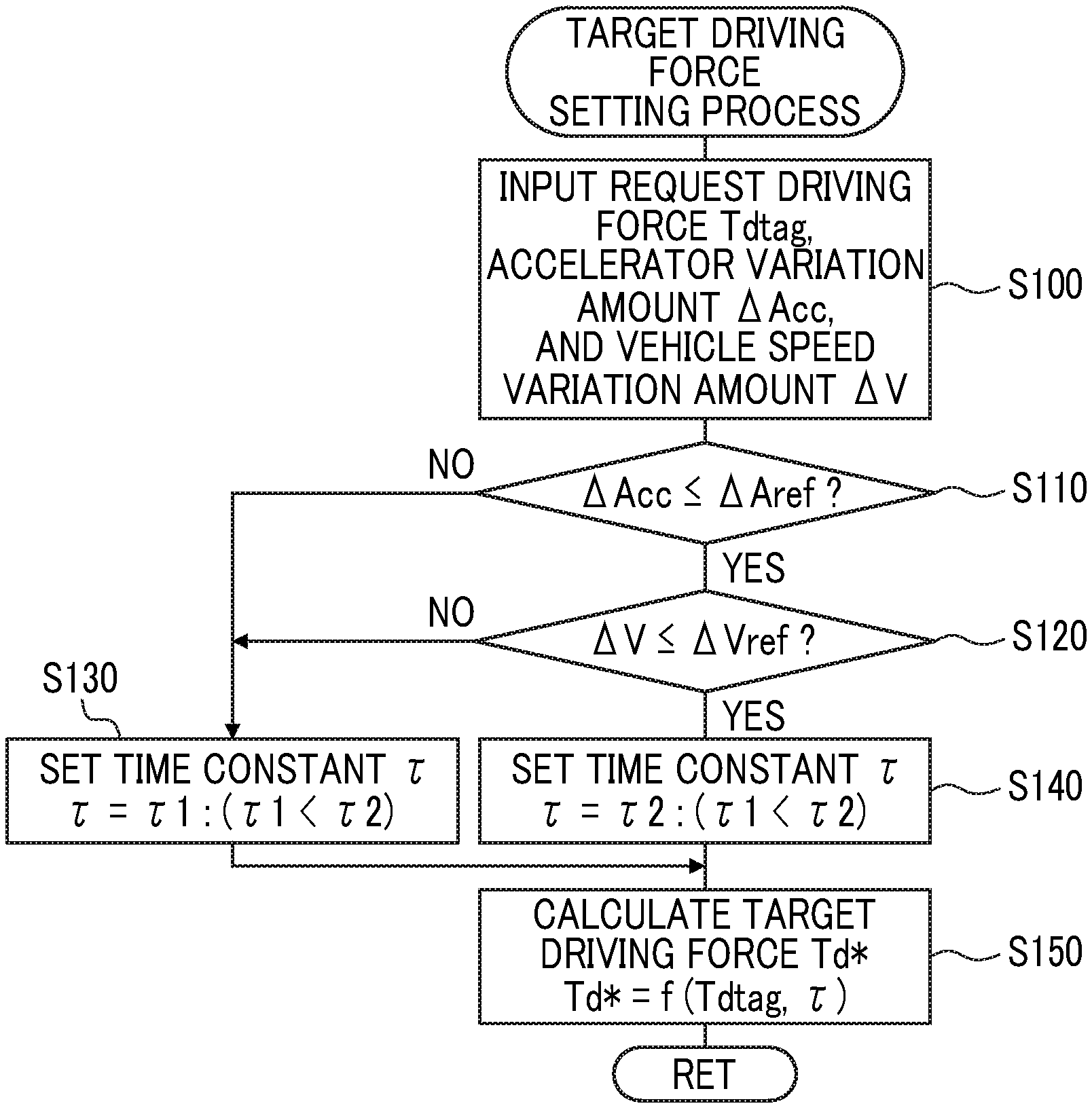
Next, the operation of the electric vehicle 20 according to the first embodiment configured as described above, in particular, the operation when the target driving force Td* is set based on the request driving force Tdtag will be described. FIG. 3 is a flowchart showing an example of a target driving force setting process executed by the electronic control unit 50. The routine is repeatedly executed.
When the target driving force setting process of FIG. 3 is executed, the electronic control unit 50 firstly inputs data such as the request driving force Tdtag or an accelerator variation amount .DELTA.Acc and a vehicle speed variation amount .DELTA.V that are variation amounts of the accelerator operation amount Acc and the vehicle speed V for a predetermined time T1 (for example, about several hundred msec to several sec) (step S100). A value set based on the accelerator operation amount Acc and the vehicle speed V is input as the request driving force Tdtag. A value calculated as a difference between a maximum value and a minimum value of each of the accelerator operation amount Acc and the vehicle speed V for the predetermined time T1 is input as the accelerator variation amount .DELTA.Acc and the vehicle speed variation amount .DELTA.V.
After the data is input, the input accelerator variation amount .DELTA.Acc is compared with a threshold value .DELTA.Aref (step S110) and the vehicle speed variation amount .DELTA.V is compared with a threshold value .DELTA.Vref (step S120). The threshold value .DELTA.Aref is a threshold value used to determine whether a variation of the accelerator operation amount Acc is relatively small, and for example, a value of about 1% to 5% is used. The threshold value .DELTA.Vref is used to determine whether a variation of the vehicle speed V is relatively small, and for example, a value of about 1 km/h to 5 km/h is used. A case where the variation of the accelerator operation amount Acc and the variation of the vehicle speed V are relatively small is assumed that the driver desires steady traveling. Accordingly, processing of steps S110, S120 can be considered as processing for determining whether the steady traveling is desired.
A case where the accelerator variation amount .DELTA.Acc is greater than the threshold value .DELTA.Aref in step S110 or a case where the vehicle speed variation amount .DELTA.V is greater than the threshold value .DELTA.Vref in step S120 are determined that the steady traveling is not desired, a predetermined value .tau.1 that is relatively small is set as a time constant .tau. used in smoothing (step S130), the request driving force Tdtag is smoothed using the set time constant .tau. to calculate the target driving force Td* (step S150), and the routine ends. The target driving force Td* can be calculated by Expression (1) using a previous target driving force (previous Td*), the request driving force Tdtag, and the time constant .tau., for example. Td*=previous Td*.tau.+Tdtag(1-.tau.) (1)
A case where the accelerator variation amount .DELTA.Acc is equal to or smaller than the threshold value .DELTA.Aref in step S110 or a case where the vehicle speed variation amount .DELTA.V is equal to or smaller than the threshold value .DELTA.Vref in step S120 are determined that the steady traveling is desired, a predetermined value .tau.2 greater than the predetermined value .tau.1 is set as a time constant .tau. used in smoothing (step S140), the request driving force Tdtag is smoothed using the set time constant .tau. to calculate the target driving force Td* (step S150), and the routine ends. Accordingly, the target driving force Td* is changed gently with respect to a change in the accelerator operation amount Acc (a change of the request driving force Tdtag) in a case where steady traveling is desired as compared with a case where the steady traveling is not desired, and thus a variation of the vehicle speed V can be gentle and continuous steady traveling can be facilitated.
In the electric vehicle 20 according to the first embodiment described above, the request driving force Tdtag is smoothed using the greater time constant .tau. to calculate the target driving force Td* and the motor 32 is controlled so that the vehicle travels with the target driving force Td* in a case where the steady traveling is desired (a case where the accelerator variation amount .DELTA.Acc is equal to or smaller than the threshold value .DELTA.Aref and the vehicle speed variation amount .DELTA.V is equal to or smaller than the threshold value .DELTA.Vref), as compared with a case where the steady traveling is not desired (a case where the accelerator variation amount .DELTA.Acc is greater than the threshold value .DELTA.Aref and the vehicle speed variation amount .DELTA.V is greater than the threshold value .DELTA.Vref). Accordingly, a variation of the vehicle speed V can be gentler with respect to a slight variation in the accelerator operation amount Acc in a case where the steady traveling is desired, and thus continuous steady traveling can be facilitated.
Hereinafter, an electric vehicle 20B according to a second embodiment will be described. The electric vehicle 20B according to the second embodiment has the same hardware configuration as the electric vehicle 20 according to the first embodiment shown in FIG. 1. Therefore, in order to avoid redundant description, the hardware configuration of the electric vehicle 20B according to the second embodiment is denoted by the same reference numerals as the electric vehicle 20 according to the first embodiment firstly described, and detailed description will be omitted.
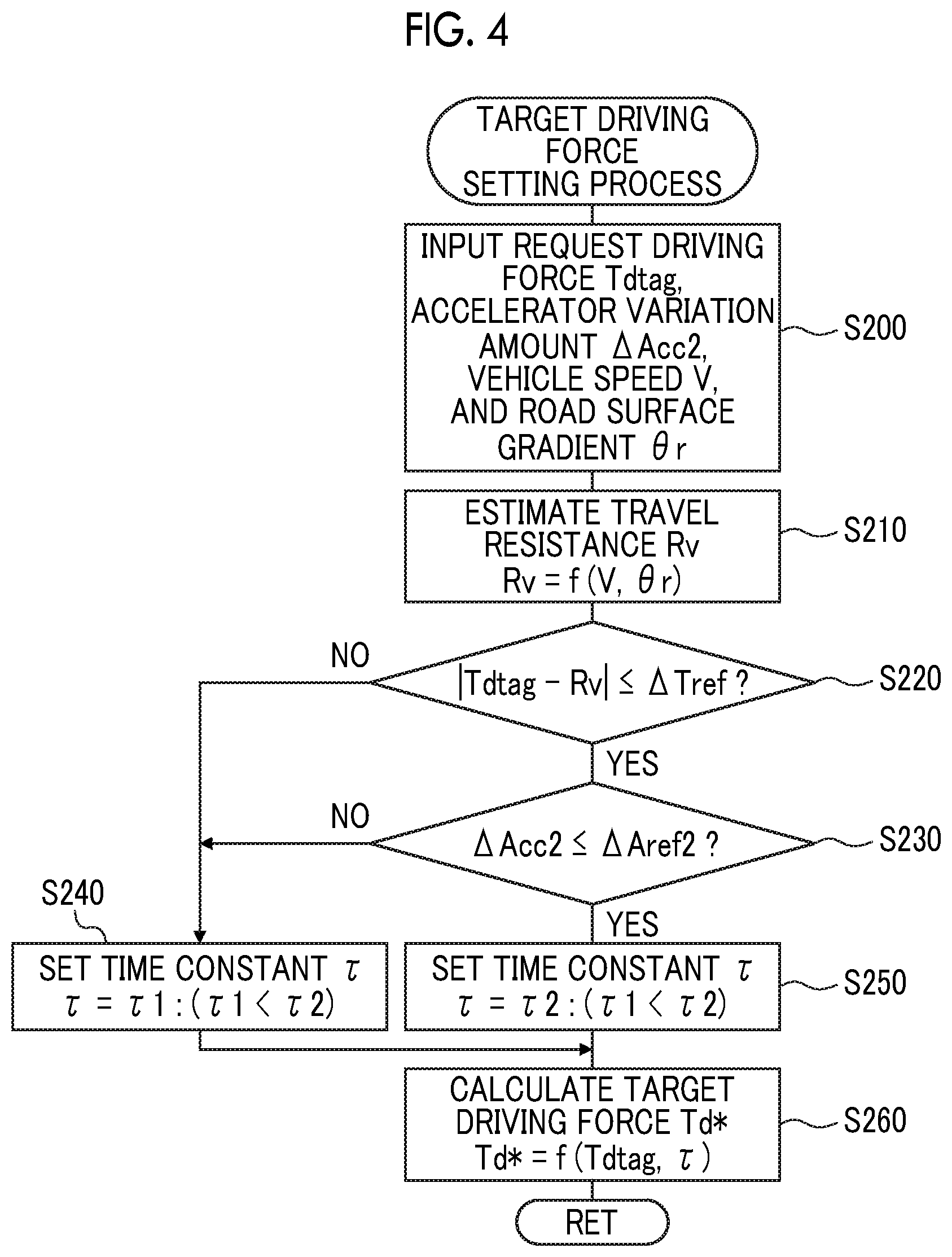
Subsequently, the operation of the electric vehicle 20B according to the second embodiment will be described. The electronic control unit 50 according to the second embodiment executes a target driving force setting process of FIG. 4 instead of the target driving force setting process of FIG. 3.
When the target driving force setting process of FIG. 4 is executed, the electronic control unit 50 firstly inputs data such as the request driving force Tdtag or a second accelerator variation amount .DELTA.Acc2 that is a variation amount of the accelerator operation amount Acc for a predetermined time T2 (for example, about several hundred .mu.sec to several msec), a vehicle speed V, and a road surface gradient Or (the uphill side is defined as positive) (step S200). The request driving force Tdtag is input in the same manner as in the target driving force setting process of FIG. 3. A value calculated as a difference between a maximum value and a minimum value of the accelerator operation amount Acc for the predetermined time T2 is input as the second accelerator variation amount .DELTA.Acc2. A value detected by the vehicle speed sensor 68 is input as the vehicle speed V. A value detected by the gradient sensor 69 is input as the road surface gradient .theta.r.
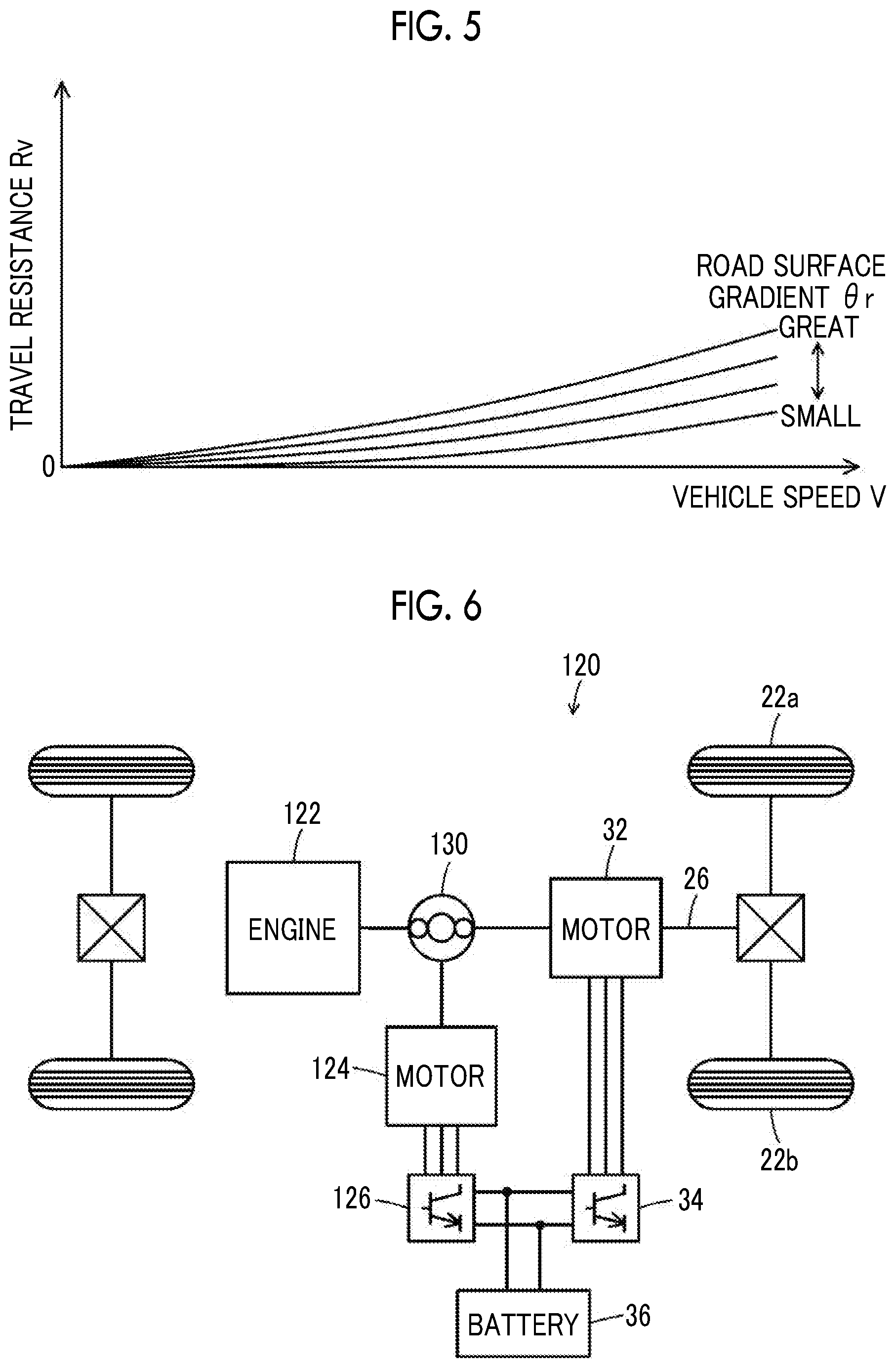
After the data is input, travel resistance Rv is estimated based on the input vehicle speed V and road surface gradient .theta.r (step S210). The travel resistance Rv is a force acting on the vehicle in a direction opposite to the traveling direction, and the travel resistance Rv includes rolling resistance, air resistance, gradient resistance, acceleration resistance, or the like. In the second embodiment, the travel resistance Rv is estimated by a method, for example, in which a relationship between the vehicle speed V and the road surface gradient .theta.r and the travel resistance Rv is predetermined and stored in the ROM (not shown) as a map for travel resistance estimation, and when the vehicle speed V and the road surface gradient .theta.r are applied, the corresponding travel resistance Rv is derived from the map. FIG. 5 is an explanatory diagram showing an example of a map for travel resistance estimation. As shown, the travel resistance Rv is estimated to increase as the vehicle speed V increases, and to increase as the road surface gradient .theta.r increases toward the uphill road side.
Subsequently, a difference between the request driving force Tdtag and the travel resistance Rv is compared with the threshold value .DELTA.Tref (step S220) and the second accelerator variation amount .DELTA.Acc2 is compared with the threshold value .DELTA.Aref2 (step S230). The threshold value .DELTA.Tref is a threshold value used to determine whether the request driving force Tdtag (a force in the traveling direction) and the travel resistance Rv (a force in the opposite direction of the traveling direction) are balanced to a certain extent, and for example, a value of about 1 Nm to 5 Nm is used. The threshold value .DELTA.Aref2 is a threshold value used to determine whether the driver has performed a sudden accelerator operation (stepping on or stepping back), and for example, a value of about 1 km/h to 5 km/h is used. A case where the request driving force Tdtag and the travel resistance Rv are balanced to a certain extent and the driver does not perform a sudden accelerator operation is assumed that the driver desires the steady traveling. Accordingly, processing of steps S220, S230 can be considered as processing for determining whether the steady traveling is desired.
A case where the difference between the request driving force Tdtag and the travel resistance Rv is greater than the threshold value .DELTA.Tref in step S220 or a case where the second accelerator variation amount .DELTA.Acc2 is greater than the threshold value .DELTA.Aref2 in step S230 are determined that the steady traveling is not desired, a predetermined value .tau.1 that is relatively small is set as a time constant .tau. used in smoothing (step S240), the request driving force Tdtag is smoothed using the set time constant .tau. to calculate the target driving force Td* (step S260), and the routine ends. The target driving force Td* can be calculated by Expression (1) using the previous target driving force (previous Td*) and the request driving force Tdtag and the time constant .tau., for example.
A case where the difference between the request driving force Tdtag and the travel resistance Rv is equal to or smaller than the threshold value .DELTA.Tref in step S220 or a case where the second accelerator variation amount .DELTA.Acc2 is equal to or smaller than the threshold value .DELTA.Aref2 in step S230 are determined that the steady traveling is desired, a predetermined value .tau.2 greater than the predetermined value .tau.1 is set as a time constant .tau. used in smoothing (step S250), the request driving force Tdtag is smoothed using the set time constant .tau. to calculate the target driving force Td* (step S260), and the routine ends. Accordingly, the target driving force Td* is changed gently with respect to a change in the accelerator operation amount Acc (a change of the request driving force Tdtag) in a case where steady traveling is desired as compared with a case where the steady traveling is not desired, and thus a variation of the vehicle speed V can be gentle and continuous steady traveling can be facilitated.
In the electric vehicle 20B according to the second embodiment described above, the request driving force Tdtag is smoothed using the greater time constant .tau. to calculate the target driving force Td* and the motor 32 is controlled so that the vehicle travels with the target driving force Td* in a case where the steady traveling is desired (a case where the difference between the request driving force Tdtag and the travel resistance Rv is equal to or smaller than the threshold value .DELTA.Tref and the second accelerator variation amount .DELTA.Acc2 is equal to or smaller than the threshold value .DELTA.Aref2), as compared with a case where the steady traveling is not desired (a case where the difference between the request driving force Tdtag and the travel resistance Rv is greater than the threshold value .DELTA.Tref and the second accelerator variation amount .DELTA.Acc2 is greater than the threshold value .DELTA.Aref2). Accordingly, a variation of the vehicle speed V can be gentler with respect to a slight variation in the accelerator operation amount Acc in a case where the steady traveling is desired, and thus continuous steady traveling can be facilitated.
In the electric vehicle 20B according to the second embodiment, the determination is made as to whether the steady traveling is desired based on the difference between the request driving force Tdtag and the travel resistance Rv, and the second accelerator variation amount .DELTA.Acc2. However, the determination may be made as to whether the steady traveling is desired based on only the difference between the request driving force Tdtag and the travel resistance Rv without considering the second accelerator variation amount .DELTA.Acc2.
In the electric vehicle 20B according to the second embodiment, the travel resistance Rv is estimated based on the vehicle speed V and the road surface gradient .theta.r from the gradient sensor 69. However, instead of the road surface gradient .theta.r from the gradient sensor 69, a road surface gradient .theta.r2 extracted based on the current location of the vehicle and the map information (the gradient information) by the navigation device 40 may be used.
In the electric vehicle 20B according to the second embodiment, the travel resistance Rv is estimated based on the vehicle speed V and the road surface gradient .theta.r. However, the travel resistance Rv may be estimated based on only the vehicle speed V without considering the road surface gradient .theta.r.
In the electric vehicles 20, 20B according to the first and second embodiments, the request driving force Tdtag is smoothed using the greater time constant .tau. to calculate the target driving force Td* in a case where the steady traveling is desired as compared with a case where the steady traveling is not desired. However, the request driving force Tdtag is subjected to rate processing using the smaller rate value Rt to calculate the target driving force Td* in a case where the steady traveling is desired as compared with a case where the steady traveling is not desired. In this case, the target driving force Td* can be calculated by Expression (2) using the previous target driving force (previous Td*) and the request driving force Tdtag and the rate value Rt, for example. Td*=max(min(Tdtag,previous Td*+Rt), previous Td*-Rt) (2)
In the electric vehicles 20, 20B according to the first and second embodiments, in a case where the steady traveling is not desired, the request driving force Tdtag is smoothed using the relatively small time constant .tau. to calculate the target driving force Td*. In the modification example, in a case where the steady traveling is not desired, the target driving force Td* is calculated by using the relatively great rate value Rt and performing rate processing on the request driving force Tdtag. However, in a case where the steady traveling is not desired, the request driving force Tdtag may be set as the target driving force Td*.
In the electric vehicles 20, 20B according to the first and second embodiments, the battery 36 is used as the power storage device, but a capacitor may be used.
In the first and second embodiments, a configuration of the electric vehicles 20, 20B including the traveling motor 32 and the battery 36 are adopted. However, a configuration of a hybrid vehicle including an engine in addition to the traveling motor 32 and the battery 36 may be adopted, a configuration of a fuel cell vehicle including a fuel cell in addition to the traveling motor 32 and the battery 36 may be adopted, and a configuration of a general engine vehicle including the engine without the motor 32 and the battery 36 may be adopted.
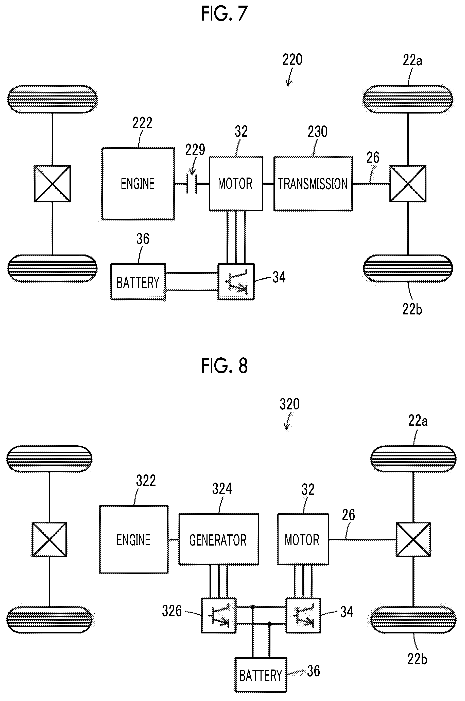
Example of the hybrid vehicle includes a configuration in which the motor 32 is connected to the drive shaft 26 coupled to the drive wheels 22a, 22b, an engine 122 and the motor 124 are connected to the drive shaft 26 via a planetary gear 130, and the battery 36 is connected to the motors 32, 124 via the inverters 34, 126, as shown in a hybrid vehicle 120 of a modification example in FIG. 6. Example of the hybrid vehicle also includes a configuration in which the motor 32 is connected to the drive shaft 26 coupled to the drive wheels 22a, 22b via transmission 230, an engine 222 is connected to the motor 32 via a clutch 229, and the battery 36 is connected to the motor 32 via the inverter 34, as shown in a hybrid vehicle 220 of a modification example in FIG. 7. Example of the hybrid vehicle also includes a configuration in which the motor 32 is connected to the drive shaft 26 coupled to the drive wheels 22a, 22b, a generator 324 is connected to an engine 322, and the battery 36 is connected to the motor 32 and the generator 324 via the inverters 34, 326, as shown in a hybrid vehicle 320 of a modification example in FIG. 8.
The correspondence between the main elements of the embodiment and the main elements of the present disclosure described in the Summary section will be described. In the first and second embodiments, the motor 32 corresponds to the "drive device", and the electronic control unit 50 corresponds to the "control device".
The correspondence between the main elements of the embodiment and the main elements of the present disclosure described in the Summary section is not construed to limit elements of the present disclosure described in the Summary section, since the embodiment is an example to specifically describe the mode for carrying out the present disclosure described in the Summary section. That is, the interpretation of the present disclosure described in the Summary section should be made based on the description of the section, and the embodiment is only the specific example of the present disclosure described in the Summary section.
As described above, the aspect of implementing the present disclosure has been described using the embodiment. However, an applicable embodiment of the present disclosure is not limited to the embodiments above, and various modifications could be made without departing from the scope of the present disclosure.
The present disclosure can be used in the manufacturing industry of vehicles.
* * * * *
D00000
D00001
D00002
D00003
D00004
D00005
D00006
XML
uspto.report is an independent third-party trademark research tool that is not affiliated, endorsed, or sponsored by the United States Patent and Trademark Office (USPTO) or any other governmental organization. The information provided by uspto.report is based on publicly available data at the time of writing and is intended for informational purposes only.
While we strive to provide accurate and up-to-date information, we do not guarantee the accuracy, completeness, reliability, or suitability of the information displayed on this site. The use of this site is at your own risk. Any reliance you place on such information is therefore strictly at your own risk.
All official trademark data, including owner information, should be verified by visiting the official USPTO website at www.uspto.gov. This site is not intended to replace professional legal advice and should not be used as a substitute for consulting with a legal professional who is knowledgeable about trademark law.