Arrangement for fastening an elongated object in a motor vehicle
Lindner , et al. April 19, 2
U.S. patent number 11,305,708 [Application Number 14/880,328] was granted by the patent office on 2022-04-19 for arrangement for fastening an elongated object in a motor vehicle. This patent grant is currently assigned to NEXANS. The grantee listed for this patent is NEXANS. Invention is credited to Gerhard Lindner, Hermann Teicher.

| United States Patent | 11,305,708 |
| Lindner , et al. | April 19, 2022 |
Arrangement for fastening an elongated object in a motor vehicle
Abstract
An arrangement for fastening at least one elongated object (1) in a motor vehicle is suggested, where by means of a fastening means (4) the elongated object (1) is attached to at least one fixed point on the fastening element (2). The fastening element (2) is releasably connectable to the receiving element (3) and fixedly mounted at the fixed point.
| Inventors: | Lindner; Gerhard (Plossberg, DE), Teicher; Hermann (Kohlberg, DE) | ||||||||||
|---|---|---|---|---|---|---|---|---|---|---|---|
| Applicant: |
|
||||||||||
| Assignee: | NEXANS (Courbevoie,
FR) |
||||||||||
| Family ID: | 1000006248455 | ||||||||||
| Appl. No.: | 14/880,328 | ||||||||||
| Filed: | October 12, 2015 |
Prior Publication Data
| Document Identifier | Publication Date | |
|---|---|---|
| US 20160121815 A1 | May 5, 2016 | |
Foreign Application Priority Data
| Oct 30, 2014 [EP] | 14306744 | |||
| Current U.S. Class: | 1/1 |
| Current CPC Class: | F16L 3/00 (20130101); B60R 16/0215 (20130101); B60R 16/00 (20130101); F16L 3/12 (20130101); H02G 3/32 (20130101) |
| Current International Class: | B60R 16/00 (20060101); B60R 16/02 (20060101); F16L 3/12 (20060101); F16L 3/00 (20060101); H02G 3/32 (20060101) |
| Field of Search: | ;248/74.3,74.2,73,49,74.1 |
References Cited [Referenced By]
U.S. Patent Documents
| 2144876 | January 1939 | Garnett |
| 3113754 | December 1963 | Jansson |
| 3357665 | December 1967 | Hand |
| 4518138 | May 1985 | Stutenkemper |
| 4766651 | August 1988 | Kobayashi |
| 5016843 | May 1991 | Ward |
| 5042114 | August 1991 | Parrish |
| 5234189 | August 1993 | Myers |
| 5390876 | February 1995 | Hatano et al. |
| 5494245 | February 1996 | Suzuki |
| 5564672 | October 1996 | Matson |
| 5597980 | January 1997 | Weber |
| 5775653 | July 1998 | Horney |
| 6042062 | March 2000 | Sugiyama |
| 6126122 | October 2000 | Ismert |
| 6253421 | July 2001 | Kraus |
| 6682026 | January 2004 | Nagayasu |
| 6903275 | June 2005 | Jetton |
| 7290739 | November 2007 | Zeuner |
| 7294789 | November 2007 | Watthanasintham |
| 7377472 | May 2008 | Brown |
| 7621487 | November 2009 | Brown |
| 7661631 | February 2010 | Ibaraki |
| 7836565 | November 2010 | Ho |
| 8013248 | September 2011 | Sakata |
| 8141826 | March 2012 | Gallardo |
| 9718591 | August 2017 | Lu |
| 10196013 | February 2019 | Pantino |
| 10920808 | February 2021 | Aoyama |
| 2002/0063189 | May 2002 | Coudrais |
| 2003/0000555 | January 2003 | Nagayasu |
| 2007/0257159 | November 2007 | Nelson et al. |
| 2008/0229550 | September 2008 | Elsner |
| 2009/0250559 | October 2009 | Benoit |
| 2010/0186197 | July 2010 | Inomata |
| 2010/0243855 | September 2010 | Sampson |
| 2010/0270439 | October 2010 | Li |
| 2011/0180320 | July 2011 | Thomas |
| 2012/0049011 | March 2012 | Liu |
| 2012/0091290 | April 2012 | Shitamichi |
| 2012/0097804 | April 2012 | Liu |
| 2013/0160246 | June 2013 | Hajduch |
| 2013/0291358 | November 2013 | Hebda |
| 2014/0217244 | August 2014 | Shiga |
| 2015/0136479 | May 2015 | Oga |
| 2016/0114743 | April 2016 | Miyamoto |
| 2017/0110864 | April 2017 | Akahane |
| 2017/0133827 | May 2017 | Sugino |
| 2017/0267191 | September 2017 | Chambosse |
| 2018/0022289 | January 2018 | Ishida |
| 2018/0072248 | March 2018 | Ohashi |
| 2018/0128299 | May 2018 | Katabira |
| 2018/0175596 | June 2018 | Sugino |
| 2018/0294629 | October 2018 | Volpone |
| 102008020894 | Dec 2009 | DE | |||
Other References
|
Search Report dated 2015. cited by applicant . European Office Action dated Sep. 19, 2017. cited by applicant. |
Primary Examiner: Ijaz; Muhammad
Assistant Examiner: Morris; Taylor L
Attorney, Agent or Firm: Sofer & Haroun, LLP
Claims
The invention claimed is:
1. An arrangement for fastening at least one elongated object in a motor vehicle in a form of a releasable locking mechanism, said releasable locking mechanism comprising: a plurality of receiving elements, each fastened, in a different mounting position, to different fixed points of said motor vehicle, each of said receiving elements having an opening; a plurality of fastening means, each configured to surround and couple with said at least one elongated object at a respective location associated with one of said different mounting positions of said receiving elements at said fixed points of said motor vehicle; each of said fastening means having a fastening element that is configured to be releasably connected to one of said receiving elements, said fastening element securing said receiving element to said fastening means and said elongated object, wherein the fastening element, is constructed of a bendable material, has an elongated opening running a length of said fastening element for receiving said receiving element therein, said fastening element also having an unlocking lever, a locking wedge on said unlocking lever, and a safety stirrup, said unlocking lever being formed as a bendable tab on one side of said fastening element between two cut away slots connected to a body of said fastening element at one side and extending up to another side of said fastening element and terminating in a free and at a location of said safety stirrup, said unlocking lever being capable of being bent aside within a confines of said safety stirrup, wherein in a mounting position said receiving element, at a fixed location on said motor vehicle, is fit with said elongated opening until said opening in said receiving element is connected with said locking wedge on said unlocking lever, such that said locking wedge of said unlocking lever engages in said opening of the receiving element and secures said receiving element to said fastening means and said elongated object, wherein in a releasing position, a free end of said unlocking lever is configured to be bent aside from the receiving element, without tools, until said free end of said unlocking lever contacts said safety stirrup, such that the locking wedge on said unlocking lever is moved out of the opening of the receiving element releasing said fastening element from said receiving element; and wherein said safety stirrup is elongated in a horizontal direction and further comprises an upper surface that is flush with an upper surface of said fastening element and a lower surface that tapers towards a side of the fastening element.
2. The arrangement according to claim 1, wherein the elongated object is an electric cable tree or a fluid transport line.
3. The arrangement according to claim 1, wherein said arrangement is a fastening arrangement within an engine compartment of a motor vehicle.
Description
This application claims the benefit of priority from European Patent Application No. 14 306 744.5, filed on Oct. 30, 2014, the entirety of which is incorporated by reference.
BACKGROUND
Field of the Invention
The invention relates to an arrangement for fastening at least one elongated object in a motor vehicle, wherein by means of a fastening means a fastening element is mounted on the motor vehicle and the elongated object is connected to at least one fixed point.
Description of Related Art
A plurality of different types of conductors is used in a motor vehicle. For example, the electrical elements or devices must be supplied with electrical energy. Among the electrical elements are, for example, light diodes in vehicle lamps and back lights, motors to raise and lower the windows, as well as movement of the rear view mirror, lighting the dashboard, sensors and control elements. Other systems, for example, the windshield wipers, must be supplied with liquids. The electrical elements are in a known way, by means of electrical conductors, often bound together in cable trees or cable sets, connected in the chassis to a central control arrangement. The cable sets can also contain signal conductors. Liquids can be transported by means of flexible or rigid lines.
The term an elongated object in a motor vehicle refers in the following to an electric cable tree or a fluid transport line.
The described conductors are placed within the motor vehicle and are fastened by means of support or fastening elements at certain fixed points to the vehicle body or components. In the engine cavity, the conductors are, for example, fastened to the motor and other components and extend above the same. In the mounting position, the conductors cover therefore different components, for example, filters. When repair and maintenance work has to be performed, for example, changing a filter, the conductor strands must be separated from their supports and must be bent from their position to such an extent that the elements to be processed or worked on become accessible. The support elements used comprise, for example, edge clips to which the lines are fastened by means of cable binders or similar fastening means. When the conductors come out of their supports, tools must be used and the edge clips can be damaged.
OBJECTS AND SUMMARY
It is the object of the invention to provide an arrangement for fastening of at least one elongated object in a motor vehicle which makes possible the releasable mounting of the elongated object at a fixed point, so that the elongated object can be fixed without tools as often as desired to the fixed point, and can be released again from the fixed point.
In accordance with the invention, this object is met in that the fastening element is releasably connectable to a receiving element which is fixedly attached to the fixed point.
The arrangement according to the invention permits the releasable fastening of the elongated object to a fixed point. The object can, in the case that the component underneath has to be repaired or must be exchanged, be simply and without tools bent aside and removed from the fixed point. The elongated object is by means of the fastening means permanently fastened to the fastening element and can be bent aside together therewith. After the work has been carried out, the elongated object can once again be brought into the mounting position and by means of the fastening element fastened on the fixed point. The fastening element or the receiving element is not damaged during separation or connection.
BRIEF DESCRIPTION OF THE DRAWINGS
Embodiments of the invention are illustrated in the drawings. In the drawings:
FIG. 1 shows in a perspective view an embodiment of the arrangement of the invention with a fastened elongated object,
FIG. 2 shows in a perspective view an embodiment of the arrangement of the invention of a receiving element,
FIG. 3A shows in a perspective view an embodiment of the arrangement of the invention of a fastening element,
FIG. 3B shows another view of the fastening element in 3A,
FIG. 4 shows in a perspective view three arrangements according to the invention in different embodiments attached with an elongated object,
FIG. 5A shows an embodiment of a receiving element of the arrangement according to the invention, and
FIG. 5B shows a further embodiment of an arrangement according to the invention of a receiving element.
DETAILED DESCRIPTION
In the drawings equal reference numbers refer to the same technical features.
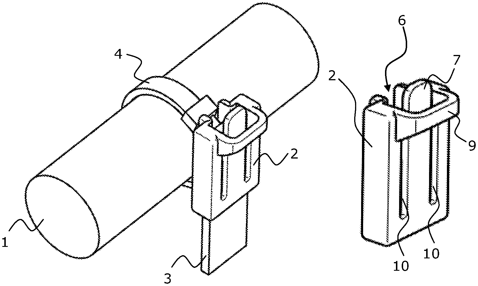
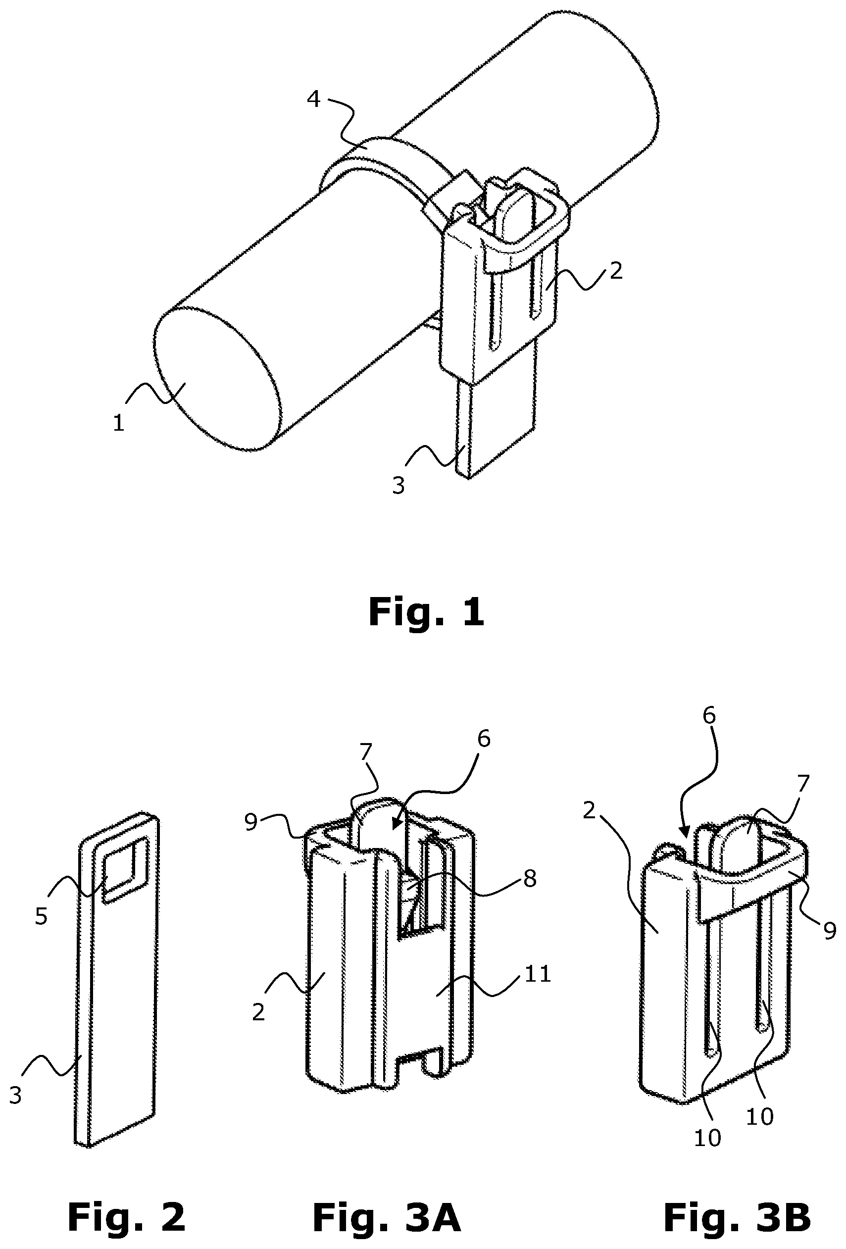
FIG. 1 shows the arrangement according to the invention with attached elongated object 1 according to a first embodiment. The elongated object is, for example, a fluid transport line or an electric cable strand. In the following the term "conductor" is to be used for short.
The arrangement comprises a fastening element 2, on which the conductor 1 is fastened by means of a fastening means 4 and a receiving element 3. The fastening means 4 is, for example, a cable clip. The fastening element 2 with the attached conductor is fastened to the receiving element 3. The two elements 2, 3 engage each other through a locking mechanism.
FIG. 2 shows the receiving element 3 according to the arrangement of the invention in a single view. It is an elongated element, which has an opening 5. The opening 5 is part of the locking mechanism between the receiving element 3 and the fastening means 4. The receiving means 3 consists, for example, of metal. The receiving element 3 is a fixed point on the motor vehicle, for example, on the motor or other components in the engine compartment, or fixed on the chassis itself. It can be screwed on for example. The receiving element 3 acts as a support for the conductor 1.
In FIGS. 3A and 3B the fastening means 2 of the arrangement in FIG. 1 is illustrated in two individual views. The fastening means has a block shaped hollow form. With the continuous opening 6, the fastening means 2 can be placed on the receiving element 3. The fastening means 2 has as part of the locking mechanism, an unlocking lever 7 with a locking wedge 8. In the illustrated embodiment, the unlocking lever 7 has two slots 10 in a wall of the fastening means 2. Therefore, the fastening means 2 must be composed of a bendable material, for example, a synthetic material.
To fasten the line to the conductor 1 by means of the arrangement according to the invention, the fastening element 2 is fastened by means of the fastening means, for example, the cable clips. The connection is permanent. Subsequently, the fastening element 2 is placed on the receiving element 3. The locking wedge 8 of the fastening element 2 engages in the opening 5 of the receiving element 3 in the mounting position. Thus, the fastening and receiving elements 2, 3 are releasably connected with each other, and the fastening element 2 as well as the receiving element 3 are secured on the fixed point. To loosen and distance the fastening element 2, the unlocking lever 7 of the fastening element 2 is bent away, so that the locking wedge 8 is moved out of the opening 5 of the receiving element 3. The conductor 1 remains connected with the fastening element 2 and together they can be bent away. After the exchange or repair has been done on the components covered by the conductor 1, the conductor 1 can be brought back to the mounting position and by means of the fastening element 2 and the receiving element 3 is fastened on the fixed point.
As can be especially well recognized in FIG. 3B, the fastening element 2 in the illustrated embodiment has a safety stirrup 9 which prevents the locking lever 7 from being bent too far away from its position of rest and damaged.
Referring particularly to FIG. 3A, the fastening element 2 additionally has in its wall, located opposite of the unlocking lever 7, a device 11 for mounting the fastening means. In the illustrated embodiment, the device is a receiving means 11 for a cable binder. The cable binder can be introduced from above or below in the receiving means 11. Consequently, the fastening element 2 can always be fastened to a conductor 1.
In accordance with another embodiment which is not illustrated, the fastening means can also comprise a connecting tether which is a part of the fastening element 2. The connecting tether can then, for example, be fastened to the conductor 1 by means of an adhesive tape.
FIG. 4 shows a conductor 1 with three arrangements according to the invention attached thereto in different configurations. The conductor 1 can, for example, be loosely fastened in the engine compartment of a motor vehicle. The three arrangements according to the invention are comprised respectively out of a fastening element 2, a cable binder 4 and a receiving element 30, 31, 32.
The receiving elements 30, 31, 32 are each selected in such a way that they are adapted to the specific configurations of the placement locations, for example, in the engine compartment of the motor vehicle. For example, the two outer compact receiving elements 30, 31 may have the purpose of fastening the conductor 1 to a structural component in the engine compartment. The central longer receiving element 32 is, for example, suitable for securing the conductor 1 directly at the chassis motor vehicle body. FIGS. 5A and 5B show the receiving elements 30, 31 on a larger scale. The receiving elements 30, 31, 32 each have one or more bores 12, each of which can be screwed on a respective fixed point, for example. The receiving elements can include additional functions, for example, as supports for other elements or components in the engine compartment.
* * * * *
D00000
D00001
D00002
XML
uspto.report is an independent third-party trademark research tool that is not affiliated, endorsed, or sponsored by the United States Patent and Trademark Office (USPTO) or any other governmental organization. The information provided by uspto.report is based on publicly available data at the time of writing and is intended for informational purposes only.
While we strive to provide accurate and up-to-date information, we do not guarantee the accuracy, completeness, reliability, or suitability of the information displayed on this site. The use of this site is at your own risk. Any reliance you place on such information is therefore strictly at your own risk.
All official trademark data, including owner information, should be verified by visiting the official USPTO website at www.uspto.gov. This site is not intended to replace professional legal advice and should not be used as a substitute for consulting with a legal professional who is knowledgeable about trademark law.