Support for articles and methods for using the same
Sigurdsson , et al. April 19, 2
U.S. patent number 11,304,838 [Application Number 16/225,158] was granted by the patent office on 2022-04-19 for support for articles and methods for using the same. This patent grant is currently assigned to OSSUR HF. The grantee listed for this patent is OSSUR HF. Invention is credited to Bjorn Omarsson, Sindri Pall Sigurdsson, Stefan Orn Stefansson.


View All Diagrams
| United States Patent | 11,304,838 |
| Sigurdsson , et al. | April 19, 2022 |
Support for articles and methods for using the same
Abstract
A support for an article has a body arranged for length adjustment along a length adjustment axis. A tensioning device is connected to the support and adjustment of the tensioning device shortens or lengthens a length of the support along the length adjustment axis. The body defines at least one opening overlapping at least part of the length adjustment axis such that length adjustment is governed by modification of the size of the at least one opening according to adjustment by the tensioning device.
| Inventors: | Sigurdsson; Sindri Pall (Reykjavik, IS), Omarsson; Bjorn (Reykjavik, IS), Stefansson; Stefan Orn (Reykjavik, IS) | ||||||||||
|---|---|---|---|---|---|---|---|---|---|---|---|
| Applicant: |
|
||||||||||
| Assignee: | OSSUR HF (Reykjavik,
IS) |
||||||||||
| Family ID: | 1000006249092 | ||||||||||
| Appl. No.: | 16/225,158 | ||||||||||
| Filed: | December 19, 2018 |
Prior Publication Data
| Document Identifier | Publication Date | |
|---|---|---|
| US 20190117428 A1 | Apr 25, 2019 | |
Related U.S. Patent Documents
| Application Number | Filing Date | Patent Number | Issue Date | ||
|---|---|---|---|---|---|
| 14872277 | Oct 1, 2015 | 10182935 | |||
| 62058306 | Oct 1, 2014 | ||||
| Current U.S. Class: | 1/1 |
| Current CPC Class: | A61F 5/01 (20130101); A61F 5/0109 (20130101); A61F 5/0123 (20130101); A61F 5/0102 (20130101); A61F 5/0106 (20130101); A61F 2005/0197 (20130101); A61F 2005/0176 (20130101) |
| Current International Class: | A61F 5/01 (20060101) |
References Cited [Referenced By]
U.S. Patent Documents
| 59332 | October 1866 | White et al. |
| 80834 | August 1868 | Prussia |
| 117530 | August 1871 | Foote |
| 228946 | June 1880 | Schulz |
| 230759 | August 1880 | Drummond |
| 746563 | December 1903 | Mcmahon |
| 819993 | May 1906 | Haws et al. |
| 908704 | January 1909 | Sprinkle |
| 1060422 | April 1913 | Bowdish |
| 1062511 | May 1913 | Short |
| 1083775 | January 1914 | Thomas |
| 1090438 | March 1914 | Worth et al. |
| 1170472 | February 1916 | Barber |
| 1288859 | December 1918 | Feller et al. |
| 1390991 | September 1921 | Fotchuk |
| 1393188 | October 1921 | Whiteman |
| 1412486 | April 1922 | Paine |
| 1416203 | May 1922 | Hobson |
| 1429657 | September 1922 | Trawinski |
| 1466673 | September 1923 | Solomon et al. |
| 1469661 | October 1923 | Migita |
| 1481903 | January 1924 | Hart |
| 1502919 | July 1924 | Seib |
| 1530713 | March 1925 | Clark |
| 1862047 | June 1932 | Boulet et al. |
| 1995243 | March 1935 | Clarke |
| 2070093 | February 1937 | Roe |
| 2088851 | August 1937 | Gantenbein |
| 2109751 | March 1938 | Matthias et al. |
| 2124310 | July 1938 | Murr, Jr. |
| 2316102 | April 1943 | Preston |
| 2539026 | January 1951 | Mangold |
| 2611940 | September 1952 | Cairns |
| 2673381 | March 1954 | Dueker |
| 2779110 | January 1957 | Howell |
| 2907086 | October 1959 | Ord |
| 2991523 | July 1961 | Conte |
| 3035319 | May 1962 | Wolff |
| 3112545 | December 1963 | Williams |
| 3163900 | January 1965 | Martin |
| 3169325 | February 1965 | Fesl |
| 3193950 | July 1965 | Liou |
| 3197155 | July 1965 | Chow |
| 3221384 | December 1965 | Aufenacker |
| 3276090 | October 1966 | Nigon |
| 3401437 | September 1968 | Christophersen |
| 3430303 | March 1969 | Perrin et al. |
| 3491465 | January 1970 | Martin |
| 3545106 | December 1970 | Martin |
| 3618232 | November 1971 | Shnuriwsky |
| 3668791 | June 1972 | Salzman et al. |
| 3678539 | July 1972 | Graup |
| 3703775 | November 1972 | Gatti |
| 3729779 | May 1973 | Porth |
| 3738027 | June 1973 | Schoch |
| 3793749 | February 1974 | Gertsch et al. |
| 3808644 | May 1974 | Schoch |
| 3889664 | June 1975 | Heuser et al. |
| 3926182 | December 1975 | Stabholz |
| 3934346 | January 1976 | Sasaki et al. |
| 3975838 | August 1976 | Martin |
| 4130949 | December 1978 | Seidel |
| 4142307 | March 1979 | Martin |
| 4227322 | October 1980 | Annovi |
| 4261081 | April 1981 | Lott |
| 4267622 | May 1981 | Burnett-Johnston |
| 4296744 | October 1981 | Palumbo |
| 4370978 | February 1983 | Palumbo |
| 4408403 | October 1983 | Martin |
| 4423720 | January 1984 | Meier et al. |
| 4425912 | January 1984 | Harper |
| 4433456 | February 1984 | Baggio |
| 4445505 | May 1984 | Labour et al. |
| 4463761 | August 1984 | Pols et al. |
| 4480395 | November 1984 | Schoch |
| 4506661 | March 1985 | Foster |
| 4507878 | April 1985 | Semouha |
| 4551932 | November 1985 | Schoch |
| 4555830 | December 1985 | Petrini et al. |
| 4574500 | March 1986 | Aldinio et al. |
| 4607628 | August 1986 | Dashefsky |
| 4616524 | October 1986 | Bidoia |
| 4619057 | October 1986 | Sartor et al. |
| 4619657 | October 1986 | Keates et al. |
| 4620378 | November 1986 | Sartor |
| 4631839 | December 1986 | Bonetti et al. |
| 4631840 | December 1986 | Gamm |
| 4633599 | January 1987 | Morell et al. |
| 4654985 | April 1987 | Chalmers |
| 4660300 | April 1987 | Morell et al. |
| 4660302 | April 1987 | Arieh et al. |
| 4680878 | July 1987 | Pozzobon et al. |
| 4719670 | January 1988 | Kurt |
| 4719709 | January 1988 | Vaccari |
| 4719710 | January 1988 | Pozzobon |
| 4722477 | February 1988 | Floyd |
| 4741115 | May 1988 | Pozzobon |
| 4748726 | June 1988 | Schoch |
| 4760653 | August 1988 | Baggio |
| 4780969 | November 1988 | White, Jr. |
| 4787124 | November 1988 | Pozzobon et al. |
| 4790081 | December 1988 | Benoit et al. |
| 4796829 | January 1989 | Pozzobon et al. |
| 4799297 | January 1989 | Baggio et al. |
| 4802291 | February 1989 | Sartor |
| 4811503 | March 1989 | Iwama |
| 4826098 | May 1989 | Pozzobon et al. |
| 4841649 | June 1989 | Baggio et al. |
| 4856207 | August 1989 | Datson |
| 4870723 | October 1989 | Pozzobon et al. |
| 4870761 | October 1989 | Tracy |
| 4884760 | December 1989 | Baggio et al. |
| 4924605 | May 1990 | Spademan |
| 4937953 | July 1990 | Walkhoff |
| 4961544 | October 1990 | Bidoia |
| 5001817 | March 1991 | De Bortoli et al. |
| 5002045 | March 1991 | Spademan |
| 5016327 | May 1991 | Klausner |
| 5024216 | June 1991 | Shiono |
| 5042177 | August 1991 | Schoch |
| 5062225 | November 1991 | Gorza |
| 5065480 | November 1991 | De Bortoli |
| 5065481 | November 1991 | Walkhoff |
| 5092321 | March 1992 | Spademan |
| 5117567 | June 1992 | Berger |
| 5152038 | October 1992 | Schoch |
| 5157813 | October 1992 | Carroll |
| 5158428 | October 1992 | Gessner et al. |
| 5177882 | January 1993 | Berger |
| 5181331 | January 1993 | Berger |
| 5183036 | February 1993 | Spademan |
| 5184378 | February 1993 | Batra |
| D333552 | March 1993 | Berger et al. |
| 5249377 | October 1993 | Walkhoff |
| 5259094 | November 1993 | Zepeda |
| 5277697 | January 1994 | France et al. |
| 5315741 | May 1994 | Dubberke |
| 5319868 | June 1994 | Hallenbeck |
| 5319869 | June 1994 | McDonald et al. |
| 5325613 | July 1994 | Sussmann |
| 5327662 | July 1994 | Hallenbeck |
| 5335401 | August 1994 | Hanson |
| 5341583 | August 1994 | Hallenbeck |
| 5345697 | September 1994 | Quellais |
| 5355596 | October 1994 | Sussmann |
| 5357654 | October 1994 | Hsing-Chi |
| 5365947 | November 1994 | Bonutti |
| 5371957 | December 1994 | Gaudio |
| 5381609 | January 1995 | Hieblinger |
| 5392535 | February 1995 | Van Noy et al. |
| 5411037 | May 1995 | Hess et al. |
| 5417646 | May 1995 | Gauvry |
| 5425161 | June 1995 | Schoch |
| 5425185 | June 1995 | Gansler |
| 5430960 | July 1995 | Richardson |
| 5433648 | July 1995 | Frydman |
| 5437619 | August 1995 | Malewicz et al. |
| 5463822 | November 1995 | Miller |
| 5477593 | December 1995 | Leick |
| 5502902 | April 1996 | Sussmann |
| 5511325 | April 1996 | Hieblinger |
| 5535531 | July 1996 | Karabed et al. |
| 5537763 | July 1996 | Donnadieu et al. |
| 5554105 | September 1996 | Taylor |
| 5557864 | September 1996 | Marks |
| 5566474 | October 1996 | Leick et al. |
| 5596820 | January 1997 | Edauw et al. |
| 5599000 | February 1997 | Benneii |
| 5599288 | February 1997 | Shirley et al. |
| 5600874 | February 1997 | Jungkind |
| 5606778 | March 1997 | Jungkind |
| 5613943 | March 1997 | Palumbo |
| D379113 | May 1997 | McDonald et al. |
| 5638588 | June 1997 | Jungkind |
| 5640785 | June 1997 | Egelja |
| 5647104 | July 1997 | James |
| 5651198 | July 1997 | Sussmann |
| 5669116 | September 1997 | Jungkind |
| 5685830 | November 1997 | Bonutti |
| 5692319 | December 1997 | Parker et al. |
| 5718021 | February 1998 | Tatum |
| 5718065 | February 1998 | Locker |
| 5720084 | February 1998 | Chen |
| 5732483 | March 1998 | Cagliari |
| 5736696 | April 1998 | Del Rosso |
| 5737854 | April 1998 | Sussmann |
| 5755044 | May 1998 | Veylupek |
| 5756298 | May 1998 | Burczak et al. |
| 5759167 | June 1998 | Shields, Jr. et al. |
| 5761777 | June 1998 | Leick |
| 5772146 | June 1998 | Kawamoto et al. |
| 5784809 | July 1998 | McDonald |
| 5791068 | August 1998 | Bernier et al. |
| 5797864 | August 1998 | Taylor |
| 5807298 | September 1998 | Palumbo |
| 5819378 | October 1998 | Doyle |
| 5845371 | December 1998 | Chen |
| 5848979 | December 1998 | Bonutti et al. |
| 5865776 | February 1999 | Springs |
| 5891061 | April 1999 | Kaiser |
| 5909946 | June 1999 | Okajima |
| 5934599 | August 1999 | Hammerslag |
| 5937542 | August 1999 | Bourdeau |
| 5956823 | September 1999 | Borel |
| 6052921 | April 2000 | Oreck |
| 6070886 | June 2000 | Cornelius et al. |
| 6083857 | July 2000 | Bottger et al. |
| 6088936 | July 2000 | Bahl |
| 6102412 | August 2000 | Staffaroni |
| D430724 | September 2000 | Matis et al. |
| 6119372 | September 2000 | Okajima |
| 6148489 | November 2000 | Dickie et al. |
| 6159248 | December 2000 | Gramnas |
| 6202953 | March 2001 | Hammerslag |
| 6206932 | March 2001 | Johnson |
| 6240657 | June 2001 | Weber et al. |
| 6256798 | July 2001 | Egolf et al. |
| 6267390 | July 2001 | Maravetz et al. |
| 6286233 | September 2001 | Gaither |
| 6287269 | September 2001 | Osti et al. |
| 6289558 | September 2001 | Hammerslag |
| 6311633 | November 2001 | Keire |
| 6393736 | May 2002 | Greer, Jr. et al. |
| 6401364 | June 2002 | Burt |
| 6413232 | July 2002 | Townsend et al. |
| 6416074 | July 2002 | Maravetz et al. |
| 6436066 | August 2002 | Lockhart |
| 6467195 | October 2002 | Pierre et al. |
| 6477793 | November 2002 | Pruitt et al. |
| 6502577 | January 2003 | Bonutti |
| 6503213 | January 2003 | Bonutti |
| 6543159 | April 2003 | Carpenter et al. |
| 6551264 | April 2003 | Cawley et al. |
| 6568103 | May 2003 | Durocher |
| 6606804 | August 2003 | Kaneko et al. |
| 6689080 | February 2004 | Castillo |
| 6694643 | February 2004 | Hsu |
| 6708376 | March 2004 | Landry |
| 6711787 | March 2004 | Jungkind et al. |
| 6735829 | May 2004 | Hsu |
| 6757991 | July 2004 | Sussmann |
| 6769155 | August 2004 | Hess et al. |
| 6770047 | August 2004 | Bonutti |
| 6775928 | August 2004 | Grande et al. |
| 6792702 | September 2004 | Borsoi et al. |
| 6802439 | October 2004 | Azam et al. |
| 6823610 | November 2004 | Ahsley |
| 6827653 | December 2004 | Be |
| 6877256 | April 2005 | Martin et al. |
| 6921377 | July 2005 | Bonutti |
| 6922917 | August 2005 | Kerns et al. |
| 6938913 | September 2005 | Elkington |
| 6945543 | September 2005 | De Bortoli et al. |
| 6976972 | December 2005 | Bradshaw |
| 6993859 | February 2006 | Martin et al. |
| 7004919 | February 2006 | Gaylord et al. |
| 7011641 | March 2006 | Detoro et al. |
| D519637 | April 2006 | Nordt et al. |
| D520141 | May 2006 | Nordt et al. |
| D521226 | May 2006 | Douglas et al. |
| D521644 | May 2006 | Nordt et al. |
| 7060045 | June 2006 | Mason |
| 7076843 | July 2006 | Sakabayashi |
| 7082652 | August 2006 | St-Louis et al. |
| 7082701 | August 2006 | Dalgaard et al. |
| 7083586 | August 2006 | Simmons et al. |
| 7096559 | August 2006 | Johnson |
| 7128724 | October 2006 | Marsh |
| 7134224 | November 2006 | Elkington et al. |
| 7198610 | April 2007 | Ingimundarson et al. |
| 7207126 | April 2007 | Gantier |
| 7235059 | June 2007 | Mason et al. |
| 7266911 | September 2007 | Holzer et al. |
| 7281341 | October 2007 | Reagan et al. |
| 7293373 | November 2007 | Reagan et al. |
| 7306573 | December 2007 | Bonutti |
| 7331126 | February 2008 | Johnson |
| 7343701 | March 2008 | Pare et al. |
| 7360282 | April 2008 | Borsoi |
| 7367522 | May 2008 | Chen |
| 7386947 | June 2008 | Martin et al. |
| 7392602 | July 2008 | Reagan et al. |
| 7401423 | July 2008 | Reagan et al. |
| 7402147 | July 2008 | Allen |
| 7404804 | July 2008 | Bonutti |
| 7416565 | August 2008 | Al-Turaikl |
| 7438698 | October 2008 | Daiju |
| 7490458 | February 2009 | Ford |
| 7513018 | April 2009 | Koenig et al. |
| 7568298 | August 2009 | Kerns |
| 7584528 | September 2009 | Hu |
| 7591050 | September 2009 | Hammerslag |
| 7597675 | October 2009 | Ingimundarson et al. |
| 7600660 | October 2009 | Kasper et al. |
| 7617573 | November 2009 | Chen |
| 7618386 | November 2009 | Nordt, III et al. |
| 7618389 | November 2009 | Nordt, III et al. |
| 7624517 | December 2009 | Smith |
| 7648404 | January 2010 | Martin |
| 7650705 | January 2010 | Donnadieu et al. |
| 7662122 | February 2010 | Sterling |
| 7670306 | March 2010 | Nordt, III et al. |
| 7694354 | April 2010 | Philpott et al. |
| 7699797 | April 2010 | Nordt, III et al. |
| 7704219 | April 2010 | Nordt, III et al. |
| 7713225 | May 2010 | Ingimundarson et al. |
| 7749181 | July 2010 | Simmons et al. |
| 7757412 | July 2010 | Farys |
| 7774956 | August 2010 | Dua et al. |
| 7794418 | September 2010 | Ingimundarson et al. |
| 7806842 | October 2010 | Stevenson et al. |
| 7819830 | October 2010 | Sindel et al. |
| 7841106 | November 2010 | Farys |
| 7857776 | December 2010 | Frisbie |
| 7862528 | January 2011 | Scott |
| 7862621 | January 2011 | Kloos et al. |
| 7867183 | January 2011 | Kazmierczak et al. |
| 7871334 | January 2011 | Young et al. |
| 7877845 | February 2011 | Signori |
| 7878998 | February 2011 | Nordt, III et al. |
| 7887500 | February 2011 | Nordt, III et al. |
| 7896827 | March 2011 | Ingimundarson et al. |
| 7908769 | March 2011 | Pellegrini |
| 7922680 | April 2011 | Nordt, III et al. |
| 7950112 | May 2011 | Hammerslag et al. |
| 7954204 | June 2011 | Hammerslag et al. |
| 7959590 | June 2011 | Scott |
| 7963049 | June 2011 | Messmer |
| 7992261 | August 2011 | Hammerslag et al. |
| 7993296 | August 2011 | Nordt, III et al. |
| 8002724 | August 2011 | Hu et al. |
| D646790 | October 2011 | Castillo et al. |
| 8038635 | October 2011 | Dellanno |
| 8038637 | October 2011 | Bonutti |
| 8056150 | November 2011 | Stokes et al. |
| 8074379 | December 2011 | Robinson, Jr. et al. |
| 8091182 | January 2012 | Hammerslag et al. |
| 8109015 | February 2012 | Signori |
| D663850 | July 2012 | Joseph |
| D663851 | July 2012 | Joseph |
| 8215033 | July 2012 | Carboy et al. |
| 8231074 | July 2012 | Hu et al. |
| D665088 | August 2012 | Joseph |
| 8235321 | August 2012 | Chen |
| 8245371 | August 2012 | Chen |
| 8266827 | September 2012 | Dojan et al. |
| 8277401 | October 2012 | Hammerslag et al. |
| 8302329 | November 2012 | Hurd et al. |
| 8303527 | November 2012 | Joseph |
| 8308098 | November 2012 | Chen |
| 8353087 | January 2013 | Chen |
| 8434200 | May 2013 | Chen |
| 8713820 | May 2014 | Kerns et al. |
| 9125730 | September 2015 | Ingimundarson et al. |
| 10182935 | January 2019 | Sigurdsson |
| 2002/0050076 | May 2002 | Borsoi et al. |
| 2002/0062579 | May 2002 | Caeran |
| 2002/0095750 | July 2002 | Hammerslag |
| 2002/0129518 | September 2002 | Borsoi et al. |
| 2002/0133108 | September 2002 | Jagodzinski |
| 2002/0148142 | October 2002 | Oorei et al. |
| 2002/0166260 | November 2002 | Borsoi |
| 2002/0178548 | December 2002 | Freed |
| 2003/0079376 | May 2003 | Oorei et al. |
| 2003/0093882 | May 2003 | Gorza et al. |
| 2003/0177662 | September 2003 | Elkington et al. |
| 2003/0204156 | October 2003 | Nelson et al. |
| 2003/0204938 | November 2003 | Hammerslag |
| 2004/0054307 | March 2004 | Mason et al. |
| 2004/0176715 | September 2004 | Nelson |
| 2005/0004499 | January 2005 | Bauerfeind et al. |
| 2005/0054962 | March 2005 | Bradshaw |
| 2005/0060912 | March 2005 | Holzer et al. |
| 2005/0081339 | April 2005 | Sakabayashi |
| 2005/0081403 | April 2005 | Mathieu |
| 2005/0087115 | April 2005 | Martin |
| 2005/0098673 | May 2005 | Huang |
| 2005/0102861 | May 2005 | Martin |
| 2005/0126043 | June 2005 | Reagan et al. |
| 2005/0160627 | July 2005 | Dalgaard et al. |
| 2005/0198866 | September 2005 | Wiper et al. |
| 2005/0247813 | November 2005 | Kovacevich et al. |
| 2005/0273025 | December 2005 | Houser |
| 2005/0284003 | December 2005 | Dalgaard et al. |
| 2006/0015980 | January 2006 | Nordt, III et al. |
| 2006/0015988 | January 2006 | Philpott et al. |
| 2006/0020237 | January 2006 | Nordt, III et al. |
| 2006/0026732 | February 2006 | Nordt, III et al. |
| 2006/0026733 | February 2006 | Nordt, III et al. |
| 2006/0026736 | February 2006 | Nordt, III et al. |
| 2006/0030802 | February 2006 | Nordt, III et al. |
| 2006/0030803 | February 2006 | Nordt, III et al. |
| 2006/0030804 | February 2006 | Nordt, III et al. |
| 2006/0030805 | February 2006 | Nordt, III et al. |
| 2006/0030806 | February 2006 | Nordt, III et al. |
| 2006/0070164 | April 2006 | Nordt, III et al. |
| 2006/0070165 | April 2006 | Nordt, III et al. |
| 2006/0156517 | July 2006 | Hammerslag et al. |
| 2006/0174516 | August 2006 | Peruzzo |
| 2006/0179685 | August 2006 | Borel et al. |
| 2006/0185193 | August 2006 | Pellegrini |
| 2006/0185357 | August 2006 | Kovacevich et al. |
| 2006/0202077 | September 2006 | Kovacevich et al. |
| 2006/0202078 | September 2006 | Kovacevich et al. |
| 2007/0039085 | February 2007 | Kovacevich et al. |
| 2007/0063459 | March 2007 | Kavarsky |
| 2007/0068040 | March 2007 | Farys |
| 2007/0084956 | April 2007 | Chen |
| 2007/0113524 | May 2007 | Lander |
| 2007/0128959 | June 2007 | Cooke |
| 2007/0169378 | July 2007 | Sodeberg et al. |
| 2008/0016717 | January 2008 | Ruban |
| 2008/0034459 | February 2008 | Nordt, III et al. |
| 2008/0039757 | February 2008 | Nordt, III et al. |
| 2008/0039764 | February 2008 | Nordt, III et al. |
| 2008/0039765 | February 2008 | Nordt, III et al. |
| 2008/0039767 | February 2008 | Nordt, III et al. |
| 2008/0060167 | March 2008 | Hammerslag et al. |
| 2008/0060168 | March 2008 | Hammerslag et al. |
| 2008/0066272 | March 2008 | Hammerslag et al. |
| 2008/0066345 | March 2008 | Hammerslag et al. |
| 2008/0066346 | March 2008 | Hammerslag et al. |
| 2008/0083135 | April 2008 | Hammerslag et al. |
| 2008/0091132 | April 2008 | Bonutti |
| 2008/0139985 | June 2008 | Gilmour |
| 2008/0172848 | July 2008 | Chen |
| 2008/0319362 | December 2008 | Joseph |
| 2009/0030353 | January 2009 | Bonutti et al. |
| 2009/0054819 | February 2009 | Einarsson |
| 2009/0071041 | March 2009 | Hooper |
| 2009/0090026 | April 2009 | Mosher |
| 2009/0090029 | April 2009 | Kishino |
| 2009/0131844 | May 2009 | Dean et al. |
| 2009/0172928 | July 2009 | Messmer et al. |
| 2009/0184189 | July 2009 | Soderberg et al. |
| 2009/0277043 | November 2009 | Graser et al. |
| 2009/0287128 | November 2009 | Ingimundarson et al. |
| 2010/0064547 | March 2010 | Kaplan et al. |
| 2010/0101061 | April 2010 | Ha |
| 2010/0139057 | June 2010 | Soderberg et al. |
| 2010/0154254 | June 2010 | Fletcher |
| 2010/0175163 | July 2010 | Litke |
| 2010/0251524 | October 2010 | Chen |
| 2010/0268139 | October 2010 | Garth |
| 2010/0274364 | October 2010 | Pacanowsky et al. |
| 2010/0299959 | December 2010 | Hammerslag et al. |
| 2010/0319216 | December 2010 | Grenzke et al. |
| 2011/0000173 | January 2011 | Lander |
| 2011/0046528 | February 2011 | Stevenson et al. |
| 2011/0071647 | March 2011 | Mahon |
| 2011/0082402 | April 2011 | Oddou et al. |
| 2011/0098618 | April 2011 | Fleming |
| 2011/0137220 | June 2011 | Vollbrecht et al. |
| 2011/0144554 | June 2011 | Weaver, II et al. |
| 2011/0167543 | July 2011 | Kovacevich et al. |
| 2011/0178448 | July 2011 | Einarsson |
| 2011/0184326 | July 2011 | Ingimundarson et al. |
| 2011/0191992 | August 2011 | Chen |
| 2011/0197362 | August 2011 | Chella et al. |
| 2011/0258876 | October 2011 | Baker et al. |
| 2011/0266384 | November 2011 | Goodman et al. |
| 2012/0000091 | January 2012 | Cotterman et al. |
| 2012/0004587 | January 2012 | Nickel et al. |
| 2012/0005995 | January 2012 | Emery |
| 2012/0010547 | January 2012 | Hinds |
| 2012/0023717 | February 2012 | Chen |
| 2012/0029404 | February 2012 | Weaver, II et al. |
| 2012/0101417 | April 2012 | Joseph |
| 2012/0102783 | May 2012 | Swigart et al. |
| 2012/0157902 | June 2012 | Castillo et al. |
| 2012/0204381 | August 2012 | Ingimundarson et al. |
| 2012/0228419 | September 2012 | Chen |
| 2012/0246974 | October 2012 | Hammerslag et al. |
| 2013/0012856 | January 2013 | Hammerslag et al. |
| 2013/0014359 | January 2013 | Chen |
| 2013/0025100 | January 2013 | Ha |
| 2013/0091667 | April 2013 | Zerfas et al. |
| 2013/0092780 | April 2013 | Soderberg et al. |
| 2013/0172797 | July 2013 | Merkley et al. |
| 2013/0184628 | July 2013 | Ingimundarson et al. |
| 2013/0245522 | September 2013 | Modglin |
| 2013/0317788 | November 2013 | Summit et al. |
| 2013/0340283 | December 2013 | Bell et al. |
| 2014/0123440 | May 2014 | Capra et al. |
| 2014/0123449 | May 2014 | Soderberg et al. |
| 2015/0150705 | June 2015 | Capra et al. |
| 2015/0190262 | July 2015 | Capra et al. |
| 127075 | Feb 1932 | AT | |||
| 244804 | Jan 1966 | AT | |||
| 361 808 | Apr 1981 | AT | |||
| 2 112 789 | Aug 1994 | CA | |||
| 2 114 387 | Aug 1994 | CA | |||
| 41765 | Nov 1908 | CH | |||
| 111341 | Nov 1925 | CH | |||
| 199766 | Sep 1938 | CH | |||
| 204834 | May 1939 | CH | |||
| 471553 | Apr 1969 | CH | |||
| 523669 | Jun 1972 | CH | |||
| 537164 | May 1973 | CH | |||
| 562015 | May 1975 | CH | |||
| 577 282 | Jul 1976 | CH | |||
| 612 076 | Jul 1979 | CH | |||
| 624 001 | Jul 1981 | CH | |||
| 555 211 | Jul 1932 | DE | |||
| 641 976 | Feb 1937 | DE | |||
| 1661668 | Aug 1953 | DE | |||
| 7043154 | Mar 1971 | DE | |||
| 1 785 220 | May 1971 | DE | |||
| 2 062 795 | Jun 1972 | DE | |||
| 2 341 658 | Mar 1974 | DE | |||
| 24 14 439 | Oct 1975 | DE | |||
| 29 00 077 | Jul 1980 | DE | |||
| 29 14 280 | Oct 1980 | DE | |||
| 31 01 952 | Sep 1982 | DE | |||
| 36 26 837 | Feb 1988 | DE | |||
| 38 13 470 | Nov 1989 | DE | |||
| 38 22 113 | Jan 1990 | DE | |||
| 43 02 401 | Aug 1994 | DE | |||
| 94 13 147 | Oct 1994 | DE | |||
| 93 15 776.2 | Feb 1995 | DE | |||
| 295 03 552.8 | Apr 1995 | DE | |||
| 196 24 553 | Jan 1998 | DE | |||
| 199 45 045 | Mar 2001 | DE | |||
| 201 16 755 | Jan 2002 | DE | |||
| 100 57 286 | May 2002 | DE | |||
| 0 123 050 | Oct 1984 | EP | |||
| 0 081 042 | Dec 1984 | EP | |||
| 0 056 953 | Nov 1985 | EP | |||
| 0 201 051 | Nov 1986 | EP | |||
| 0 099 504 | Jan 1987 | EP | |||
| 0 155 596 | Jan 1988 | EP | |||
| 0 393 380 | Sep 1992 | EP | |||
| 0 255 869 | Jan 1993 | EP | |||
| 0 474 708 | Sep 1993 | EP | |||
| 0 589 233 | Mar 1994 | EP | |||
| 0 614 624 | Sep 1994 | EP | |||
| 0 614 625 | Sep 1994 | EP | |||
| 0 589 232 | Nov 1995 | EP | |||
| 0 679 346 | Nov 1995 | EP | |||
| 0 717 942 | Jun 1996 | EP | |||
| 0 734 662 | Oct 1996 | EP | |||
| 0 693 260 | Sep 1998 | EP | |||
| 0 651 954 | Feb 1999 | EP | |||
| 0 858 621 | Mar 1999 | EP | |||
| 0 858 619 | Apr 1999 | EP | |||
| 0 937 467 | Aug 1999 | EP | |||
| 0 941 722 | Sep 1999 | EP | |||
| 1 219 195 | Jul 2002 | EP | |||
| 1 236 412 | Sep 2002 | EP | |||
| 0 848 917 | Mar 2004 | EP | |||
| 1 163 860 | Jul 2005 | EP | |||
| 0 923 965 | Nov 2005 | EP | |||
| 2 359 708 | Aug 2011 | EP | |||
| 1 349 832 | Jan 1964 | FR | |||
| 1 374 110 | Oct 1964 | FR | |||
| 1 404 799 | Jul 1965 | FR | |||
| 2 019 991 | Jul 1970 | FR | |||
| 2 108 428 | May 1972 | FR | |||
| 2 108 429 | May 1972 | FR | |||
| 2 173 451 | Oct 1973 | FR | |||
| 2 175 684 | Oct 1973 | FR | |||
| 2 177 294 | Nov 1973 | FR | |||
| 2 399 811 | Mar 1979 | FR | |||
| 2 565 795 | Dec 1985 | FR | |||
| 2 598 292 | Nov 1987 | FR | |||
| 2 726 440 | May 1996 | FR | |||
| 2 770 379 | May 1999 | FR | |||
| 2 814 919 | Apr 2002 | FR | |||
| 216 400 | May 1924 | GB | |||
| 2 449 722 | May 2010 | GB | |||
| 1220811 | Jun 1990 | IT | |||
| 2003 000197 | Oct 2003 | IT | |||
| S51-2776 | Jan 1976 | JP | |||
| S51-121375 | Oct 1976 | JP | |||
| S51-131978 | Oct 1976 | JP | |||
| S53-124987 | Oct 1978 | JP | |||
| S54-108125 | Aug 1979 | JP | |||
| S62-57346 | Apr 1987 | JP | |||
| S62-84906 | May 1987 | JP | |||
| S63-80736 | May 1988 | JP | |||
| 7-208 | Jun 1995 | JP | |||
| 3030988 | Nov 1996 | JP | |||
| H08-308608 | Nov 1996 | JP | |||
| 3031760 | Dec 1996 | JP | |||
| H10-199366 | Jul 1998 | JP | |||
| 2001-197905 | Jul 2001 | JP | |||
| 2004-016732 | Jan 2004 | JP | |||
| 2004-041666 | Feb 2004 | JP | |||
| 4928618 | May 2012 | JP | |||
| 20-0367882 | Nov 2004 | KR | |||
| 20-0400568 | Nov 2005 | KR | |||
| 10-0598627 | Jul 2006 | KR | |||
| 10-0953398 | Apr 2010 | KR | |||
| 10-1028468 | Apr 2011 | KR | |||
| 94/27456 | Dec 1994 | WO | |||
| 95/03720 | Feb 1995 | WO | |||
| 95/11602 | May 1995 | WO | |||
| 97/03581 | Feb 1997 | WO | |||
| 98/37782 | Sep 1998 | WO | |||
| 99/09850 | Mar 1999 | WO | |||
| 99/15043 | Apr 1999 | WO | |||
| 99/43231 | Sep 1999 | WO | |||
| 00/53045 | Sep 2000 | WO | |||
| 00/76337 | Dec 2000 | WO | |||
| 01/08525 | Feb 2001 | WO | |||
| 02/051511 | Jul 2002 | WO | |||
| 2004/093569 | Nov 2004 | WO | |||
| 2004/110197 | Dec 2004 | WO | |||
| 2007/016983 | Feb 2007 | WO | |||
| 2008/015214 | Feb 2008 | WO | |||
| 2013138214 | Sep 2013 | WO | |||
| 2015/035885 | Mar 2015 | WO | |||
Other References
|
"Rollerblade TFS Skate Laces AERO", http://www.inlinewarehouse.com/viewlarge.html?PCODE=TFS, retrieved on Jan. 7, 2010, 1 page. cited by applicant . "Rollerblade TFS Skate Laces MICRO", http://www.inlinewarehouse.com/viewlarge.html?PCODE=MILC, retrieved on Jan. 7, 2010, 1 page. cited by applicant . International Search Report from International Application No. PCT/US2013/030711, dated Jun. 12, 2013. cited by applicant . International Search Report from PCT Application No. PCT/US2015/053401, dated Oct. 1, 2015. cited by applicant. |
Primary Examiner: Nelson; Keri J
Attorney, Agent or Firm: Workman Nydegger
Claims
The invention claimed is:
1. A support, comprising: a body having a first portion, a second portion and a middle portion separating the first and second portions, the body defining a length adjustment axis; a tensioning device connected to the support wherein adjustment of the tensioning device shortens or lengthens a length of the support at least through the middle portion along the length adjustment axis; a first strap extending from a first end at the first portion of the body and generally parallel therewith; and a second strap extending from a second end at the second portion of the body and generally parallel therewith; a third strap having a first end secured to the middle portion of the body and extending outwardly therefrom generally laterally therefrom.
2. The support of claim 1, wherein the third strap carries a locking member extending from a second end of the third strap.
3. The support of claim 1, wherein the third strap extends from the body whereat the tensioning device is located.
4. The support of claim 1, wherein the third strap is inelastic.
5. The support of claim 1, further comprising at least one cable linked to the tensioning device and extending through a thickness of the body from the first portion to the second portion of the body such that actuation of the tensioning device adjusts a length of the body.
6. The support of claim 5, wherein the thickness of the body consists between top and bottom surfaces of the body, the body forming a channel within the thickness of the body and being located at a center portion of the body through which the at least one cable extends.
7. The support of claim 5, wherein the body defines at least one opening overlapping at least part of the length adjustment axis such that length adjustment is governed by modification of a size of the at least one opening according to adjustment by the tensioning device.
8. The support of claim 5, wherein the body defines at least one opening formed along the length of the support and extending from a periphery into a width of the support, a channel being defined on opposed sides of the at least one opening and the at least one cable extending between and within the at least one opening.
9. The support of claim 8, wherein the at least one opening extends past the length adjustment axis of the support from the periphery, the length adjustment axis being defined along a midline of the body.
10. The support of claim 8, wherein the at least one opening defines first and second ends, the first end extending past the length adjustment axis short of a first periphery and the second end defined by opposed side portions arranged to clamp against one another depending on the length of the support, the length adjustment axis being defined along a midline of the body.
11. The support of claim 1, wherein the body forms a C-shape generally bending through the middle portion.
12. The support of claim 1, wherein a thickness of the body varies along the length adjustment axis.
13. The support of claim 1, wherein a cross-section of a thickness of the body has a first thickness at a center portion, and a second thickness edge portions that is less than the first thickness.
14. The support of claim 1, wherein body has a rounded top surface varying in height from first to second edge portions when the body is viewed in cross section.
15. An orthopedic device, comprising: a sleeve; a support having first and second ends removably secured to the sleeve, the support including: a body having a first portion, a second portion and a middle portion separating the first and second portions, the body defining a length adjustment axis; a tensioning device connected to the support wherein adjustment of the tensioning device shortens or lengthens a length of the support at least through the middle portion along the length adjustment axis; at least one cable linked to the tensioning device and extending through a thickness of the body from the first portion to the second portion of the body such that actuation of the tensioning device adjusts a length of the at least one cable, a thickness of the body including between top and bottom surfaces of the body, the body forming a channel within the thickness of the body and being located at a center portion of the body through which the at least one cable extends.
16. The orthopedic device of claim 15, wherein the sleeve includes a stay located on at least one of lateral and medial sides, the support having a third strap extending from the body and securing to the sleeve proximate the stay.
17. The orthopedic device of claim 16, wherein the third strap carries an anchoring device removably securable to a connection assembly of the sleeve proximate the stay.
18. The orthopedic device of claim 17, wherein the third strap extends from the middle portion of the body and laterally relative to the body whereat the third strap extends.
19. A support, comprising: a body having a first portion, a second portion and a middle portion separating the first and second portions, the body defining a length adjustment axis; a tensioning device connected to the support wherein adjustment of the tensioning device shortens or lengthens a length of the support at least through the middle portion along the length adjustment axis; at least one cable linked to the tensioning device and extending through a thickness of the body from the first portion to the second portion of the body such that actuation of the tensioning device adjusts a length of the at least one cable, a thickness of the body consisting between top and bottom surfaces of the body, the body forming a channel within the thickness of the body through which the at least one cable extends; wherein the body defines at least one opening overlapping at least part of the length adjustment axis such that length adjustment is governed by modification of a size of the at least one opening according to adjustment by the tensioning device, the channel defined on opposed sides of the at least one opening and the at least one cable extending through the at least one opening.
Description
FIELD OF THE DISCLOSURE
The disclosure relates to a support for articles and methods for using the same. In a preferred embodiment, a support is arranged to provide incremental stabilization and compression to a patella and may be used alone or in combination with an orthopedic device.
BACKGROUND
Supports and straps are used in various articles for supporting, placement or closure about a body part. Straps are conventionally used for being tensioned or used to increase the fit or comfort of the article. The straps may be combined with supports for stabilizing or compressing against a body part. Often, however, supports are statically attached to an article and straps are separately positioned or spaced from the article.
While supports and straps may be used in different articles, they are predominately found in orthopedic devices. In an example, there are numerous orthopedic devices such as braces that provide support around a patella of a user. Many of these braces use a stationary or static support that provides support about the patella of the user.
Some of the known braces include a front central opening that allow for the wearer's patella or kneecap to project therethrough. The front central opening relieves pressure otherwise exerted on the patella, particularly when the knee is bent or in flexion. These braces may include a pad or support located about the front central opening to provide a restraining force to the patella and additional support for preventing lateral or medial displacement of the patella in the femoral groove.
Despite known solutions, many braces fail to maintain the support in a proper position on the patella so the opening or support can prevent patella displacement, in part due to their static arrangement; they are not arranged to accommodate movement or flexion of the knee.
Alternatively, another example of a brace has a strap and a patella support attached to the strap for applying patellar support. One end of the strap has the patella support fixed near the patella of a user and a second end secures to a connection point along a lateral or medial side of the brace. As the strap is tensioned, the support applies pressure about the patella. The support itself, however, does not change in shape according to exertion of tension in the straps; rather they are merely compressed against the knee.
Many known devices fail to maintain the support in a proper position on the patella so the opening or support can prevent patella displacement. Therefore, there is a need for a knee brace that at least provides means for stabilizing and supporting the patella.
A large group of people suffer from patellofemoral osteoarthritis (OA); either stand-alone patellofemoral OA or, in combination with medial or lateral side OA. There are few if any commercial patellofemoral OA solutions on the market.
A purpose of a patellofemoral OA brace is to relieve knee pain caused by OA in the patellofemoral joint. An unloading type knee brace provides a solution for people with medial or lateral side knee OA, such as one described in U.S. Pat. No. 7,198,610, granted Apr. 3, 2007, and incorporated herein by reference. There exists no solution that targets individuals suffering from stand-alone patellofemoral pain and in combination with medial side OA.
SUMMARY
The combination of the patellofemoral (PF) joint and OA is a significant problem for the patient as is OA in the tibiofemoral (TF) joint. The solutions described herein are aimed for the sufferer of combined TF/PF OA, as the pain may originate from either or both joints. For the combined TF/PF condition, treating the TF joint alone may not be sufficient. Solutions are also described to treating isolated PF OA or PF instability or deficiencies.
Various solutions relied upon to treat PF OA may employ a compressive sleeve with inelastic or elastic parts, a compressive padding and/or various strap arrangements. Particularly, the compressive padding may include an arcuate pad or strap system with and without variable tensioning, such as in dial tensioning.
In one variation, the solution relies on moving the patella medially and securing it in position by a variety of techniques. Patellar maltracking usually means that the patella is positioned too far on the lateral side. Because of PF problems, the patella is almost always pulled medially.
Embodiments of the patella device are adjustable, reliable and durable, and may mimic various taping techniques. Realignment of the patella places it more properly in the trochlea groove. In the aligned position, the PF joint's articulation surface is increased and the increased surface of articulation means the joint loads are more evenly distributed and high local forces are prevented.
A pad or support may be used or added to the support to contribute to the sideway force. The support creates extra surface area and holds a side of the patella, either alone or in combination with a strap, to focus and direct the force. The support is preferably adjustable and allows adjustment of the direction of the force providing the user the opportunity to adjust the direction of the applied force according to the user's condition. The point of friction in the patellofemoral joint can vary between persons and the support can be positioned around the area of the pain.
In an embodiment, a strap may be attached to a support that sits on top of the sleeve. By attaching the strap to the support, a stable anchoring point is created. There may be a benefit in attaching the strap to the medial side of the sleeve or attaching it to the lateral side of the sleeve and placing the attachment point on the medial side. Attaching the strap to the sleeve may improve comfort and enables the user to use the sleeve independent of an unloader brace.
Embodiments may employ a C-shaped strap or support, and may include a tensioning device that adjusts the C-strap or support. This embodiment rests on the concept of adjustably unloading the patella by tensioning which pushes the knee into the hinge creating an unloading force.
Variations may be arranged to increase forces on the patella as the knee flexes such that as the knee flexes, the force on the patella increases medially. The variations may be adjustable with a dial tensioning system whereby the support includes at least one adjustable anchor point. This arrangement provides the user the possibility to position the support as needed and apply a suitable amount of force.
In an embodiment, the patella device includes a sleeve defining first and second sides divided by a medial-lateral plane, and a central portion defined along an anterior side of an anterior-posterior plane. A support has a body defining a first end anchored to the first side of the sleeve and a middle portion anchored to the second side of the sleeve. The support is located proximate the central portion which may define an opening. The support may define at least one opening formed along the length of the support and extends from a periphery into a width of the support. The at least one opening may be defined by a first set of openings formed along a first periphery and a second set of openings is formed along a second periphery. The first and second openings alternate relative to one another along a length of the support.
A tensioning device is coupled to the support and adjusts the length of the support by opening or compressing the openings. The support may operate in the manner of an accordion by the openings to conform to the user's anatomy and facilitate force generation over the patella. The tensioning enables selective tensioning of the support.
According to an embodiment, the body defines a length adjustment axis, which may be located generally along a midline of the body. The length adjustment axis depends upon the contour of the body such that the body may bend and the length adjustment axis follows the bend. At least one of the openings overlaps at least part of the length adjustment axis such that length adjustment is governed by modification of the size of the at least one opening according to adjustment by the tensioning device.
In an embodiment, the body defines at least one opening overlapping at least part of the length adjustment axis such that length adjustment is governed by modification of the size of the at least one opening according to adjustment by the tensioning device. The at least one opening may be formed along the length of the support and extend from a periphery into a width of the support. The at least one opening extends past the length adjustment axis of the support from the periphery.
According to an example, the at least one opening may define first and second ends with the first end extending past the length adjustment axis short of a first periphery and the second end defined by opposed side portions arranged to clamp against one another depending on the length of the support. The first and second openings alternating relative to one another along a length of the support.
At least one cable may be linked to the tensioning device and cooperates with the support to adjust the length thereof by actuation of the tensioning device. The at least one cable may extend through a thickness of the body of the support from the first portion to the second portion such that actuation of the tensioning device adjusts the length of the at least one cable to adjust the length of the support. The at least one cable may intersect or pass through one of the openings in the body of the support.
According to a variation, the at least one cable includes first and second cable segments linked to the tensioning device and extending to the first and second portions, respectively. The first and second cable segments are individually attached to the tensioning device and operated independently from one another by each having an end opposite from a portion engaging the tensioning device. The first and second cable segments may form a loop with the tensioning device and are regulated simultaneously and dependently with one another.
The support may be arranged in a variety of geometries, whether shape profile, height, width, thickness or length. The opening can be modified likewise according intended usage of the support.
A method for adjusting a length of the support includes adjusting tension in the at least one cable by regulating the tensioning device and causing geometry of the at least one opening to modify according to tension in the cable. Depending on usage and application of the support, additional steps may include anchoring first and second ends of the support to first and second locations, the length of the support adjusting along the length adjustment axis according to regulation of the tensioning device; providing at least one peripheral opening along a periphery of the support; and contouring a shape of the support according to regulation of the tensioning device by modifying a geometry of the peripheral opening as a result in adjustment of tension in the at least one cable.
According to an embodiment in the form of an orthopedic device, the support tracks the patella and provides support. The support and straps associated with the sleeve creates a medial/lateral force that tracks the patella in a desired direction (lateral or medial). The support may be used along or in combination with an OA brace.
The support provides dynamic tracking of the patella by its ability to adapt in shape as the support is tensioned. The support combines function of both a strap and a support because the support itself is tensioned and adapted to adjust in geometry according to the tensioning of the support. The support may have compressible features, such as a body forming part of the support as constructed from a porous or compressible material such as foam.
The support may be adapted as a strap in part due to its ability to resize according to tension in the support. An advantage of the strap is that it may cover greater surface area to better distribute tension over the object by which it is secured, as in a body part. In another use, the support may be arranged to provide increased or decreased rigidity because of tensioning the support, in part by adjusting rigidity of a support body or geometry of the support body.
The support is not limited to use in a PF support, but may be used in articles and applications requiring stabilization, closure, compression, rigidity and other expedients.
DESCRIPTION OF THE DRAWINGS
The support is described referring to the accompanying drawings, which show preferred embodiments according to the device described. The device and method as disclosed in the accompanying drawings are illustrated for example only. The elements and combinations of elements described below and illustrated in the drawings can be arranged and organized differently to result in embodiments still within the spirit and scope of the device described.
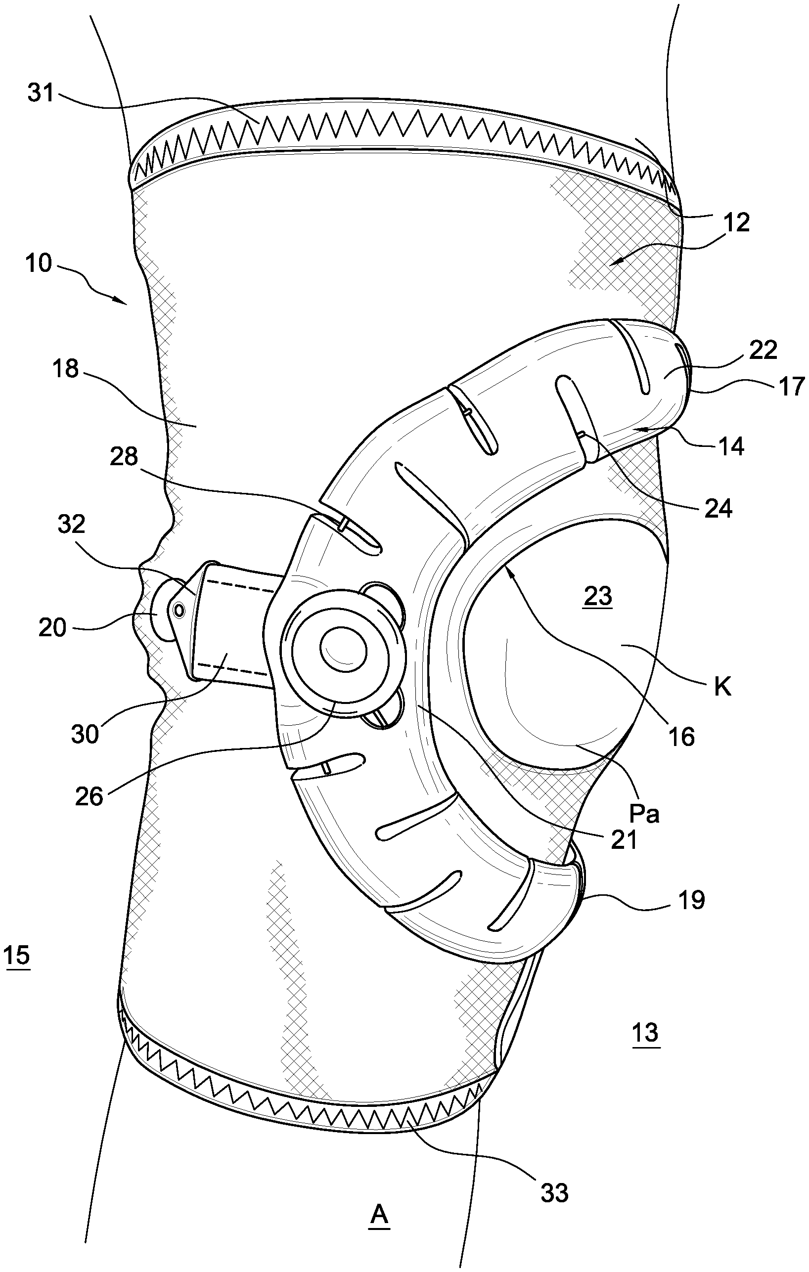
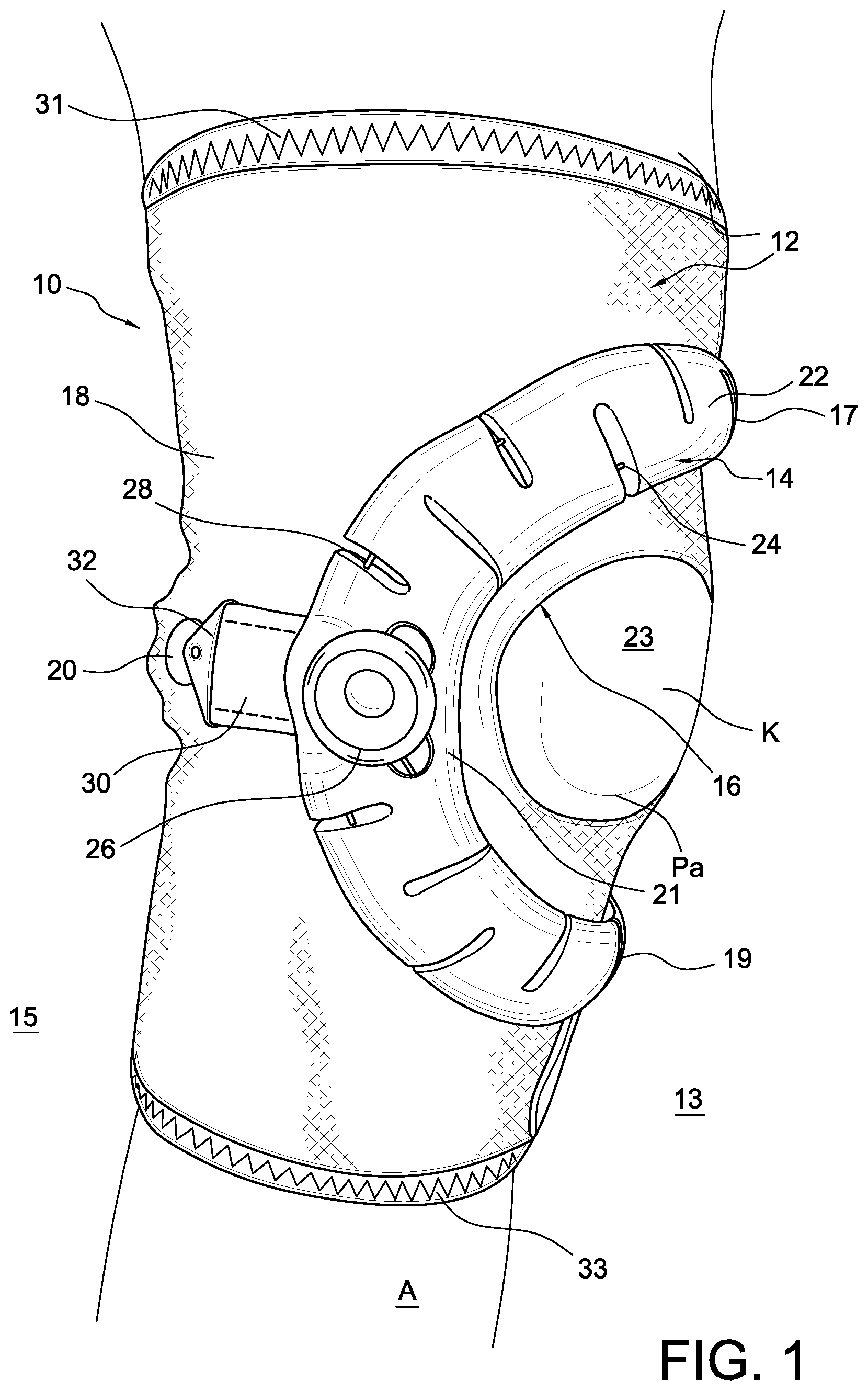
FIG. 1 is a perspective view of one side of a patella device.
FIG. 2 is a perspective view of another side of the patella device of FIG. 1.
FIG. 3A is a plan view of an embodiment of a support in the patella device of FIG. 1.
FIG. 3B is a cross-section taken along lines 3B-3B in FIG. 3A.
FIG. 4 is a detail view of attachment of a middle portion of the support of FIG. 1 to a sleeve.
FIG. 5 is a detail view showing an end portion of a support.
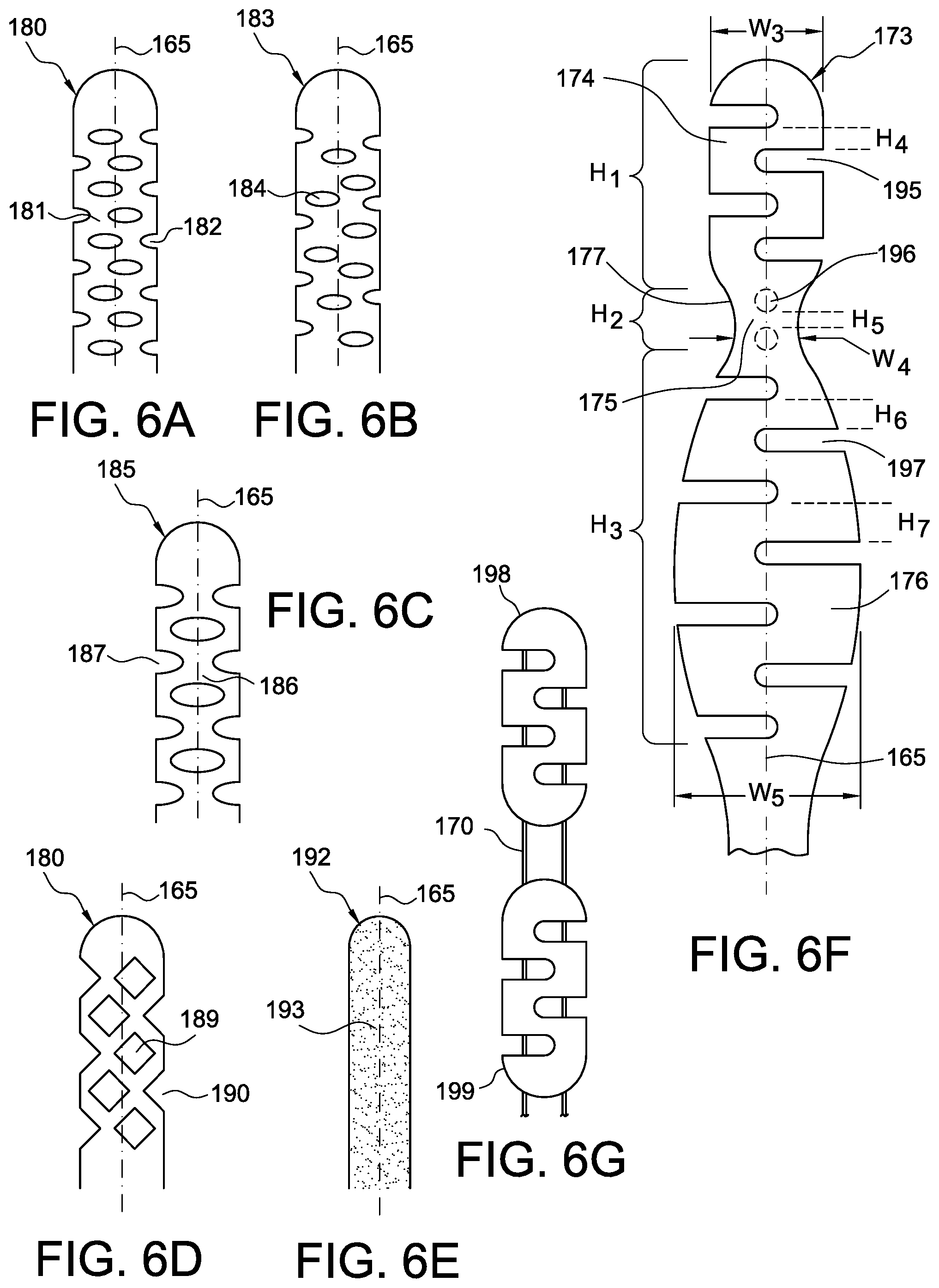
FIGS. 6A-6E are schematic views showing alternative openings in a support or strap.
FIG. 6F is a schematic view showing a variation of a support or strap.
FIG. 6G is a schematic view showing another variation of a support or strap.
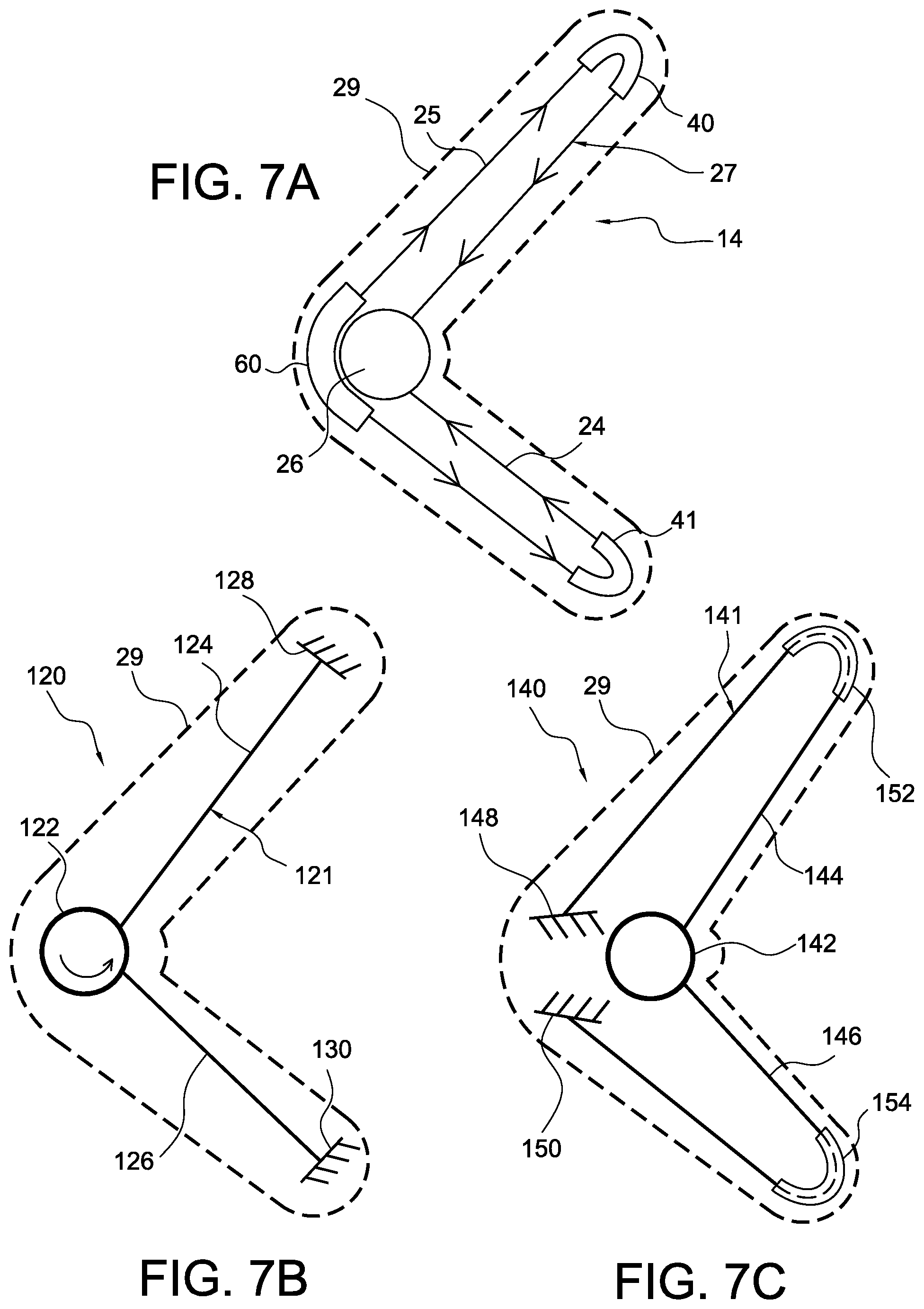
FIG. 7A is a schematic view showing a cable system in the support of FIG. 1.
FIG. 7B is a schematic view showing another cable system.
FIG. 7C is a schematic view showing another cable system.
FIG. 8 is a plan view of another embodiment of a support for the patella device of FIG. 1.
FIG. 9 is a plan view of another embodiment of a support for the patella device of FIG. 1.
FIG. 10 is a plan view of another embodiment of a support for the patella device of FIG. 1.
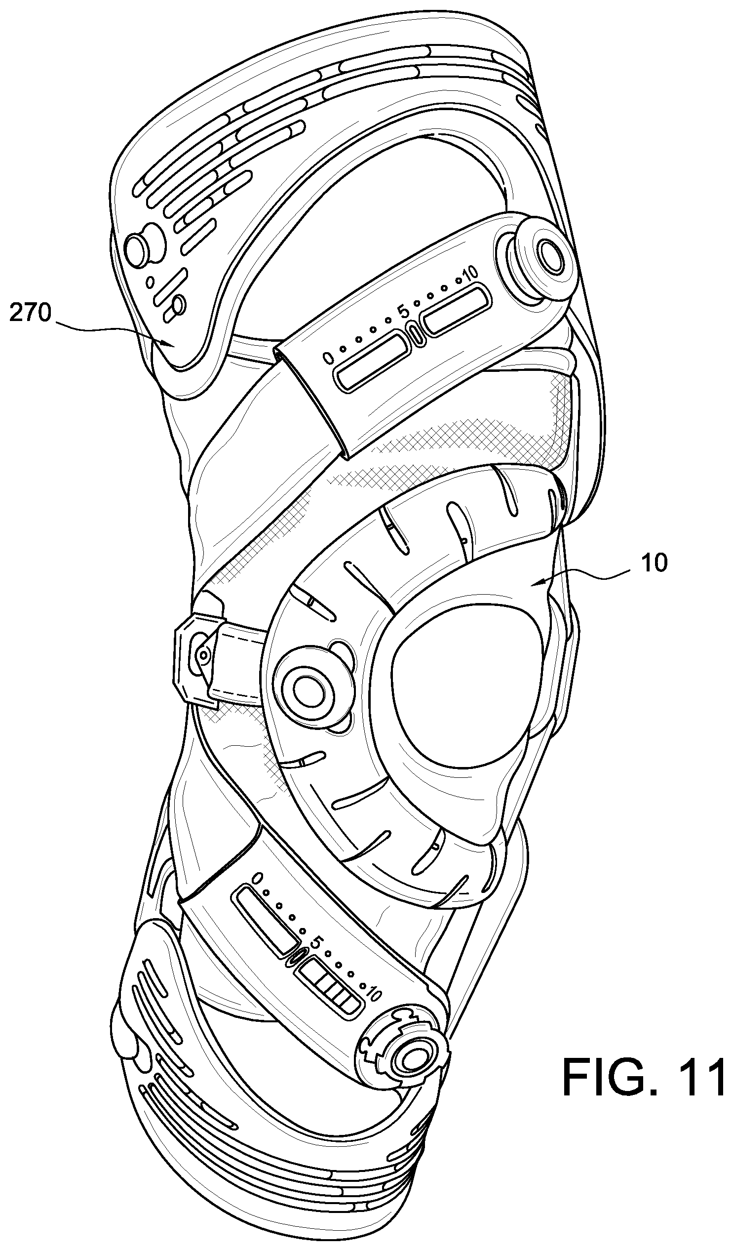
FIG. 11 is a perspective view of the patella device in combination with an orthopedic device.
FIG. 12 is a perspective front view of another embodiment of a patella device.
FIG. 13 is a perspective side view of the patella device of FIG. 12.
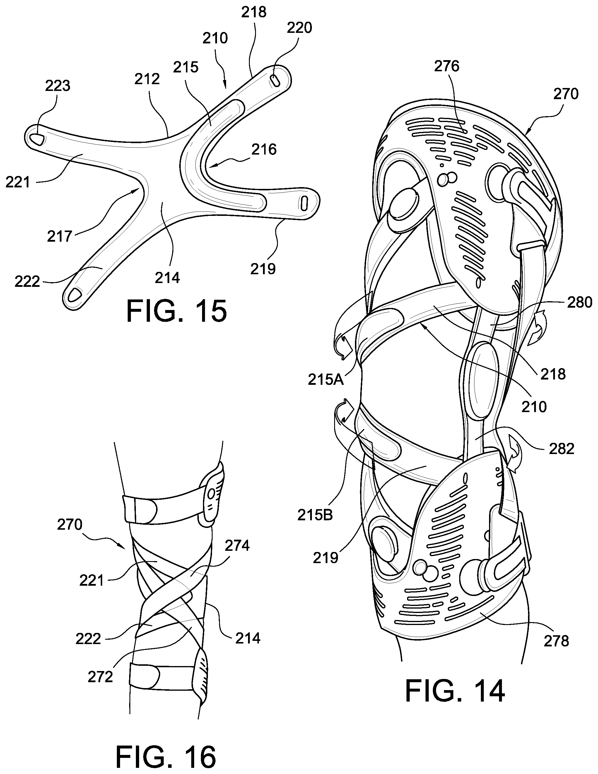
FIG. 14 is a perspective view of another embodiment of a patella device.
FIG. 15 is a perspective front view of the patella device of FIG. 14 in an orthopedic device.
FIG. 16 is a perspective rear view of the patella device of FIG. 15 in the orthopedic device of FIG. 14.
FIG. 17 is a perspective view of an ankle brace having a support.
FIG. 18 is a front view of an ankle brace of FIG. 17.
FIG. 19 is a side view of an ankle brace of FIG. 17.
DETAILED DESCRIPTION OF VARIOUS EMBODIMENTS
A better understanding of different embodiments of the support may be gained from the following description read with the accompanying drawings in which like reference characters refer to like elements.
While the disclosure is susceptible to various modifications and alternative constructions, certain illustrative embodiments are in the drawings and will be described below. It should be understood, however, there is no intention to limit the disclosure to the embodiments disclosed, but on the contrary, the invention covers all modifications, alternative constructions, combinations, and equivalents falling within the spirit and scope of the disclosure and defined by the appended claims.
It will be understood that, unless a term is defined in this disclosure to possess a described meaning, there is no intent to limit the meaning of such term, either expressly or indirectly, beyond its plain or ordinary meaning.
Any element in a claim that does not explicitly state "means for" performing a specified function, or "step for" performing a function, is not to be interpreted as a "means" or "step" clause as specified in 35 U.S.C. .sctn. 112, paragraph 6.
B. Environment and Context of Embodiments
The supports and methods for use herein may be used in various articles including braces, medical devices, clothing, apparel, bags, safety restraints and the like. In a preferred embodiment, the supports and methods are described in connection with orthopedic devices.
Numerous orthopedic devices and components (e.g., subshells and strap retainers) for use therewith are described, with particular focus given to braces and components directed to the knee joint and surrounding areas. The orthopedic device embodiments may serve in protective, preventative or remedial capacities. While the orthopedic device is described within the context of a preferred embodiment directed to securing the knee joint, many of the features described may be extended to orthopedic devices and components that secure other joints and body parts, such as the wrist, elbow, shoulder, ankle and neck.
The orthopedic device embodiments and components for use therewith may be dimensioned to accommodate different types, shapes and sizes of human joints and appendages. In addition, embodiments may be modified to orient principal forces exerted by support systems of the embodiments at any desirable location to secure the brace onto a leg to stabilize the knee.
The knee joint comprises two joints, lateral and medial, between the femur and tibia, and one arthrodial joint between the patella and femur. The primary movements of the knee comprise flexion, i.e., rearward rotational movement of the tibia relative to the femur, and extension, i.e., forward rotational movement of the tibia relative to the femur.
For explanatory purposes, each orthopedic device embodiment or component thereof described may be divided into sections denoted by general anatomical terms for the human body. Such anatomical terms are provided to distinguish various elements of the brace embodiments from one another, but which are not to be considered to limit the invention.
Each of these terms may be used regarding a human leg, which is divided in similar sections with a proximal-distal plane generally extending along the meniscus of the knee between the femur and tibia. The terms "proximal" and "distal" generally refer to locations of the brace that correspond to the location of leg relative to the point of attachment of the leg to the body. The terms "upper" and "lower" may be used in combination with "proximal" and "distal" to connote gradations in-location of "proximal" and "distal." The location where the brace corresponds to the knee joint is used to generally delimit the proximal and distal sections of the brace.
The embodiments of the knee brace can also be considered to fall within "anterior" and "posterior" sections by an anterior-posterior plane. The anterior-posterior plane generally corresponds to the coronal or frontal plane of a human leg, which lies along the central longitudinal axis of a body. A posterior side or element is therefore behind this anterior-posterior plane, whereas an anterior side or element is in front of the anterior-posterior plane.
The terms "inwardly" or "inner" are commonly used to distinguish the side of the brace that may be directed to the posterior side of the brace and specifically adjacent to the leg of the wearer of the brace. Contrariwise, the term "outwardly" or "outer" are used to denote the side of the brace opposite to the inwardly side.
The terms "medial" and "lateral" are relative terms generally understood as indicating location near the midsagittal plane or midline. Therefore, elements located near the midline are referred to as "medial" and those elements further from the midline are "lateral." The term "central" is used to denote the area along the midline of a joint dividing and sharing regions of the medial and lateral regions.
In an embodiment of an orthopedic device, regions of the device may fall within the following quadrants: (I) proximal-medial, (II) distal-medial, (III) distal-lateral, and (IV) proximal-lateral. The posterior section of the brace has the following quadrants: (V) proximal-medial, (VI) distal-medial, (VII) distal-lateral, and (VIII) proximal-lateral. Structural members and features thereof will fall within one of the quadrants is specifically referenced in relation to such quadrant, either in its entirety or partially.
The terms "rigid" and "flexible" are repeatedly used to distinguish characteristics of portions of the brace. The term "rigid" should denote that the frame is devoid of flexibility. Within the context of frame members that are "rigid," it should indicate that they might break if bent with sufficient force. The term "flexible" should denote that features are capable of repeated bending. The term "resilient" is used to qualify such flexible features as generally returning to the initially molded shape with permanent deformation.
The anatomical and characteristic terms described herein are not intended to detract from the normal understanding of such terms as readily understood by one of ordinary skill in the art of orthopedics. The elements of the embodiments described should embrace embodiments that generally correspond to the aforementioned anatomical sections. It is understood that the elements of the brace embodiments described may deviate from falling exactly within the confines of the aforementioned anatomical sections.
C. Various Embodiments
In observing the FIGS. 1 and 2, an embodiment of an orthopedic device is in a patella device 10 for treating a knee K and more particularly a patella Pa of the knee K. The patella device 10 comprises a sleeve 12 defining first and second sides 13, 15 divided by a medial-lateral plane, and a central portion 23 defined along an anterior side "A" of an anterior-posterior plane. A support 14 in the form of a buttress includes a main body 22 having a first end 17 anchored to the first side 13 of the sleeve 12 and a middle portion 21 anchored to the second side of the sleeve 12. The support 14 is located proximate the central portion 23. The central portion 23 may define an opening 16 and the support 14 is arranged to extend across and over the opening 16.
The sleeve 12 is preferably short enabling it to be worn as a stand-alone orthopedic device or in combination with a brace, as depicted in FIG. 7. The sleeve 12 may be constructed from a first section of fabric, such as Lycra, in the anterior area or side, and such fabric may be reinforced to provide rigidity yet is breathable. The posterior area or side may be formed from a second section of fabric, such as Lyrca, that may be thinner or substantially thinner than the first section. The second section is preferably breathable, comfortable permitting each donning and doffing, and a close anatomical fit. The surfaces of the first and second sections preferably have a low friction surface to permit movement of any straps from the orthopedic device.
The support 14 may define an arcuate shape or a C-shape, and is flexible to conform to anatomy of a wearer of the orthopedic device 10. The support 14 is preferably adjustable in length such that a first end 17 of the support 14 includes first and second straps 34, 35 removably securable to a surface of the sleeve 12. The sleeve 12 defines a fastener segment 38 arranged to secure to a corresponding connection feature carried by the first and second straps 34, 35.
The patella device 10 includes first and second flaps 36, 37 each having a first end 39 secured to the sleeve 12 and a second end 41 flexibly extending from the sleeve 12. The second ends 41 are arranged to adjustably secure to an outer surface of the sleeve 12 for adjusting a circumference of the sleeve. The sleeve 12 defines a fastener segment 38 arranged to secure to a corresponding connection feature carried by the first and second straps 34, 35. The second end 41 of the first and second flaps 36, 37 secure to the fastener segment 38.
The flaps 36, 37 may be arranged to secure over and onto the first and second straps 34, 35 and the fastener segment 38. Adjustment of the flaps 36, 37 enable circumferential adjustment of the sleeve to assure it is retained on the leg of the user.
The support 14 may define first and second ends 17, 19 each extending toward the first side 13. The first and second ends 17, 19 have first and second straps 34, 35 securable to the sleeve 12. The middle portion 21 of the support 14 is arranged to resist adjustment of the first and second straps 34, 35. The main body 22 forming the support 14 is preferably formed from a resilient compressible material, such as foam, textile, synthetic or natural rubber, polymer and the like. The elasticity or inelasticity of the material forming the support will depend on the application. In the patella device 10, the support 14 is preferably inelastic to prevent the material of the support from significantly yielding to movement of the user's knee.
The support may vary in width and thickness over its length or cross-section. For example, in FIG. 3A, the portion of the main body 22 of the support 14 about a tensioning device 26 has a greater width W.sub.1 than a width W.sub.2 at end portions of the support near the straps 34, 35. This arrangement is to at least accommodate the tensioning device 26 and provide greater support at this section which hugs or embraces a side of the knee. Of course, the widths of the support may be modified for other applications whereby the widths are not limited to a couple of widths but the width may vary along the width according to intended use of the support and the anatomy or other about it extends.
Referring to the thickness, the thickness of the main body 22 may vary along the length of the support 14 and over its cross-section. For example, FIG. 3B shows how the center portion 72 has a greater thickness T.sub.1 in part to provide greater rigidity and to accommodate channels 70 through which cable segments 24, 25 extend, as discussed in greater detail below. The thickness T.sub.2 at a periphery or edge portions 61, 63 is less than the center portion thickness T.sub.1 to provide pressure relief along the periphery.
The main body 22 may be arranged so different surfaces may have varying contours according to desired areas of support and anatomy or other upon which the support extends. For example, FIG. 3B shows a rounded top surface 74 with varying height as a result of the thickness of the support and pressure relieving properties of the periphery. A bottom surface 76 is preferably flat so as secure fully or mostly against the surface upon which the support extends.
Although exemplary widths, thicknesses and surface contours are described, the support is not limited to the depicted examples, but may include any combination and varying properties taking the examples in consideration.
A stay 18 may be at one or both of the first and second sides 13, 15 and extending between first and second ends 31, 33 of sleeve 12. The stay 18 is preferably within the sleeve 12.
According to an embodiment in FIG. 4, the connection assembly 20 includes a locking member 42 carried by the second end 32 of the third strap 30. An anchoring device 59 is carried by the sleeve 12 and arranged for engagement with the locking member 42. FIG. 4 particularly shows the third strap 30 has a first end securing to the middle portion 21 of the support 14 and a second end 32 forms part of a connection assembly 20 for removably coupling the third strap 30 to the sleeve 12. The third strap 30 is preferably inelastic.
As shown in FIGS. 1-3A, the support 14 defines a preferred pattern of openings including at least one opening 28 formed along the length of the support 14 and extending from a periphery 61, 63 into a width of the support 14. The at least one opening 28 preferably extends past a midline or length adjustment axis 65 of the support from the periphery 61, 63.
The at least one opening 28 may be formed as a slit and define first and second ends 62, 64. The first end 62 may extend past the midline 65 short of a first periphery 61, 63 and the second end 64 is defined by opposed side portions 66, 67 clamped against one another depending on the length of the support 14.
According to the variation in FIG. 3A, the main body 22 defines at least one opening 28 formed along a first periphery 61 and at least one opening 28 formed along a second periphery 63 of the support. The at least one opening 28 is defined by a first set of openings 68 formed along a first periphery 61 and a second set of openings 69 formed along a second periphery 63. The first and second openings 68, 69 alternate relative to one another along a length of the support 14.
The tensioning device 26 is preferably secured to the support 14 so actuation of the tensioning device 26 shortens or lengthens a length of the support 14. The a least one cable segment 24, 25 is linked to the tensioning device 26 and cooperates with the support 14 to adjust the length thereof by actuation of the tensioning device 26. The at least one cable segment 24, 25 extends through the thickness of the support 14 and extends from the first end 17 to a second end 19 opposed to the first end 17 such that actuation of the tensioning device 26 adjusts the length of the at least one cable segment 24, 25 to modify the length of the support 14. The support 14 defines at least one opening 28 through which the at least one cable segment 24, 25 extends.
FIG. 3A illustrates the at least one cable as having first and second cables 24, 25 linked to the tensioning device 26 and cooperating with the support 14 to adjust the length thereof by actuation of the tensioning device 26. The first and second cables 24, 25 are on opposed sides of a midline 65 of the support 14.
Various cable types can be used, including but not limited to stranded steel cable with no coating, stranded steel cable with a polymer coating (e.g., nylon coating), monofilament (e.g., nylon), or other suitable elongate elements. In some embodiments, standard conventional shoe laces or textile cords can be used for the cable.
According to the illustrated embodiments, the tensioning device is configured to incrementally provide or release tension to the cable by tensioning. The tensioning device may correspond to a strap tightener assembly for an orthopedic device according to U.S. application Ser. No. 13/739,491, filed on Jan. 11, 2013 and published as U.S. patent application publication no. 2013/0184628 A1 on Jul. 18, 2013. A variation of the tensioning device is also described in U.S. Pat. No. 7,198,610, granted on Apr. 3, 2007, and U.S. Pat. No. 9,125,730, granted Sep. 8, 2015, which are incorporated herein by reference and belong to the assignee of this disclosure. Commercial examples of a tensioning device that may also be used with different embodiments of the support include the BOA lacing system of BOA Technology Inc. of Steamboat Springs, Colo.
The tensioning device is not limited to dial tensioning or a winding system but may include other ratcheting type systems such as a ladder ratchet strap, as discussed in U.S. Pat. No. 7,198,610. Alternatively, the tensioning device can be simplified as a clasp arranged to disengage from the cables and lockingly engage upon a desired tension in the cable by applying traction or wedging. Examples of clasp or blocking devices are described in U.S. Pat. No. 5,566,474, granted Oct. 22, 1996, U.S. Pat. No. 7,082,652, granted Aug. 1, 2006, U.S. Pat. No. 7,360,282, granted Apr. 22, 2008, each of which are incorporated by reference. From the foregoing, a variety of tensioning devices may be employed in combination with the cable that enable locking of a desired tension in the cable and the selective release of tension of the cable.
FIG. 5 exemplifies another embodiment of an end portion of a support 160 having a similar arrangement to the support 14 in FIG. 3A. The support 160 has a body 166 including first and second patterns of openings 168, 169, along first and second peripheries 161, 162 of the support 160. Each of the openings includes a first end 162 extending past a midline or length adjustment axis 165 extending generally along the midspan of the width of the support 160. A second end 164 is located along one of the peripheries 161, 162. A cable 170 may extend within across the first and second patterns of openings 168,169 to a guide 171 located within or along a surface of the body 166. The body 166 includes a head portion 172 that may be secured directed to an article by suitable fasteners, such as hook-and-loop, buttons, or the like, or may include a strap attached thereto.
In observing FIG. 5, it is preferable that the openings of the first and second patterns overlap one another along the length adjustment axis 165, such that the first ends 162 of the first and second patterns are located along opposed sides of the midline relative to the second ends 164. This arrangement allows the support 160 to both accommodate shape of a surface along which it is located and permits it to shorten or lengthen according to tension adjustment in the cable 170. Length adjustment will occur along the axis of length adjustment 165.
In an alternative, the support may be arranged so that openings do not overlap. While in this alternative the support may not shorten or lengthen according to an increase in tension in the cable, the support can still adapt to a surface along which it is located. A variation of such alternative may include different cables extending along across the openings rather than a cable extending about the guide 171. The cable ends may be anchored at the head portion 172 or other suitable location, and each cable may be adjusted differently so as to create different shape profiles of the first and second peripheries 161, 162.
One of the features the support may have is the overlapping shape described with FIGS. 1-5, so that as cables are adjusted, the support may conform to a surface along which it is located and apply tension thereto. FIGS. 6A-6F depict alternative shape arrangements for the opening patterns, specifically shown as overlapping one another at least to some extent to enable length adjustment of the support.
FIG. 6A shows a support 180 having a pattern of openings in the exemplary form of ellipses 181. At least some of the ellipses overlap 181, particularly along a length adjustment axis 165. The ellipses 181 may occur within peripheries of the support 180, or may be located open along the peripheries as in ellipses 182. The openings may be in an ordered configuration, and are not limited to being in the form of ellipses. The openings may have many shapes providing they enable both shape and length adjustment of the support depending at least one part of adjustment of cables, as described in embodiments herein.
FIG. 6B depicts a support 183 which is a variation of the support 180 in FIG. 6A. The support 183 has random openings 184 in which at least some of the openings overlap one another along the length adjustment axis 165. FIG. 6C shows a support 185 which is another variation of the support 180 in FIG. 6A. The support 185 represents a more narrow width than the support 180, and minimizes the openings 186. A set of openings 186 are generally aligned along the length adjustment axis 165, although openings 187 are located along the peripheries to accommodate shape and length adjustment of the support 185, and yet further openings may be provided.
FIG. 6D depicts a support 188 having a pattern of opening in the exemplary form of a net-type shape whereby the openings are in a predetermined pattern with staggered openings 189 including partial openings 190 along the peripheries of the support 188, but in which the openings 189 overlap at least in part along the length adjustment axis 165.
FIG. 6E shows a support 192 formed from a porous material having openings 193 inherent in the porous material enabling both length and shape adjustment along the length adjustment axis 165. These openings may be micro-holes in an open or closed cell foam such that the micro-holes allow the support to length upon stretching of the support, or collapse upon release of stretching of the support.
FIG. 6F depicts an example of a support 194 having sections 174, 175, 176 with different dimensions. For example, the first section 174 has a height H.sub.1 and width W.sub.3 greater than a second section 175 with a height H.sub.2 and width W.sub.4. In this instance, the second section 175 may be a transitory section of the support providing greater bendability but arranged in an area requiring less support. The first section 174 may transition to the second section 175 by a taper profile 177 to enable gradual diminution of support and increased bendability. The support 194 may have a third section 176 having yet a different height H.sub.3 and width W.sub.6 from the first and second sections 174, 175. Again, any of the sections may be arranged according to desired use of the support, and the support 194 is merely exemplary to show how the support may be modified according to prescribed needs of the support.
The support 194 may likewise have different patterns of openings according to the sections, or may have yet further varying openings within a section itself. The first section 174 is shown with elongate openings 195 generally uniformly spaced apart by height H.sub.4, whereas the second section 175 has circular openings 196 spaced apart by height H.sub.5 which may be different from height H.sub.4. Alternatively, the second section 175 may be devoid of openings so that this region is substantially non-adjustable in height. The third section 176 has openings 197 of differing lengths to cross the length adjustment axis 165, and may be spaced apart differently according to where they are located within the third section 176. For example, some openings are spaced apart by height H.sub.6 whereas other openings are spaced apart by height H.sub.7 which is different from height H.sub.6.
According to the embodiments described herein, a cable system and a tensioning device may be adapted to different configurations. FIGS. 7A-7C exemplify different configurations in which a single or multiple cables are employed and anchored or guided at different locations along the support. While the examples show the support generally having an arcuate or generally perpendicular configuration, the support is not limited to such a shape and may take on the shape of elongate, circular or other shapes.
FIG. 7A shows first and second guides 40, 41 near the first end of the support 14 for redirecting the first and second cable segments 24, 25 of at least one cable 27 to the tensioning device 26. A guide 60 is along a side of the tensioning device 26 and arranged to route the first and second cable segments 24, 25. According to this embodiment, the first and second segments 24, 25 will adjust dependent of one another because of the cable 27. Because the cable 27 "doubles back" at the far ends or at the guides 40, 41 of the support, a doubling effect on the force is generated on the cable 27, similar to a pulley system.
FIG. 7B depicts another cable configuration 120 whereby the cable 121 does not double back as in FIG. 7A. In this configuration, first and second cable segments 124, 126 are independently adjusted by the tensioning device 122 from one another such that the first and second cable segments 124, 126 terminate at first and second anchors 128, 130.
FIG. 7C illustrates another cable configuration 140 in that the cable 141 has first and second cable segments 144, 146 which couple to a tensioning device 142, and terminate and secure to anchors 148, 150. The anchors 148, 150 may be proximate to the tensioning device 142, and the first and second cable segments 144, 146 extend about guides 152, 154 so the cable "doubles back." In this configuration, while there is a doubling of the force generate when the cable 141 is tensioned, the first and second cable segments are generally independent of one another.
In any of the cable configurations, the tensioning device is not limited to being centrally located along the cable configuration but may be located so the initial lengths of the first and second cable segments are disproportionate relative to one another to achieve different contouring and tensioning of each of the first and second cable segments. By placing the tensioning device generally in the middle of the cable configuration, the support may probably have a generally uniform contraction. Alternatively, by disproportionately placing the tensioning device in the cable configuration, there may be non-uniform contraction so the shape of the support may contort.
The cable configuration is not limited to a single tensioning device, however it is envisioned that multiple cables may be employed that are respectively tensioned independently from one another by their own or shared tensioning devices. Additionally, while the cable configurations schematically show the cable as generally linearly extending through or relative to the body of the support, the cable may be arranged so that it alternates between opposed sides of the length adjustment axis, either terminating at an anchor or returning toward or to the tensioning device much like lacing of shoes.
While the cable is described as extending through the body of the support in certain embodiments, it may be located along at least one of the surfaces of the body with external guides channeling the course of the cable. Alternatively, the support body may define channels within the thickness of the body through which the cable extends. Essentially, the cable configuration is arranged so that adjusting a length of the cable relative to the support enables length adjustment and/or shape contouring of the support, whether the cable is internally or externally mounted relative to the support.
From these cable configurations and the aforementioned embodiments, a method for adjusting a length involves adjusting tension in the at least one cable or cable segments by regulating the tensioning device and causing geometry of the at least one opening to modify according to tension in the cable. Ends of the support are preferably anchored at first and second locations such that the length of the support adjusts along the length adjustment axis according to regulation of the tensioning device. By providing at least one peripheral opening along a periphery of the support, the shape of the support may be contoured according to regulation of the tensioning device by modifying a geometry of the peripheral opening as a result in adjustment of tension in the at least one cable.
FIG. 8 illustrates another embodiment of a support 300 having a main body 302 generally forming a circular or oval profile, particularly an opening 329 for securing about a patella as in FIG. 1. For example, the inner profile 330 of the main body 302 is circular, and the outer profile 328 is generally in a tear drop shape such that a first end 324 is tapered whereas a second end 326 is rounded. The tear drop shape caters to the first and second straps 312, 314 located at the first end 324 to facilitate securing to the sleeve, as in FIG. 1. The rounded shape at the second end 326 is arranged to accommodate the tensioning device 304 and the third strap 306.
As with the embodiment of FIGS. 1-4, the third strap 306 includes an anchor 308 and a locking member 310 such as a pin or other connector to the sleeve. One or multiple cables 316, 318 may be included in the main body 302 and coupled to the tensioning device 304.
The shape of the main body 302 may vary depending on the tension of the cables 316, 318 such that the opening 329 may be elongate, whereas reducing the tension will cause the opening 329 to reflect a more circular profile. As with the embodiment of FIGS. 1 and 2, the at least one opening in the form of slits 320, 322 may open or close to accommodate the shape of the support depending on the displacement of the cables 316, 318. The first and second ends 324, 326 are preferably devoid of the slits 320, 322 to reinforce the straps and serve as anchor portions of the main body 302 counteracting tension or securement of the straps.
FIG. 9 shows an alternative embodiment of a support 80. The support 80 includes an elongate body 82 defining a first end 81 including a connection assembly 88 for securing to the sleeve 12. A second end is bifurcated into first and second portions 90, 92 each carrying a strap 84, 86 arranged to secure to the sleeve 12 of FIGS. 1 and 2. The elongate body 82 is preferably elastic and extends over the opening 23 of the sleeve to secure the patella.
In this embodiment, a rear surface of the elongate body 82 may include silicone to assist in maintaining the support 80 in position over the knee. The strap is particularly used to exert a downward force on the patella and a lateral to medial pull. As with any of the embodiments, the connection assembly 88 may be secured to the elongate body 82 by stitching 44 extending through a plurality of apertures 46 formed by the connection assembly 88.
FIG. 10 is another embodiment illustrating a support 400. The support 400 includes first and second portions 402, 404 extending from a main portion 403. The support 400 generally forms a U-shape subject to deformation according to actual use of the support. The first and second portions 402, 404 include fastener tabs 406, 408 for securing to the sleeve 12. A connection assembly 411 secures to the main portion 403 and includes a strap 410 and an anchor 412 with a locking member 414 for connecting to the sleeve similarly to the embodiment of FIG. 1.
FIG. 11 shows the patella device 10 in use with an orthopedic device 270. Although other orthopedic devices are envisioned, an example of a suitable orthopedic device may be found in U.S. Pat. No. 7,198,610.
FIGS. 12 and 13 illustrate an alternate embodiment of a patella device 100. The patella device 100 includes a sleeve 102 arranged to secure over a user's leg similarly arranged as the embodiment of FIG. 1. The support 114 is covered by a covering 115 adapted to accommodate movement of the support as it expands or contracts due to tensioning of cables therein, as in the embodiment of FIG. 1. FIG. 13 shows how a hinge 121 and corresponding struts 119 may be located within or concealed by the sleeve 112 by a covering 118.
FIGS. 14-16 depict another alternate embodiment of a patella device 210 for use with an unloading brace 270 with a strap assembly having dynamic force straps 272, 274. The patella device 210 includes a main body 212 defining a central portion 214 and first and second side portions 216, 217. The first side portion 216 includes bifurcated first and second extensions 218, 219. A support 215 secures to the first side 216 and extends along the first and second extensions 218, 219.
The first and second extensions 218, 219 include connection elements 220 for securing to the orthopedic device 270 at frame supports 276, 278 spaced apart by struts 280, 282. The second side portion 217 includes bifurcated first and second extensions 221, 222. The first and second extensions 221, 222 of the second side 217 include connection elements 223, and may extend over or underneath the strap assembly 272, 274 supported by the unloading device 270.
Referring to FIGS. 17 to 19, an ankle brace 500 is arranged with an ankle support 502 attached to an ankle brace 510 adapted for adjusting an angle of a user's ankle for inversion and eversion control of an ankle. The brace 500 includes a foot plate or foot portion 512 and an upper portion 510 connectable above a user's ankle. The support 502 is located between or at the upper portion 510 and the foot plate 512. The support 502 has openings 506 and is adjustable by a tensioning device 504 secured to a cable 508 in a manner according to any of the aforementioned configurations. A distance 514 of the support 502 between the upper portion 510 and the foot plate 512 is adjustable in length and angle according to adjustment of the tensioning device.
The support may be constructed of a material that is substantially rigid or becomes sufficiently rigid to place and maintain an ankle in a desired eversion or inversion configuration according adjustment by the tensioning device. The support may be sufficiently compressible to enable comfort to the user's ankle as the support is adjusted. The shape or geometry of the support may be adapted for contouring to a user's ankle such in the illustrated example whereby the width of the support tapers from the foot plate to the upper portion.
The embodiments of the support described above in accordance with the present disclosure reduce pain, speed healing processes, and impart improved stability and mobility in numerous indications. In an orthopedic device, for example, the support permits more precise adjustment and enables efficient coordination between a medical professional and the wearer on the degree the orthopedic device should be configured. Patient comfort is also enhanced and donning and doffing of the orthopedic device is eased with the novel features described.
It is to be understood that not necessarily all such objects or advantages may be achieved under any embodiment of the disclosure. Those skilled in the art will recognize that the support, either by itself or combined with another article such as an orthopedic device, may be embodied or carried out in a manner that achieves or optimizes one advantage or group of advantages as taught without achieving other objects or advantages as taught or suggested.
The skilled artisan will recognize the interchangeability of various features from different embodiments. Besides the variations described, other known equivalents for each feature can be mixed and matched by one of ordinary skill in this art to construct a support or an orthopedic device under principles of the present disclosure.
Although the support has been disclosed in certain preferred embodiments and examples, it therefore will be understood by those skilled in the art that the present invention extends beyond the specifically disclosed embodiments to other alternative embodiments and/or uses of the support and obvious modifications and equivalents thereof. It is intended that the present disclosure should not be limited by the particular disclosed embodiments described above.
* * * * *
References
D00000
D00001
D00002
D00003
D00004
D00005
D00006
D00007
D00008
D00009
D00010
D00011
D00012
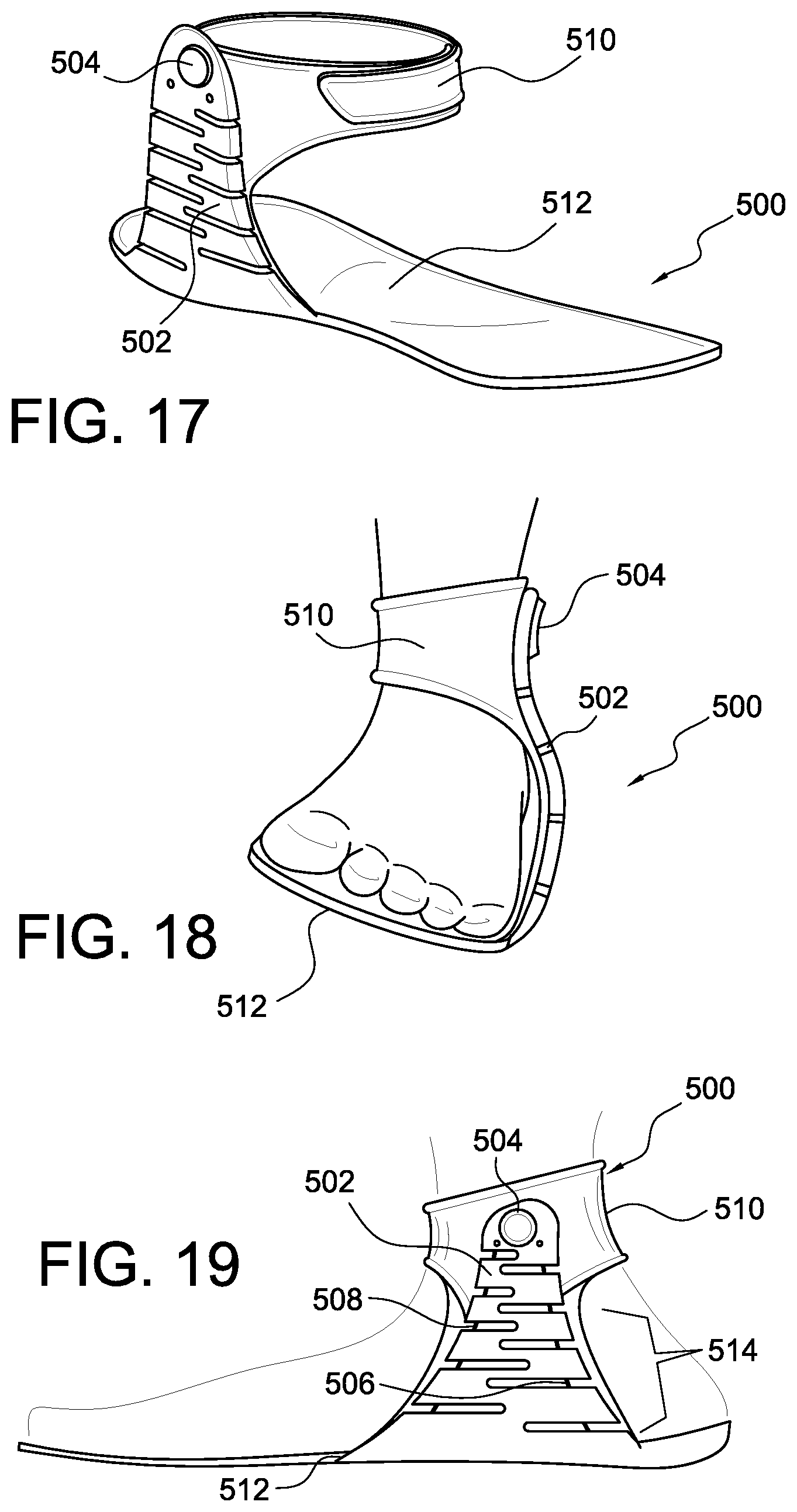
XML
uspto.report is an independent third-party trademark research tool that is not affiliated, endorsed, or sponsored by the United States Patent and Trademark Office (USPTO) or any other governmental organization. The information provided by uspto.report is based on publicly available data at the time of writing and is intended for informational purposes only.
While we strive to provide accurate and up-to-date information, we do not guarantee the accuracy, completeness, reliability, or suitability of the information displayed on this site. The use of this site is at your own risk. Any reliance you place on such information is therefore strictly at your own risk.
All official trademark data, including owner information, should be verified by visiting the official USPTO website at www.uspto.gov. This site is not intended to replace professional legal advice and should not be used as a substitute for consulting with a legal professional who is knowledgeable about trademark law.