Bone tie methods
Blain , et al. April 19, 2
U.S. patent number 11,304,733 [Application Number 17/174,032] was granted by the patent office on 2022-04-19 for bone tie methods. This patent grant is currently assigned to Spinal Elements, Inc.. The grantee listed for this patent is Spinal Elements, Inc.. Invention is credited to Jason Blain, Gregory Thomas Bradford, Taylor Semingson.


View All Diagrams
| United States Patent | 11,304,733 |
| Blain , et al. | April 19, 2022 |
Bone tie methods
Abstract
Various embodiments of bone ties, bone tie inserters, and methods for treating the spine are provided. The methods can include wrapping the bone tie around transverse processes of adjacent vertebrae to correct coronal plane deformity. The methods can include wrapping the bone tie around the spinous process of one vertebra and around the transverse process of a second adjacent vertebra to achieve rotational correction. The methods can include wrapping the bone tie around the lamina of adjacent vertebrae to achieve sagittal correction. The methods can include applying tension to the bone tie to set the sagittal correction. The methods can include passing the bone tie through a lumen in a vertebral body or a pedicle of the inferior vertebra and the lamina or articular process of the superior vertebra.
| Inventors: | Blain; Jason (Encinitas, CA), Semingson; Taylor (San Diego, CA), Bradford; Gregory Thomas (Carlsbad, CA) | ||||||||||
|---|---|---|---|---|---|---|---|---|---|---|---|
| Applicant: |
|
||||||||||
| Assignee: | Spinal Elements, Inc.
(Carlsbad, CA) |
||||||||||
| Family ID: | 1000006248634 | ||||||||||
| Appl. No.: | 17/174,032 | ||||||||||
| Filed: | February 11, 2021 |
Prior Publication Data
| Document Identifier | Publication Date | |
|---|---|---|
| US 20210251667 A1 | Aug 19, 2021 | |
Related U.S. Patent Documents
| Application Number | Filing Date | Patent Number | Issue Date | ||
|---|---|---|---|---|---|
| 62976596 | Feb 14, 2020 | ||||
| Current U.S. Class: | 1/1 |
| Current CPC Class: | A61B 17/7053 (20130101); A61B 2017/00407 (20130101); A61B 2017/564 (20130101); A61B 17/7083 (20130101); A61F 2/4455 (20130101) |
| Current International Class: | A61B 17/70 (20060101); A61B 17/56 (20060101); A61F 2/44 (20060101); A61B 17/00 (20060101) |
References Cited [Referenced By]
U.S. Patent Documents
| 86016 | January 1869 | Howell |
| 1630239 | May 1927 | Binkley et al. |
| 1822280 | September 1931 | Ervay |
| 1822330 | September 1931 | Anslie |
| 2486303 | October 1949 | Longfellow |
| 2706023 | April 1955 | Merritt |
| 2967282 | January 1961 | Schwartz et al. |
| 3111945 | November 1963 | Von Solbrig |
| 3149808 | September 1964 | Weckesser |
| 3570497 | March 1971 | Lemole |
| 3867728 | February 1975 | Stubstad et al. |
| 3875595 | April 1975 | Froning |
| 3879767 | April 1975 | Stubstad |
| 4001896 | January 1977 | Arkangel |
| 4037603 | July 1977 | Wendorff |
| 4085466 | April 1978 | Goodfellow et al. |
| 4119091 | October 1978 | Partridge |
| 4156296 | May 1979 | Johnson et al. |
| 4164793 | August 1979 | Swanson |
| 4166292 | September 1979 | Bokros |
| 4231121 | November 1980 | Lewis |
| D261935 | November 1981 | Halloran |
| 4312337 | January 1982 | Donohue |
| 4323217 | April 1982 | Dochterman |
| 4349921 | September 1982 | Kuntz |
| 4502161 | March 1985 | Wall |
| D279502 | July 1985 | Halloran |
| D279503 | July 1985 | Halloran |
| 4535764 | August 1985 | Ebert |
| 4570618 | February 1986 | Wu |
| 4573458 | March 1986 | Lower |
| 4573459 | March 1986 | Litton |
| 4634445 | January 1987 | Helal |
| 4643178 | February 1987 | Nastari |
| 4662371 | May 1987 | Whipple et al. |
| 4706659 | November 1987 | Matthews et al. |
| 4714469 | December 1987 | Kenna |
| 4722331 | February 1988 | Fox |
| 4730615 | March 1988 | Sutherland et al. |
| 4759766 | July 1988 | Buettner-Janz et al. |
| 4759769 | July 1988 | Hedman et al. |
| 4772287 | September 1988 | Ray et al. |
| 4773402 | September 1988 | Asher et al. |
| 4834757 | May 1989 | Brantigan |
| 4863477 | September 1989 | Monson |
| 4880429 | November 1989 | Stone |
| 4904260 | February 1990 | Ray et al. |
| 4907577 | March 1990 | Wu |
| 4911718 | March 1990 | Lee et al. |
| 4919667 | April 1990 | Richmond |
| 4923471 | May 1990 | Morgan |
| 4936848 | June 1990 | Bagby |
| 4941466 | July 1990 | Romano |
| 4955913 | September 1990 | Robinson |
| 4959065 | September 1990 | Arnett et al. |
| 4969909 | November 1990 | Barouk |
| 5000165 | March 1991 | Watanabe |
| 5002546 | March 1991 | Romano |
| 5011484 | April 1991 | Breard |
| 5015255 | May 1991 | Kuslich |
| 5047055 | September 1991 | Bao et al. |
| 5062845 | November 1991 | Kuslich |
| 5071437 | December 1991 | Steffee |
| 5092866 | March 1992 | Breard et al. |
| 5092868 | March 1992 | Mehdian |
| 5112013 | May 1992 | Tolbert et al. |
| 5112346 | May 1992 | Hiltebrandt et al. |
| 5127912 | July 1992 | Ray et al. |
| 5135188 | August 1992 | Anderson et al. |
| 5147404 | September 1992 | Downey |
| 5171280 | December 1992 | Baumgartner |
| 5192326 | March 1993 | Bao et al. |
| 5192327 | March 1993 | Brantigan |
| 5209755 | May 1993 | Abrahan et al. |
| 5258031 | November 1993 | Salib et al. |
| 5282861 | February 1994 | Kaplan |
| 5286249 | February 1994 | Thibodaux |
| 5300073 | April 1994 | Ray et al. |
| 5304178 | April 1994 | Stahurski |
| 5306275 | April 1994 | Bryan |
| 5306308 | April 1994 | Gross et al. |
| 5306309 | April 1994 | Wagner et al. |
| 5326364 | July 1994 | Clift, Jr. et al. |
| 5330479 | July 1994 | Whitmore |
| 5360431 | November 1994 | Puno et al. |
| 5368596 | November 1994 | Burkhart |
| 5370697 | December 1994 | Baumgartner |
| 5372598 | December 1994 | Luhr et al. |
| 5400784 | March 1995 | Durand et al. |
| 5401269 | March 1995 | Buttner-Janz et al. |
| 5413576 | May 1995 | Rivard |
| 5415661 | May 1995 | Holmes |
| 5425773 | June 1995 | Boyd et al. |
| 5437672 | August 1995 | Alleyne |
| 5445639 | August 1995 | Kuslich et al. |
| 5458642 | October 1995 | Beer et al. |
| 5458643 | October 1995 | Oka et al. |
| 5462542 | October 1995 | Alesi, Jr. |
| 5487756 | January 1996 | Kallesoe et al. |
| 5491882 | February 1996 | Walston et al. |
| 5496142 | March 1996 | Fodor et al. |
| 5496318 | March 1996 | Howland et al. |
| 5507823 | April 1996 | Walston et al. |
| 5509918 | April 1996 | Romano |
| 5514180 | May 1996 | Heggeness et al. |
| 5527312 | June 1996 | Ray |
| 5527314 | June 1996 | Brumfield et al. |
| 5534028 | July 1996 | Bao et al. |
| 5534030 | July 1996 | Navarro et al. |
| 5540698 | July 1996 | Preissman |
| 5540703 | July 1996 | Barker, Jr. |
| 5540706 | July 1996 | Aust et al. |
| 5545229 | August 1996 | Parsons et al. |
| 5549619 | August 1996 | Peters et al. |
| 5556431 | September 1996 | Buttner-Janz |
| 5562738 | October 1996 | Boyd et al. |
| 5571105 | November 1996 | Gundolf |
| 5571131 | November 1996 | Ek et al. |
| 5571189 | November 1996 | Kuslich |
| 5571191 | November 1996 | Fitz |
| 5577995 | November 1996 | Walker et al. |
| 5586989 | December 1996 | Bray, Jr. |
| 5591165 | January 1997 | Jackson |
| 5603713 | February 1997 | Aust et al. |
| 5638700 | June 1997 | Shechter |
| 5645597 | July 1997 | Krapiva |
| 5645599 | July 1997 | Samani |
| 5649947 | July 1997 | Auerbach et al. |
| 5653762 | August 1997 | Pisharodi |
| 5674295 | October 1997 | Ray et al. |
| 5674296 | October 1997 | Bryan et al. |
| 5676701 | October 1997 | Yuan et al. |
| 5683464 | November 1997 | Wagner et al. |
| 5683466 | November 1997 | Vitale |
| 5700265 | December 1997 | Romano |
| 5702450 | December 1997 | Bisserie |
| 5707373 | January 1998 | Sevrain et al. |
| 5713542 | February 1998 | Benoit |
| 5716415 | February 1998 | Steffee |
| 5725582 | March 1998 | Bevan |
| 5741260 | April 1998 | Songer et al. |
| 5741261 | April 1998 | Moskovitz et al. |
| D395138 | June 1998 | Ohata |
| 5766251 | June 1998 | Koshino |
| 5766253 | June 1998 | Brosnahan |
| 5772663 | June 1998 | Whiteside et al. |
| 5797916 | August 1998 | McDowell |
| 5810854 | September 1998 | Beach |
| 5824093 | October 1998 | Ray et al. |
| 5824094 | October 1998 | Serhan et al. |
| 5836948 | November 1998 | Zucherman et al. |
| 5851208 | December 1998 | Trott |
| 5860977 | January 1999 | Zucherman et al. |
| 5865846 | February 1999 | Bryan et al. |
| 5868745 | February 1999 | Alleyne |
| 5876404 | March 1999 | Zucherman et al. |
| 5879396 | March 1999 | Walston et al. |
| 5888203 | March 1999 | Goldberg |
| 5893889 | April 1999 | Harrington |
| 5895428 | April 1999 | Berry |
| RE36221 | June 1999 | Breard et al. |
| 5918604 | July 1999 | Whelan |
| 5951555 | September 1999 | Rehak et al. |
| 5964765 | October 1999 | Fenton et al. |
| 5993452 | November 1999 | Vandewalle |
| 5997542 | December 1999 | Burke |
| 6001130 | December 1999 | Bryan et al. |
| 6014588 | January 2000 | Fitz |
| 6019763 | February 2000 | Nakamura et al. |
| 6019792 | February 2000 | Cauthen |
| 6039763 | March 2000 | Shelokov |
| 6048342 | April 2000 | Zucherman et al. |
| 6050998 | April 2000 | Fletcher |
| 6063121 | May 2000 | Xavier et al. |
| 6066325 | May 2000 | Wallace et al. |
| 6068630 | May 2000 | Zucherman et al. |
| RE36758 | June 2000 | Fitz |
| 6080157 | June 2000 | Cathro et al. |
| 6099531 | August 2000 | Bonutti |
| 6102347 | August 2000 | Benoit |
| 6106558 | August 2000 | Picha |
| 6113637 | September 2000 | Gill et al. |
| 6132464 | October 2000 | Martin |
| 6132465 | October 2000 | Ray et al. |
| 6146422 | November 2000 | Lawson |
| 6156067 | December 2000 | Bryan et al. |
| 6179839 | January 2001 | Weiss et al. |
| D439340 | March 2001 | Michelson |
| 6200322 | March 2001 | Branch et al. |
| 6293949 | September 2001 | Justis et al. |
| D450122 | November 2001 | Michelson |
| 6325803 | December 2001 | Schumacher et al. |
| D454953 | March 2002 | Michelson |
| 6368325 | April 2002 | McKinley et al. |
| 6368350 | April 2002 | Erickson et al. |
| 6371958 | April 2002 | Overaker |
| 6375573 | April 2002 | Romano |
| 6379386 | April 2002 | Resch et al. |
| 6409765 | June 2002 | Bianchi et al. |
| D460188 | July 2002 | Michelson |
| D460189 | July 2002 | Michelson |
| 6419678 | July 2002 | Asfora |
| 6419703 | July 2002 | Fallin et al. |
| 6423071 | July 2002 | Lawson |
| 6436099 | August 2002 | Drewry et al. |
| 6436101 | August 2002 | Hamada et al. |
| 6436146 | August 2002 | Hassler et al. |
| D463560 | September 2002 | Michelson |
| 6447544 | September 2002 | Michelson |
| 6470207 | October 2002 | Simon et al. |
| 6475220 | November 2002 | Whiteside |
| 6565605 | May 2003 | Goble et al. |
| 6572617 | June 2003 | Senegas |
| 6579318 | June 2003 | Varga et al. |
| 6579319 | June 2003 | Goble et al. |
| 6589244 | July 2003 | Sevrain et al. |
| 6600956 | July 2003 | Maschino et al. |
| 6607530 | August 2003 | Carl et al. |
| 6610091 | August 2003 | Reiley |
| D479331 | September 2003 | Pike et al. |
| 6626944 | September 2003 | Taylor |
| 6641614 | November 2003 | Wagner et al. |
| 6656178 | December 2003 | Veldhuizen et al. |
| 6656195 | December 2003 | Peters et al. |
| 6669697 | December 2003 | Pisharodi |
| 6669729 | December 2003 | Chin |
| 6679914 | January 2004 | Gabbay |
| 6706068 | March 2004 | Ferree |
| 6743232 | June 2004 | Overaker et al. |
| 6761720 | July 2004 | Senegas |
| 6764491 | July 2004 | Frey et al. |
| 6770095 | August 2004 | Grinberg et al. |
| 6783527 | August 2004 | Drewry et al. |
| 6790210 | September 2004 | Cragg et al. |
| 6802863 | October 2004 | Lawson et al. |
| 6811567 | November 2004 | Reiley |
| 6902566 | June 2005 | Zucherman et al. |
| 6908484 | June 2005 | Zubok et al. |
| 6966930 | November 2005 | Arnin et al. |
| 6974478 | December 2005 | Reiley et al. |
| 6974479 | December 2005 | Trieu |
| 7004971 | February 2006 | Serhan et al. |
| D517404 | March 2006 | Schluter |
| 7008429 | March 2006 | Golobek |
| 7013675 | March 2006 | Marquez-Pickering |
| 7051451 | May 2006 | Augostino et al. |
| 7074238 | July 2006 | Stinson et al. |
| 7101375 | September 2006 | Zucherman et al. |
| 7223269 | May 2007 | Chappuis |
| D565180 | March 2008 | Schluter |
| 7371238 | May 2008 | Sololeski et al. |
| 7458981 | December 2008 | Fielding et al. |
| 7517358 | April 2009 | Petersen |
| 7537611 | May 2009 | Lee |
| 7559940 | July 2009 | McGuire et al. |
| 7563286 | July 2009 | Gerber et al. |
| 7585300 | September 2009 | Cha |
| 7608104 | October 2009 | Yuan et al. |
| 7695472 | April 2010 | Young |
| 7799077 | September 2010 | Lang et al. |
| 7806895 | October 2010 | Weier et al. |
| 7846183 | December 2010 | Blain |
| 7862590 | January 2011 | Lim et al. |
| 7935136 | May 2011 | Alamin et al. |
| D643121 | August 2011 | Milford et al. |
| 7993370 | August 2011 | Jahng |
| 7998172 | August 2011 | Blain |
| 8052728 | November 2011 | Hestad |
| 8109971 | February 2012 | Hale |
| 8133225 | March 2012 | Pieske |
| 8163016 | April 2012 | Linares |
| 8172877 | May 2012 | Winslow et al. |
| 8177810 | May 2012 | Ferree |
| 8192468 | June 2012 | Biedermann et al. |
| 8216275 | July 2012 | Fielding et al. |
| 8231661 | July 2012 | Carls |
| 8246655 | August 2012 | Jackson et al. |
| 8267966 | September 2012 | McCormack et al. |
| 8292954 | October 2012 | Robinson et al. |
| 8306307 | November 2012 | Koike et al. |
| 8382801 | February 2013 | Lamborne et al. |
| 8394125 | March 2013 | Assell |
| 8460346 | June 2013 | Ralph et al. |
| 8486078 | July 2013 | Carl et al. |
| 8496691 | July 2013 | Blain |
| 8579903 | November 2013 | Carl |
| 8652137 | February 2014 | Blain et al. |
| 8740942 | June 2014 | Blain |
| 8740949 | June 2014 | Blain |
| 8753345 | June 2014 | McCormack et al. |
| 8784423 | July 2014 | Kowarsch et al. |
| 8858597 | October 2014 | Blain |
| 8882804 | November 2014 | Blain |
| 8961613 | February 2015 | Assell et al. |
| D724733 | March 2015 | Blain et al. |
| 8974456 | March 2015 | Allen et al. |
| 8979529 | March 2015 | Marcus |
| 8992533 | March 2015 | Blain et al. |
| 8998953 | April 2015 | Blain |
| 9017389 | April 2015 | Assell et al. |
| 9060787 | June 2015 | Blain et al. |
| 9101410 | August 2015 | Urrea |
| D739935 | September 2015 | Blain et al. |
| 9149283 | October 2015 | Assell et al. |
| 9161763 | October 2015 | Assell et al. |
| 9179943 | November 2015 | Blain |
| 9220547 | December 2015 | Blain et al. |
| D748262 | January 2016 | Blain |
| 9233006 | January 2016 | Assell et al. |
| D748793 | February 2016 | Blain |
| 9265546 | February 2016 | Blain |
| 9271765 | March 2016 | Blain |
| 9301786 | April 2016 | Blain |
| 9314277 | April 2016 | Assell et al. |
| 9345488 | May 2016 | Assell et al. |
| 9421044 | August 2016 | Blain et al. |
| D765853 | September 2016 | Blain et al. |
| D765854 | September 2016 | Blain et al. |
| 9439686 | September 2016 | Rooney et al. |
| 9456855 | October 2016 | Blain et al. |
| 9517077 | December 2016 | Blain et al. |
| D777921 | January 2017 | Blain et al. |
| D780315 | February 2017 | Blain et al. |
| 9572602 | February 2017 | Blain et al. |
| 9615861 | April 2017 | Perez-Cruet et al. |
| D790062 | June 2017 | Blain et al. |
| 9675387 | June 2017 | Blain |
| 9743937 | August 2017 | Blain et al. |
| 9808294 | November 2017 | Blain |
| 9820784 | November 2017 | Blain et al. |
| 9839450 | December 2017 | Blain et al. |
| D810942 | February 2018 | Blain et al. |
| D812754 | March 2018 | Blain et al. |
| 9936984 | April 2018 | Blain |
| 10022161 | July 2018 | Blain |
| 10085776 | October 2018 | Blain |
| D834194 | November 2018 | Blain et al. |
| 10194955 | February 2019 | Blain et al. |
| 10251679 | April 2019 | Blain et al. |
| D857900 | August 2019 | Blain et al. |
| 10368921 | August 2019 | Blain |
| 10426524 | October 2019 | Blain |
| 10624680 | April 2020 | Blain |
| D884896 | May 2020 | Blain et al. |
| 10758361 | September 2020 | Blain |
| D926982 | August 2021 | Blain et al. |
| 2001/0018614 | August 2001 | Bianchi |
| 2002/0018799 | February 2002 | Spector et al. |
| 2002/0019637 | February 2002 | Frey et al. |
| 2002/0029039 | March 2002 | Zucherman et al. |
| 2002/0040227 | April 2002 | Harari |
| 2002/0065557 | May 2002 | Goble et al. |
| 2002/0072800 | June 2002 | Goble et al. |
| 2002/0077700 | June 2002 | Varga et al. |
| 2002/0086047 | July 2002 | Mueller et al. |
| 2002/0120335 | August 2002 | Angelucci et al. |
| 2002/0123806 | September 2002 | Reiley |
| 2002/0138077 | September 2002 | Ferree |
| 2002/0151895 | October 2002 | Soboleski et al. |
| 2002/0173800 | November 2002 | Dreyfuss et al. |
| 2002/0173813 | November 2002 | Peterson et al. |
| 2002/0198527 | December 2002 | Muckter |
| 2003/0004572 | January 2003 | Goble et al. |
| 2003/0028250 | February 2003 | Reiley et al. |
| 2003/0040797 | February 2003 | Fallin et al. |
| 2003/0093152 | May 2003 | Pedersen et al. |
| 2003/0093154 | May 2003 | Estes et al. |
| 2003/0120343 | June 2003 | Whelan |
| 2003/0176919 | September 2003 | Schmieding |
| 2003/0176922 | September 2003 | Lawson et al. |
| 2003/0187454 | October 2003 | Gill et al. |
| 2003/0191532 | October 2003 | Goble et al. |
| 2003/0204259 | October 2003 | Goble et al. |
| 2003/0216669 | November 2003 | Lang et al. |
| 2003/0233146 | December 2003 | Grinberg et al. |
| 2004/0006391 | January 2004 | Reiley |
| 2004/0010318 | January 2004 | Ferree |
| 2004/0024462 | February 2004 | Ferree et al. |
| 2004/0049271 | March 2004 | Biedermann et al. |
| 2004/0049272 | March 2004 | Reiley |
| 2004/0049273 | March 2004 | Reiley |
| 2004/0049274 | March 2004 | Reiley |
| 2004/0049275 | March 2004 | Reiley |
| 2004/0049276 | March 2004 | Reiley |
| 2004/0049277 | March 2004 | Reiley |
| 2004/0049278 | March 2004 | Reiley |
| 2004/0049281 | March 2004 | Reiley |
| 2004/0059429 | March 2004 | Amin et al. |
| 2004/0087954 | May 2004 | Allen et al. |
| 2004/0116927 | June 2004 | Graf |
| 2004/0127989 | July 2004 | Dooris et al. |
| 2004/0143264 | July 2004 | McAfee |
| 2004/0176844 | September 2004 | Zubok et al. |
| 2004/0195727 | October 2004 | Stoy |
| 2004/0199166 | October 2004 | Schmieding et al. |
| 2004/0215341 | October 2004 | Sybert et al. |
| 2004/0230201 | November 2004 | Yuan et al. |
| 2004/0230304 | November 2004 | Yuan et al. |
| 2005/0010291 | January 2005 | Stinson et al. |
| 2005/0015146 | January 2005 | Louis et al. |
| 2005/0043797 | February 2005 | Lee |
| 2005/0043799 | February 2005 | Reiley |
| 2005/0049705 | March 2005 | Hale et al. |
| 2005/0055096 | March 2005 | Serhan et al. |
| 2005/0059972 | March 2005 | Biscup |
| 2005/0107879 | May 2005 | Christensen et al. |
| 2005/0131409 | June 2005 | Chervitz et al. |
| 2005/0131538 | June 2005 | Chervitz et al. |
| 2005/0143818 | June 2005 | Yuan et al. |
| 2005/0154463 | July 2005 | Trieu |
| 2005/0159746 | July 2005 | Grab et al. |
| 2005/0197700 | September 2005 | Boehem et al. |
| 2005/0204515 | September 2005 | Hewes |
| 2005/0216017 | September 2005 | Fielding et al. |
| 2005/0240201 | October 2005 | Yeung |
| 2005/0251256 | November 2005 | Reiley |
| 2005/0256494 | November 2005 | Datta |
| 2006/0004367 | January 2006 | Alamin et al. |
| 2006/0036323 | February 2006 | Carl et al. |
| 2006/0041311 | February 2006 | McLeer |
| 2006/0084985 | April 2006 | Kim |
| 2006/0085006 | April 2006 | Ek et al. |
| 2006/0085072 | April 2006 | Funk et al. |
| 2006/0111782 | May 2006 | Petersen |
| 2006/0116684 | June 2006 | Whelan |
| 2006/0149289 | July 2006 | Winslow et al. |
| 2006/0149375 | July 2006 | Yuan et al. |
| 2006/0190081 | August 2006 | Kraus |
| 2006/0200137 | September 2006 | Soboleski et al. |
| 2006/0241597 | October 2006 | Mitchell et al. |
| 2006/0241601 | October 2006 | Trautwein et al. |
| 2006/0241758 | October 2006 | Peterman et al. |
| 2006/0241778 | October 2006 | Ogilvie |
| 2006/0247650 | November 2006 | Yerby et al. |
| 2006/0293691 | December 2006 | Mitra et al. |
| 2007/0055236 | March 2007 | Hudgins et al. |
| 2007/0055252 | March 2007 | Blain et al. |
| 2007/0055373 | March 2007 | Hudgins et al. |
| 2007/0073293 | March 2007 | Martz |
| 2007/0078464 | April 2007 | Jones et al. |
| 2007/0100452 | May 2007 | Prosser |
| 2007/0118218 | May 2007 | Hooper |
| 2007/0123863 | May 2007 | Winslow et al. |
| 2007/0135814 | June 2007 | Farris |
| 2007/0149976 | June 2007 | Hale et al. |
| 2007/0179619 | August 2007 | Grab |
| 2007/0250166 | October 2007 | McKay |
| 2007/0255414 | November 2007 | Melkent et al. |
| 2007/0270812 | November 2007 | Peckham |
| 2008/0009866 | January 2008 | Alamin et al. |
| 2008/0046083 | February 2008 | Hewko |
| 2008/0058929 | March 2008 | Whelan |
| 2008/0082103 | April 2008 | Hutton et al. |
| 2008/0161853 | July 2008 | Arnold et al. |
| 2008/0177264 | July 2008 | Alamin et al. |
| 2008/0177326 | July 2008 | Thompson |
| 2008/0183209 | July 2008 | Robinson et al. |
| 2008/0183211 | July 2008 | Lamborne et al. |
| 2008/0228225 | September 2008 | Trautwein et al. |
| 2008/0255664 | October 2008 | Hogendijk et al. |
| 2008/0262549 | October 2008 | Bennett et al. |
| 2008/0287996 | November 2008 | Soholeski et al. |
| 2009/0005818 | January 2009 | Chin et al. |
| 2009/0005873 | January 2009 | Slivka et al. |
| 2009/0018662 | January 2009 | Pasquet et al. |
| 2009/0024166 | January 2009 | Carl et al. |
| 2009/0036926 | February 2009 | Hestad |
| 2009/0072006 | March 2009 | Clauson et al. |
| 2009/0076617 | March 2009 | Ralph et al. |
| 2009/0105766 | April 2009 | Thompson et al. |
| 2009/0125066 | May 2009 | Kraus et al. |
| 2009/0138048 | May 2009 | Baccelli et al. |
| 2009/0171360 | July 2009 | Whelan |
| 2009/0198282 | August 2009 | Fielding et al. |
| 2009/0198339 | August 2009 | Kleiner et al. |
| 2009/0248077 | October 2009 | Johns |
| 2009/0248082 | October 2009 | Crook et al. |
| 2009/0264928 | October 2009 | Blain |
| 2009/0264929 | October 2009 | Alamin et al. |
| 2009/0270918 | October 2009 | Attia et al. |
| 2009/0270929 | October 2009 | Suddaby |
| 2009/0306716 | December 2009 | Beger et al. |
| 2009/0326589 | December 2009 | Lemoine et al. |
| 2010/0010548 | January 2010 | Hermida Ochoa |
| 2010/0063550 | March 2010 | Felix et al. |
| 2010/0076503 | March 2010 | Beyar et al. |
| 2010/0087859 | April 2010 | Jackson, Jr. |
| 2010/0131008 | May 2010 | Overes et al. |
| 2010/0168864 | July 2010 | White et al. |
| 2010/0179553 | July 2010 | Ralph et al. |
| 2010/0185241 | July 2010 | Malandain et al. |
| 2010/0191286 | July 2010 | Butler |
| 2010/0204700 | August 2010 | Falahee |
| 2010/0204732 | August 2010 | Aschmann et al. |
| 2010/0234894 | September 2010 | Alamin et al. |
| 2010/0274289 | October 2010 | Carls et al. |
| 2010/0292698 | November 2010 | Hulliger et al. |
| 2010/0298829 | November 2010 | Schaller |
| 2010/0318133 | December 2010 | Tornier |
| 2011/0015744 | January 2011 | Squires et al. |
| 2011/0022050 | January 2011 | McClellan et al. |
| 2011/0034956 | February 2011 | Mazda et al. |
| 2011/0060366 | March 2011 | Heim et al. |
| 2011/0098816 | April 2011 | Jacob et al. |
| 2011/0106163 | May 2011 | Hochschuler et al. |
| 2011/0106259 | May 2011 | Lindenmann et al. |
| 2011/0160772 | June 2011 | Arcenio et al. |
| 2011/0172712 | July 2011 | Chee et al. |
| 2011/0245875 | October 2011 | Karim |
| 2011/0295318 | December 2011 | Alamin et al. |
| 2011/0301644 | December 2011 | Belliard |
| 2012/0022591 | January 2012 | Baccelli et al. |
| 2012/0022649 | January 2012 | Robinson et al. |
| 2012/0035658 | February 2012 | Goble et al. |
| 2012/0041441 | February 2012 | Bernstein et al. |
| 2012/0046749 | February 2012 | Tatsumi |
| 2012/0101502 | April 2012 | Kartalian et al. |
| 2012/0150231 | June 2012 | Alamin et al. |
| 2012/0221060 | August 2012 | Blain |
| 2012/0245586 | September 2012 | Lehenkari et al. |
| 2012/0271354 | October 2012 | Baccelli et al. |
| 2012/0277801 | November 2012 | Marik et al. |
| 2013/0023878 | January 2013 | Belliard et al. |
| 2013/0041410 | February 2013 | Hestad |
| 2013/0079778 | March 2013 | Azuero et al. |
| 2013/0123923 | May 2013 | Pavlov et al. |
| 2013/0197643 | August 2013 | Greenberg et al. |
| 2013/0204250 | August 2013 | McDevitt et al. |
| 2013/0253649 | September 2013 | Davis |
| 2013/0261625 | October 2013 | Koch et al. |
| 2013/0325065 | December 2013 | Malandain et al. |
| 2014/0012318 | January 2014 | Goel |
| 2014/0018816 | January 2014 | Fenn et al. |
| 2014/0066758 | March 2014 | Marik et al. |
| 2014/0214084 | July 2014 | Jackson et al. |
| 2014/0257397 | September 2014 | Akbarnia et al. |
| 2014/0277149 | September 2014 | Rooney et al. |
| 2014/0309699 | October 2014 | Houff |
| 2014/0336653 | November 2014 | Bromer |
| 2014/0378976 | December 2014 | Garcia |
| 2015/0045794 | February 2015 | Garcia et al. |
| 2015/0119988 | April 2015 | Assell et al. |
| 2015/0164652 | June 2015 | Assell et al. |
| 2015/0190149 | July 2015 | Assell et al. |
| 2015/0209096 | July 2015 | Gephart |
| 2015/0313656 | November 2015 | Hulliger |
| 2015/0327872 | November 2015 | Assell et al. |
| 2015/0342648 | December 2015 | McCormack et al. |
| 2015/0342657 | December 2015 | Voisard |
| 2016/0113692 | April 2016 | Knoepfle |
| 2016/0128838 | May 2016 | Assell et al. |
| 2017/0239060 | August 2017 | Blain |
| 2017/0281232 | October 2017 | Smith |
| 2017/0296234 | October 2017 | Jackson et al. |
| 2017/0333091 | November 2017 | Taber et al. |
| 2017/0333205 | November 2017 | Joly et al. |
| 2018/0132915 | May 2018 | Esser |
| 2019/0142478 | May 2019 | Blain |
| 2019/0192194 | June 2019 | Blain |
| 2019/0328428 | October 2019 | Blain |
| 2019/0365433 | December 2019 | Blain et al. |
| 2020/0000608 | January 2020 | Bullard |
| 2020/0214746 | July 2020 | Blain et al. |
| 2020/0367945 | November 2020 | Semingson |
| 2021/0121207 | April 2021 | Semingson |
| 2 437 575 | Apr 2009 | CA | |||
| 93 04 368 | May 1993 | DE | |||
| 201 12 123 | Sep 2001 | DE | |||
| 101 35 771 | Feb 2003 | DE | |||
| 0 238 219 | Sep 1987 | EP | |||
| 0 322 334 | Jun 1989 | EP | |||
| 0 392 124 | Oct 1990 | EP | |||
| 0 610 837 | Aug 1994 | EP | |||
| 0 928 603 | Jul 1999 | EP | |||
| 1 201 202 | May 2002 | EP | |||
| 1 201 256 | May 2002 | EP | |||
| 2 138 122 | Dec 2009 | EP | |||
| 2 919 717 | Sep 2015 | EP | |||
| 2 704 745 | Nov 1994 | FR | |||
| 2 722 980 | Feb 1996 | FR | |||
| 2 366 736 | Mar 2002 | GB | |||
| 53-005889 | Jan 1978 | JP | |||
| 62-270147 | Nov 1987 | JP | |||
| 03-100154 | Apr 1991 | JP | |||
| 03-240660 | Oct 1991 | JP | |||
| 08-509918 | Oct 1996 | JP | |||
| 10-179622 | Jul 1998 | JP | |||
| 2000-201941 | Jul 2000 | JP | |||
| 2000-210297 | Aug 2000 | JP | |||
| 2003-079649 | Mar 2003 | JP | |||
| 2004-508888 | Mar 2004 | JP | |||
| 2004-181236 | Jul 2004 | JP | |||
| 2004-537354 | Dec 2004 | JP | |||
| 2006-230722 | Sep 2006 | JP | |||
| 2006-528540 | Dec 2006 | JP | |||
| 2007-503884 | Mar 2007 | JP | |||
| 2007-517627 | Jul 2007 | JP | |||
| 2007-190389 | Aug 2007 | JP | |||
| 2008-510526 | Apr 2008 | JP | |||
| 2008-522787 | Jul 2008 | JP | |||
| 2008-537498 | Sep 2008 | JP | |||
| 2009-533167 | Sep 2009 | JP | |||
| 2010-510852 | Apr 2010 | JP | |||
| 2010-173739 | Aug 2010 | JP | |||
| 2012-509740 | Apr 2012 | JP | |||
| 2012-521221 | Sep 2012 | JP | |||
| 2013-534451 | Sep 2013 | JP | |||
| 2013-535247 | Sep 2013 | JP | |||
| 2014-513583 | Jun 2014 | JP | |||
| 2014-523751 | Sep 2014 | JP | |||
| 2015-500701 | Jan 2015 | JP | |||
| 6012309 | Jan 2007 | MX | |||
| WO 88/006022 | Aug 1988 | WO | |||
| WO 93/014721 | Aug 1993 | WO | |||
| WO 94/004088 | Mar 1994 | WO | |||
| WO 97/047246 | Dec 1997 | WO | |||
| WO 98/048717 | Nov 1998 | WO | |||
| WO 99/023963 | May 1999 | WO | |||
| WO 00/038582 | Jul 2000 | WO | |||
| WO 00/053126 | Sep 2000 | WO | |||
| WO 01/030248 | May 2001 | WO | |||
| WO 02/045765 | Jun 2002 | WO | |||
| WO 02/065954 | Aug 2002 | WO | |||
| WO 02/096300 | Dec 2002 | WO | |||
| WO 03/101350 | Dec 2003 | WO | |||
| WO 2004/071358 | Aug 2004 | WO | |||
| WO 2005/020850 | Mar 2005 | WO | |||
| WO 2005/072661 | Aug 2005 | WO | |||
| WO 2006/023980 | Mar 2006 | WO | |||
| WO 2006/096803 | Sep 2006 | WO | |||
| WO 2008/008522 | Jan 2008 | WO | |||
| WO 2009/013397 | Jan 2009 | WO | |||
| WO 2009/015100 | Jan 2009 | WO | |||
| WO 2009/021876 | Feb 2009 | WO | |||
| WO 2010/060072 | May 2010 | WO | |||
| WO 2010/122472 | Oct 2010 | WO | |||
| WO 2011/011621 | Jan 2011 | WO | |||
| WO 2012/007941 | Jan 2012 | WO | |||
| WO 2012/116266 | Aug 2012 | WO | |||
| WO 2012/116267 | Aug 2012 | WO | |||
| WO 2012/154265 | Nov 2012 | WO | |||
| WO 2013/022880 | Feb 2013 | WO | |||
| WO 2013/138655 | Sep 2013 | WO | |||
| WO 2014/078541 | May 2014 | WO | |||
| WO 2020/236229 | Nov 2020 | WO | |||
| WO 2021/163313 | Aug 2021 | WO | |||
Other References
|
3rd Party Lab Notebook, "Facet Cartilage Repair," dated May 20, 2003 in 2 pages. cited by applicant . Arthrotek, "CurvTek@ Bone Tunneling System," Surgical Technique, 2000, pp. 6. cited by applicant . Arthrotek, "CurvTek@ Bone Tunneling System," User's Manual, 2000, pp. 20. cited by applicant . Ash, H.E., "Proximal Interphalangeal Joint Dimensions for the Design of a Surface Replacement Prosthesis", School of Engineering, University of Durham, Proceedings of the Institution of Mechanical Engineers Part H Journal of Engineering in Medicine Feb. 1996, vol. 210, No. 2, pp. 95-108. cited by applicant . Beaman, MD et al., "Substance P Innervation of Lumbar Spine Facet Joints", Spine, 1993, vol. 18, No. 8, pp. 1044-1049. cited by applicant . Butterman, et al., "An Experimental Method for Measuring Force on the Spinal Facet Joint: Description and Application of the Method", Journal of Biomechanical Engineering, Nov. 1991, vol. 113, pp. 375-386. cited by applicant . Cruess et al., "The Response of Articular Cartilage to Weight-Bearing Against Metal", The Journal of Bone and Joint Surgery, Aug. 1984, vol. 66-B, No. 4, pp. 592-597. cited by applicant . Dalldorf et al., "Rate of Degeneration of Human Acetabular Cartilage after Hemiarthroplasty", The Journal of Bone and Joint Surgery, Jun. 1995, vol. 77. No. 6, pp. 877-882. cited by applicant . E-mail from 3rd Party citing U.S. Appl. No. 60/749,000; U.S. Appl. No. 60/749,000 and U.S. Appl. No. 60/749,000, initial e-mail dated May 11, 2009, reply e-mail dated May 18, 2009. cited by applicant . Frost, Harold M., "From Wolff's Law to the Utah Paradigm: Insights About Bone Physiology and Its Clinical Applications", The Anatomical Record, 2001, vol. 262, pp. 398-419. cited by applicant . King et al., "Mechanism of Spinal Injury Due to Caudocephalad Acceleration," Symposium on the Lumbar Spine, Orthopedic Clinic of North America, Jan. 1975, vol. 6, pp. 19-31. cited by applicant . Kurtz, PhD et al., "Isoelastic Polyaryletheretherketone Implants for Total Joint Replacement", PEEK Biomaterials Handbook, Ch. 14, 2012, pp. 221-226. cited by applicant . Meisel et al., "Minimally Invasive Facet Restoration Implant for Chronic Lumbar Zygapophysial Pain: 1-Year Outcomes", Annals of Surgical Innovation and Research (ASIR), 2014, vol. 8, No. 7, pp. 6. cited by applicant . Panjabi, PhD et al., "Articular Facets of the Human Spine: Quantitative Three-Dimensional Anatomy", Spine, 1993, vol. 18, No. 10, pp. 1298-1310. cited by applicant . Parteq Innovations, "Facet Joint Implants & Resurfacing Devices," Technology Opportunity Bulletin, Tech ID 1999-012, Queen's University, Ontario Canada, pp. 2. cited by applicant . Ravikumar et al., "Internal Fixation Versus Hemiarthroplasty Versus Total Hip Arthroplasty for Displaced Subcapital Fractures of Femur--13 year Results of a Prospective Randomised Study", International Journal of the Care of the Injured (Injury), 2000, vol. 31, pp. 793-797. cited by applicant . Schendel et al., "Experimental Measurement of Ligament Force, Facet Force, and Segment Motion in the Human Lumbar Spine", Journal of Biomechanics, 1993, vol. 26, No. 4/5, pp. 427-438. cited by applicant . Sharpe Products, "Metal Round Disks", https://web.archive.org/web/20170705214756/https://sharpeproducts.com/sto- re/metal-round-disks, as archived Jul. 5, 2017 in 3 pages. cited by applicant . Tanno et al., "Which Portion in a Facet is Specifically Affected by Articular Cartilage Degeneration with Aging in the Human Lumbar Zygapophysial Joint?", Okajimas Folia Anatomica Japonica, May 2003, vol. 80, No. 1, pp. 29-34. cited by applicant . Official Communication in Australian Application No. 2005213459, dated Dec. 11, 2009. cited by applicant . Official Communication in Australian Application No. 2005213459, dated Dec. 15, 2010. cited by applicant . Official Communication in Australian Application No. 2011226832, dated Sep. 4, 2012. cited by applicant . Official Communication in Australian Application No. 2011226832, dated Oct. 31, 2012. cited by applicant . Official Communication in Australian Application No. 2013237744, dated Sep. 2, 2014. cited by applicant . Notice of Acceptance in Australian Application No. 2013237744, dated Apr. 23, 2015. cited by applicant . Official Communication in Australian Application No. 2015205875, dated Apr. 2, 2016. cited by applicant . Official Communication in Australian Application No. 2015205875, dated Jun. 15, 2016. cited by applicant . Official Communication in Australian Application No. 2016231622, dated Dec. 5, 2017. cited by applicant . Official Communication in Australian Application No. 2016231622, dated Nov. 22, 2018. cited by applicant . Notice of Acceptance in Australian Application No. 2016231622, dated Dec. 4, 2018. cited by applicant . Official Communication in Australian Application No. 2019201539, dated Jun. 25, 2019. cited by applicant . Official Communication in Australian Application No. 2019201539, dated Apr. 3, 2020. cited by applicant . Official Communication in Canadian Application No. 2,555,355, dated Sep. 2, 2011. cited by applicant . Official Communication in Canadian Application No. 2,803,783, dated Sep. 29, 2014. cited by applicant . Official Communication in Canadian Application No. 2,803,783, dated Aug. 5, 2015. cited by applicant . Official Communication in Canadian Application No. 2,803,783, dated Jul. 7, 2016. cited by applicant . Official Communication in Canadian Application No. 2,803,783, dated Apr. 5, 2017. cited by applicant . Official Communication in European Application No. 05712981.9, dated Jul. 24, 2007. cited by applicant . Official Communication in European Application No. 05712981.9, dated Mar. 10, 2008. cited by applicant . Official Communication in European Application No. 05712981.9, dated Apr. 6, 2009. cited by applicant . Official Communication in European Application No. 05712981.9, dated Jun. 15, 2010. cited by applicant . Official Communication in European Application No. 10178979.0, dated Mar. 14, 2011. cited by applicant . Official Communication in European Application No. 10178979.0, dated Nov. 13, 2012. cited by applicant . Official Communication in European Application No. 10178979.0, dated Aug. 5, 2013. cited by applicant . Official Communication in European Application No. 14175088.5, dated Sep. 8, 2014. cited by applicant . Official Communication in European Application No. 14175088.5, dated Nov. 18, 2015. cited by applicant . Official Communication in European Application No. 16180368.9, dated Mar. 31, 2017. cited by applicant . Official Communication in European Application No. 16180368.9, dated Jan. 11, 2018. cited by applicant . Official Communication in European Application No. 19158915.9, dated Jul. 1, 2019. cited by applicant . Official Communication in Japanese Application No. 2006-552309, dated May 25, 2010. cited by applicant . Official Communication in Japanese Application No. 2006-552309, dated Feb. 15, 2011. cited by applicant . Official Communication in Japanese Application No. 2010-221380, dated Feb. 15, 2011. cited by applicant . Official Communication in Japanese Application No. 2012-272106, dated Dec. 3, 2013. cited by applicant . Official Communication in Japanese Application No. 2012-272106, dated May 26, 2014. cited by applicant . Official Communication in Japanese Application No. 2012-272106, dated Feb. 23, 2015. cited by applicant . Official Communication in Japanese Application No. 2012-272106, dated Nov. 2, 2015. cited by applicant . International Search Report and Written Opinion in International Application No. PCT/US2005/003753, dated Dec. 5, 2006. cited by applicant . International Preliminary Report on Patentability and Written Opinion in International Application No. PCT/US2005/003753, dated Jan. 9, 2007. cited by applicant . Official Communication in European Application No. 08730413.5, dated Feb. 16, 2012. cited by applicant . Official Communication in European Application No. 14177951.2, dated Nov. 13, 2014. cited by applicant . International Search Report and Written Opinion in International Application No. PCT/US2008/054607, dated Jul. 10, 2008. cited by applicant . International Preliminary Report on Patentability and Written Opinion in International Application No. PCT/US2008/054607, dated Sep. 3, 2009. cited by applicant . Official Communication in Australian Application No. 2011292297, dated Jul. 10, 2013. cited by applicant . Official Communication in Australian Application No. 2014277721, dated Sep. 8, 2016. cited by applicant . Official Communication in Australian Application No. 2014277721, dated Jan. 9, 2017. cited by applicant . Official Communication in Canadian Application No. 2,804,223, dated Jun. 5, 2017. cited by applicant . Official Communication in Canadian Application No. 2,804,223, dated Mar. 14, 2018. cited by applicant . Official Communication in European Application No. 11818586.7, dated Nov. 6, 2014. cited by applicant . Official Communication in European Application No. 11818586.7, dated Feb. 3, 2017. cited by applicant . Official Communication in Japanese Application No. 2013-524882, dated Mar. 2, 2015. cited by applicant . Official Communication in Japanese Application No. 2013-524882, dated Nov. 16, 2015. cited by applicant . Official Communication in Japanese Application No. 2015-242990, dated Dec. 12, 2016. cited by applicant . Official Communication in Japanese Application No. 2015-242990, dated May 8, 2017. cited by applicant . Official Communication in Japanese Application No. 2015-242990, dated Aug. 21, 2017. cited by applicant . International Search Report and Written Opinion in International Application No. PCT/US2011/047432, dated Dec. 12, 2011. cited by applicant . International Preliminary Report on Patentability and Written Opinion in International Application No. PCT/US2011/047432, dated Feb. 28, 2013. cited by applicant . Official Communication in Australian Application No. 2012222229, dated Aug. 21, 2015. cited by applicant . Official Communication in Australian Application No. 2012222229, dated May 11, 2016. cited by applicant . Official Communication in Australian Application No. 2012222230, dated Aug. 21, 2015. cited by applicant . Official Communication in European Application No. EP12749447.4, dated Jan. 4, 2017. cited by applicant . Official Communication in European Application No. EP12749447.4, dated Apr. 4, 2017. cited by applicant . Official Communication in European Application No. EP12749447.4, dated Nov. 14, 2018. cited by applicant . Official Communication in European Application No. 12749251.0, dated Jan. 4, 2017. cited by applicant . Official Communication in European Application No. 12749251.0, dated May 9, 2017. cited by applicant . Official Communication in European Application No. 12749251.0, dated Aug. 16, 2019. cited by applicant . Official Communication in Japanese Application No. 2013-555591, dated Jan. 4, 2016. cited by applicant . Official Communication in Japanese Application No. 2013-555591, dated Nov. 21, 2016. cited by applicant . Official Communication in Japanese Application No. 2016-246368, dated Oct. 30, 2017. cited by applicant . Official Communication in Japanese Application No. 2016-246368, dated Jul. 2, 2018. cited by applicant . Official Communication in Japanese Application No. 2013-555592, dated Dec. 7, 2015. cited by applicant . Official Communication in Japanese Application No. 2013-555592, dated Aug. 8, 2016. cited by applicant . Official Communication in Japanese Application No. 2013-555592, dated Jan. 5, 2018. cited by applicant . Official Communication in Japanese Application No. 2016-237460, dated Oct. 23, 2017. cited by applicant . Official Communication in Japanese Application No. 2016-237460, dated Apr. 16, 2018. cited by applicant . International Search Report in International Application No. PCT/US2012/026470, dated May 30, 2012. cited by applicant . International Preliminary Report on Patentability and Written Opinion in International Application No. PCT/US2012/026470, dated Sep. 6, 2013. cited by applicant . International Search Report and Written Opinion in International Application No. PCT/US2012/026472, dated Jun. 20, 2012. cited by applicant . International Preliminary Report on Patentability and Written Opinion in International Application No. PCT/US2012/026472, dated Mar. 12, 2014. cited by applicant . Official Communication in Australian Application No. 2014241989, dated Aug. 31, 2017. cited by applicant . Official Communication in Australian Application No. 2014241989, dated Jun. 20, 2018. cited by applicant . Official Communication in Australian Application No. 2014241989, dated Aug. 17, 2018. cited by applicant . Official Communication in Australian Application No. 2018279003, dated Jan. 9, 2020. cited by applicant . Official Communication in Australian Application No. 2018279003, dated Sep. 18, 2020. cited by applicant . Official Communication in Australian Application No. 2018279003, dated Jan. 12, 2021. cited by applicant . Official Communication in Canadian Application No. 2,903,999, dated Dec. 9, 2019. cited by applicant . Official Communication in Canadian Application No. 2,903,999, dated Aug. 31, 2020. cited by applicant . Official Communication in European Application No. 14774714.1, dated Oct. 21, 2016. cited by applicant . Official Communication in European Application No. 14774714.1, dated May 23, 2019. cited by applicant . Official Communication in Japanese Application No. 2016-500490, dated Nov. 27, 2017. cited by applicant . Official Communication in Japanese Application No. 2016-500490, dated May 7, 2018. cited by applicant . International Search Report and Written Opinion in International Application No. PCT/US2014/019302, dated May 18, 2015. cited by applicant . Official Communication in Australian Application No. 2014241994, dated Oct. 30, 2017. cited by applicant . Official Communication in Australian Application No. 2014241994, dated Jan. 31, 2020. cited by applicant . Official Communication in Canadian Application No. 2,904,280, dated Dec. 9, 2019. cited by applicant . Official Communication in Canadian Application No. 2,904,280, dated Sep. 1, 2020. cited by applicant . Official Communication in European Application No. 14776445.0, dated Nov. 7, 2016. cited by applicant . Official Communication in Japanese Application No. 2016-500498, dated Jan. 5, 2018. cited by applicant . Official Communication in Japanese Application No. 2016-500498, dated Jul. 2, 2018. cited by applicant . Official Communication in Japanese Application No. 2016-500498, dated Mar. 4, 2019. cited by applicant . Official Communication in Japanese Application No. 2016-500498, dated Aug. 9, 2019. cited by applicant . Official Communication in Japanese Application No. 2019-163133, dated Oct. 5, 2020. cited by applicant . International Search Report and Written Opinion in International Application No. PCT/US2014/019325, dated Jun. 17, 2014. cited by applicant . International Preliminary Report on Patentability and Written Opinion in International Application No. PCT/US2014/019325, dated Sep. 24, 2015. cited by applicant . Official Communication in Australian Application No. 2014327083, dated May 31, 2018. cited by applicant . Notice of Acceptance in Australian Application No. 2014327083, dated Apr. 3, 2019. cited by applicant . Official Communication in Australian Application No. 2019206045, dated Sep. 8, 2020. cited by applicant . Official Communication in Canadian Application No. 2,923,623, dated Dec. 8, 2020. cited by applicant . Official Communication in European Application No. 14850082.0, dated Aug. 31, 2016. cited by applicant . Official Communication in European Application No. 14850082.0, dated Sep. 15, 2020. cited by applicant . Official Communication in Japanese Application No. 2016-517392, dated Jun. 4, 2018. cited by applicant . Official Communication in Japanese Application No. 2016-517392, dated Apr. 22, 2019. cited by applicant . Official Communication in Japanese Application No. 2016-517392, dated Dec. 2, 2019. cited by applicant . Official Communication in Japanese Application No. 2019-236855, dated Dec. 2, 2019, dated Nov. 24, 2020. cited by applicant . International Search Report and Written Opinion in International Application No. PCT/US2014/056598, dated Dec. 29, 2014. cited by applicant . International Preliminary Report on Patentability and Written Opinion in International Application No. PCT/US2014/056598, dated Apr. 7, 2016. cited by applicant . International Search Report and Written Opinion in International Application No. PCT/US2015/050441, dated Dec. 28, 2015. cited by applicant . International Preliminary Report on Patentability and Written Opinion in International Application No. PCT/US2015/050441, dated Mar. 30, 2017. cited by applicant . Official Communication in Australian Application No. 2016212009, dated Sep. 6, 2019. cited by applicant . Official Communication in Australian Application No. 2016212009, dated May 26, 2020. cited by applicant . Official Communication in Australian Application No. 2016212009, dated Jul. 14, 2020. cited by applicant . Official Communication in European Application No. 16743832.4, dated Jul. 24, 2018. cited by applicant . Official Communication in Japanese Application No. 2017-557269, dated Oct. 21, 2019. cited by applicant . Official Communication in Japanese Application No. 2017-557269, dated Jul. 13, 2020. cited by applicant . International Search Report and Written Opinion in International Application No. PCT/US2016/013062, dated Mar. 16, 2016. cited by applicant . International Preliminary Report on Patentability and Written Opinion in International Application No. PCT/US2016/013062, dated Aug. 10, 2017. cited by applicant . International Search Report and Written Opinion in International Application No. PCT/US2020/014985, dated Apr. 24, 2020. cited by applicant . International Search Report and Written Opinion in International Application No. PCT/US2021/017643, dated Apr. 28, 2021. cited by applicant . Official Communication in European Application No. 11818586.7, dated Apr. 8, 2021. cited by applicant. |
Primary Examiner: Robert; Eduardo C
Assistant Examiner: Eckman; Michelle C
Attorney, Agent or Firm: Knobbe, Martens, Olson & Bear, LLP
Parent Case Text
CROSS-REFERENCE TO RELATED APPLICATIONS
This application claims priority benefit to U.S. Provisional Patent Application No. 62/976,596, filed Feb. 14, 2020, the entirety of which is hereby incorporated by reference herein.
Claims
What is claimed is:
1. A method of treating vertebrae, the method comprising: positioning a bone tie around a spinous process of a first vertebra, positioning the bone tie around a transverse process of a second vertebra, and tightening the bone tie, wherein the bone tie is configured to achieve rotational correction or rotational improvement.
2. The method of claim 1, wherein the transverse process is to the right of the spinous process.
3. The method of claim 1, wherein the transverse process is to the left of the spinous process.
4. The method of claim 1, wherein the first vertebra is a superior vertebra and the second vertebra is an inferior vertebra.
5. The method of claim 1, wherein the first vertebra is an inferior vertebra and the second vertebra is a superior vertebra.
6. The method of claim 1, wherein the bone tie comprises a fastener section comprising a ratchet, wherein the bone tie comprises one or more gears configured to engage the ratchet.
7. The method of claim 1, wherein tightening the bone tie comprises applying a torque on adjacent vertebrae.
8. A method of treating vertebrae, the method comprising: forming a straight or linear lumen through a first vertebra and a second vertebra, wherein the lumen is through the vertebral body of the first vertebra, wherein the lumen is through the lamina or articular process of the second vertebra, advancing a bone tie into the lumen, and tightening the bone tie.
9. The method of claim 8, wherein the bone tie is configured to stabilize or fuse adjacent vertebrae.
10. The method of claim 8, further comprising inserting an intervertebral implant between the first vertebra and the second vertebra.
11. The method of claim 8, wherein the bone tie comprises a fastener section comprising a ratchet.
12. The method of claim 8, wherein the first vertebra is an inferior vertebra and the second vertebra is a superior vertebra.
13. The method of claim 8, further comprising: forming a straight or linear second lumen through the first vertebra and the second vertebra, wherein the second lumen is through the vertebral body of the first vertebra, wherein the second lumen is through the lamina or articular process of the second vertebra, advancing a second bone tie into the second lumen, and tightening the second bone tie.
14. The method of claim 13, wherein the first bone tie and the second bone tie are configured to stabilize the first vertebra and the second vertebra on both the right side and left side of the spinous processes.
15. A method of treating vertebrae, the method comprising: forming a straight or linear lumen through a first vertebra and a second vertebra, wherein the lumen is through the pedicle of the first vertebra, wherein the lumen is through the lamina or articular process of the second vertebra, advancing a bone tie into the lumen, and tightening the bone tie.
16. The method of claim 15, further comprising inserting an intervertebral implant between the first vertebra and the second vertebra.
17. The method of claim 15, wherein the first vertebra is an inferior vertebra and the second vertebra is a superior vertebra.
18. The method of claim 15, further comprising: forming a straight or linear second lumen through the first vertebra and the second vertebra, wherein the second lumen is through the pedicle of the first vertebra, wherein the second lumen is through the lamina or articular process of the second vertebra, advancing a second bone tie into the second lumen, and tightening the second bone tie.
19. The method of claim 18, wherein the first bone tie and the second bone tie are configured to stabilize the first vertebra and the second vertebra on both the right side and left side of the spinous processes.
20. The method of claim 15, wherein the bone tie comprises a fastener section comprising a ratchet.
Description
FIELD
Some embodiments described herein relate generally to systems and methods for performing spinal fusion and, in particular, to bone ties and bone tie inserters.
DESCRIPTION OF THE RELATED ART
Traumatic, inflammatory, and degenerative disorders of the spine can lead to severe pain and loss of mobility. According to some studies, back and spinal musculoskeletal impairments are the leading causes of lost work productivity in the United States. Pain as a result of some type of spinal impairment may have its source in a variety of pathologies or clinical conditions.
One source for back and spine pain is related to degeneration of the facets of the spine or facet arthritis. Bony contact or grinding of degenerated facet joint surfaces may play a role in some pain syndromes. While many technological advances have focused on the spinal disc and artificial replacement or repair of the disc, little advancement in facet repair has been made. Facet joint and disc degeneration frequently occur together. Thus, there is a need to address the clinical concerns raised by degenerative facet joints.
The current standard of care to address the degenerative problems with the facet joints is to fuse the two adjacent vertebrae together. By performing this surgical procedure, the relative motion between the two adjacent vertebrae is stopped, thus stopping motion of the facets and any potential pain generated as a result thereof. This surgical procedure has a high rate of morbidity and can potentially lead to further clinical complications such as adjacent segment disorders. This procedure is also not reversible. Therefore, if the patient has an unsatisfactory result, they may be subject to additional surgical fusion procedures.
Another source for back and spine pain is related to imbalances, malalignments, deficiencies, or deformities of the spine. The current standard of care to address these types of problems is to use hardware such as rods and screws to achieve correction or improvement of the condition.
SUMMARY
Devices and methods are disclosed for treating the vertebral column. In some embodiments, a bone tie for securing or fusing facets is provided. In some embodiments, a bone tie inserter is provided. In some embodiments, a method of use to treat the spine is provided.
In some embodiments, a bone tie for treating the spine is provided. The bone tie can include a proximal end and a distal end. The bone tie can include a head section comprising a rounded head. The bone tie can include a neck section extending proximally from the head section.
In some embodiments, the bone tie can include a body section extending proximally from the neck section, wherein the body section comprises one or more gears. In some embodiments, the bone tie can include a fastener section, wherein the fastener section comprises a ratchet. In some embodiments, the bone tie can include a body section extending proximally from the neck section, wherein the body section comprises a groove. In some embodiments, the head section comprises a flange. In some embodiments, the head section comprises a radiopaque marker.
In some embodiments, a bone tie inserter for placing a bone tie for treating the spine is provided. The bone tie inserter can include a bone tie advancer. The bone tie advancer can include a shaft. The bone tie advancer can include an advancer portion comprising a curved surface configured to guide a rounded head of a bone tie. The bone tie inserter can include a bone tie retriever. The bone tie retriever can include a shaft. The bone tie retriever can include a retriever portion configured to receive the rounded head. In some embodiments, the rounded head of the bone tie is configured to pivot and/or rotate within the retriever portion.
In some embodiments, the bone tie inserter can include the bone tie. In some embodiments, the advancer portion comprises a curve. In some embodiments, the retriever portion comprises a ledge. In some embodiments, the retriever portion comprises a channel. In some embodiments, the retriever portion is configured to receive the rounded head of a bone tie. In some embodiments, the advancer portion comprises a channel configured to receive a neck section extending proximally from the rounded head.
In some embodiments, a method of treating bone portions is provided. The method can include forming a lumen in a first bone portion. The method can include forming a lumen in a second bone portion. The method can include advancing a rounded head of a bone tie with a bone tie advancer through the lumen of the first bone portion and into the lumen of the second bone portion. In some embodiments, the bone tie advancer is removably coupled to the rounded head or a neck section extending from the rounded head. The method can include advancing the rounded head of the bone tie into a retriever portion of a bone tie retriever. In some embodiments, the retriever portion comprises a channel to receive the rounded head. The method can include withdrawing the bone tie retriever from the second bone portion, wherein the bone tie is configured to pivot and/or rotate as the bone tie retriever is withdrawn.
In some embodiments, the bone tie advancer comprises a channel to receive the neck section of the bone tie. In some embodiments, the bone tie advancer comprises a curve. In some embodiments, the bone tie advancer comprises a rounded section to abut the rounded head of the bone tie. In some embodiments, the bone tie retriever comprises an opening, wherein the neck section pivots, or pivots and rotates, from extending from the channel to extending through the opening. In some embodiments, the bone tie retriever comprises one or more retention features configured to retain the bone tie. In some embodiments, the bone tie retriever comprises a ledge. In some embodiments, the ledge facilitates pivoting and/or rotating of the rounded head of the bone tie.
In some embodiments, a method of treating vertebrae is provided. The method can include positioning a bone tie around a transverse process of a first vertebra. The method can include positioning the bone tie around a transverse process of a second vertebra. The method can include tightening the bone tie, wherein the bone tie is configured to correct or improve the condition of a coronal plane deformity.
In some embodiments, the bone tie comprises a fastener section comprising a ratchet, wherein the bone tie comprises one or more gears configured to engage the ratchet. In some embodiments, the bone tie comprises a rounded head configured to be guided around the transverse processes. In some embodiments, tightening the bone tie comprises applying a torque to the vertebrae. In some embodiments, the coronal plane deformity is lateral scoliosis.
In some embodiments, a method of treating vertebrae is provided. The method can include positioning a bone tie around a spinous process of a first vertebra. The method can include positioning the bone tie around a transverse process of a second vertebra. The method can include tightening the bone tie, wherein the bone tie is configured to achieve rotational correction or rotational improvement.
In some embodiments, the transverse process is to the right of the spinous process. In some embodiments, the transverse process is to the left of the spinous process. In some embodiments, the first vertebra is a superior vertebra and the second vertebra is an inferior vertebra. In some embodiments, the first vertebra is an inferior vertebra and the second vertebra is a superior vertebra. In some embodiments, the method can include positioning a second bone tie around the spinous process of the first vertebra, positioning the second bone tie around a second transverse process of the second vertebra, and tightening the second bone tie, wherein the bone tie is configured to achieve rotational correction or rotational improvement. In some embodiments, the transverse process is to the right of the spinous process and the second transverse process is to the left of the spinous process.
In some embodiments, a method of treating vertebrae is provided. The method can include positioning a bone tie around a lamina of a first vertebra. The method can include positioning a bone tie around a lamina of a second vertebra. The method can include tightening the bone tie, wherein the bone tie is configured to correct or improve the condition of a sagittal plane deformity.
In some embodiments, the sagittal plane deformity is deficient lordosis. In some embodiments, the bone tie is tensioned to set the sagittal correction or improvement.
In some embodiments, a method of treating vertebrae is provided. The method can include forming a straight or linear lumen through a first vertebra and a second vertebra. In some embodiments, the lumen is through the lamina or articular process of the second vertebra. The method can include advancing a bone tie into the lumen. The method can include tightening the bone tie.
In some embodiments, the lumen is through the vertebral body of the first vertebra. In some embodiments, the lumen is through the pedicle of the first vertebra. In some embodiments, the bone tie is configured to facilitate fusion. In some embodiments, the method can include inserting an implant between a portion of the first vertebra and the second vertebra.
BRIEF DESCRIPTION OF THE DRAWINGS
The structure and method of use will be better understood with the following detailed description of embodiments, along with the accompanying illustrations, in which:
FIG. 1 is a perspective front view of an embodiment of a bone tie.
FIG. 2 is a perspective back view of the bone tie of FIG. 1.
FIG. 3 is a perspective view of a proximal portion of the bone tie of FIG. 1.
FIG. 4 is a perspective view of a distal portion of the bone tie of FIG. 1.
FIG. 5 is an enlarged perspective view of a distal portion of the bone tie of FIG. 1.
FIG. 6 is a perspective front view of an embodiment of a bone tie advancer.
FIG. 7 is a perspective front view of a distal portion of the bone tie advancer of FIG. 6.
FIG. 8 is a perspective back view of a distal portion of the bone tie advancer of FIG. 6.
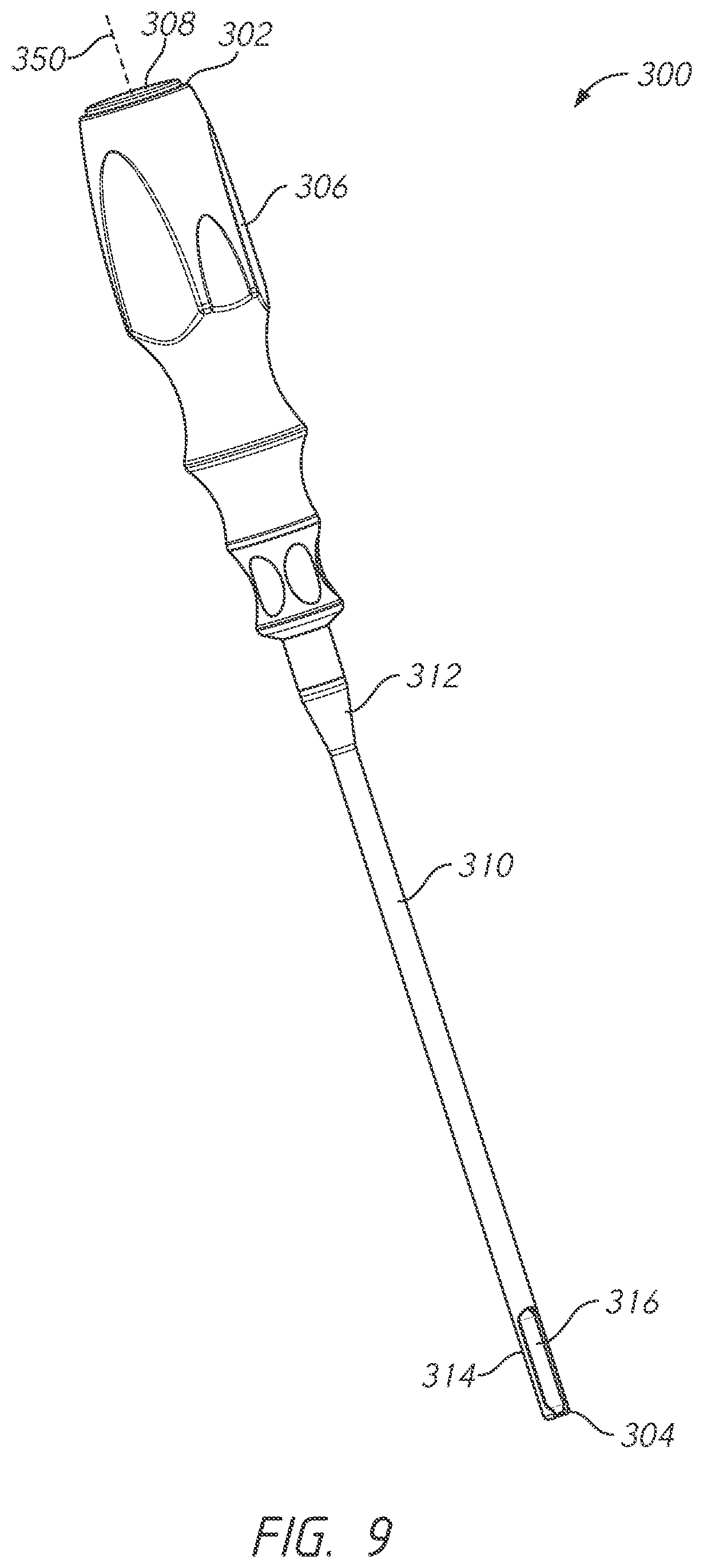
FIG. 9 is a perspective front view of an embodiment of a bone tie retriever.
FIG. 10 is a perspective front view of a distal portion of the bone tie retriever of FIG. 9.
FIG. 11 is a front view of a distal portion of the bone tie retriever of FIG. 9.
FIG. 12 is a cross-sectional view of the distal portion of the bone tie retriever of FIG. 9.
FIG. 13 is a cross-sectional view of the distal portion of the bone tie retriever of FIG. 9.
FIG. 14 is a view of the bone tie of FIG. 1, the bone tie advancer of FIG. 6, and the bone tie retriever of FIG. 9 within the vertebrae.
FIG. 15 is an enlarged view of FIG. 14.
FIG. 16 is a cross-sectional view of the bone tie of FIG. 1 and the bone tie retriever of FIG. 9 within the vertebrae.
FIG. 17 is a side view of the bone tie of FIG. 1, the bone tie advancer of FIG. 6, and the bone tie retriever of FIG. 9.
FIG. 18 is a perspective view of the bone tie of FIG. 1, the bone tie advancer of FIG. 6, and the bone tie retriever of FIG. 9.
FIG. 19 is a perspective view of the bone tie of FIG. 1 and the bone tie retriever of FIG. 9.
FIG. 20 is a perspective view of the bone tie of FIG. 1 and the bone tie retriever of FIG. 9.
FIG. 21 is a distal view of the bone tie of FIG. 1 and the bone tie retriever of FIG. 9.
FIG. 22 is a flow chart for a method of using the bone tie.
FIG. 23 is a view of the bone tie around the transverse processes of adjacent vertebrae.
FIG. 24 is a view of the spine with a coronal plane deformity.
FIG. 25 is a view of the bone tie positioned to correct a coronal plane deformity.
FIG. 26 is a flow chart for a method of using the bone tie.
FIG. 27 is a view of the bone tie around the spinous process of a first vertebra and around the transverse process of a second adjacent vertebra.
FIG. 28 is a view of the spine with a rotational deformity.
FIG. 29 is a view of the bone tie positioned to correct a rotational deformity.
FIG. 30 is a flow chart for a method of using the bone tie.
FIG. 31 is a view of the bone tie around the lamina of adjacent vertebrae.
FIG. 32 is a view of the spine with a sagittal plane deformity.
FIG. 33 is a view of the bone tie positioned to correct a sagittal plane deformity.
FIG. 34 is a flow chart for a method of using the bone tie.
FIG. 35 is a view of the bone tie through the pedicle of a first vertebra and the lamina of a second vertebra.
FIG. 36 is a view of the spine with a lumen being formed through the pedicle of a first vertebra and the lamina of a second vertebra.
FIG. 37 is a view of the bone tie positioned through the lumen.
FIG. 38 is another view of the bone tie positioned through the lumen.
DETAILED DESCRIPTION
Although certain preferred embodiments and examples are disclosed below, it will be understood by those in the art that the disclosure extends beyond the specifically disclosed embodiments and/or uses of the invention and obvious modifications and equivalents thereof. Thus, it is intended that the scope should not be limited by the particular disclosed embodiments described below.
The systems and methods described herein relate to embodiments of bone ties, embodiments of bone tie inserters, and methods of use. The bone tie inserter can facilitate insertion of a bone tie, as described herein. The bone tie can be inserted within a bone lumen, such as a bone lumen between adjacent vertebrae. The bone tie can be advanced by a bone tie advancer. The bone tie can be received by a bone tie retriever. In some embodiments, the bone tie pivots and/or rotates as the bone tie is withdrawn from the bone lumen between adjacent vertebrae.
The methods can include wrapping the bone tie around transverse processes of adjacent vertebrae to correct coronal plane deformity. The methods can include wrapping the bone tie around the spinous process of one vertebra and around the transverse process of a second adjacent vertebra to achieve rotational correction. The methods can include wrapping the bone tie around the lamina of adjacent vertebrae to achieve sagittal correction. The methods can include applying tension to the bone tie to set the sagittal correction. The methods can include passing the bone tie through a lumen in a vertebral body or a pedicle of the inferior vertebra and the lamina or articular process of the superior vertebra.
1. Anatomy of the Spine
The vertebral column comprises a series of alternating vertebrae and fibrous discs that provide axial support and movement to the upper portions of the body. The vertebral column typically comprises thirty-three vertebrae, with seven cervical (C1-C7), twelve thoracic (T1-T12), five lumbar (L1-L5), five fused sacral (S1-S5) and four fused coccygeal vertebrae. Each typical thoracic vertebra includes an anterior body with a posterior arch. The posterior arch comprises two pedicles and two laminae that join posteriorly to form a spinous process. Projecting from each side of the posterior arch is a transverse, superior and inferior articular process. The facets of the superior and inferior articular processes form facet joints with the articular processes of the adjacent vertebrae. The facet joints are true synovial joints with cartilaginous surfaces and a joint capsule.
The orientation of the facet joints vary, depending on the level of the vertebral column. In the C1 and C2 vertebrae, the facet joints are parallel to the transverse plane. In the C3 to C7 vertebrae, the facets are oriented at a 45 degree angle to the transverse plane and parallel to the frontal plane, respectively. This orientation allows the facet joints of the cervical vertebrae to flex, extend, lateral flex and rotate. At a 45 degree angle in the transverse plane, the facet joints of the cervical spine can guide, but do not limit, the movement of the cervical vertebrae. For the thoracic vertebrae, the facets are oriented at a 60 degree angle to the transverse plane and a 20 degree angle to the frontal plane, respectively. This orientation is capable of providing lateral flexion and rotation, but only limited flexion and extension. For the lumbar region, the facet joints are oriented at 90 degree angles to the transverse plane and a 45 degree angle to the frontal plane, respectively. The lumbar vertebrae are capable of flexion, extension and lateral flexion, but little, if any, rotation because of the 90 degree orientation of the facet joints in the transverse plane. The actual range of motion along the vertebral column can vary considerably with each individual vertebra. Vertebrae V1 and V2, as used herein, can refer to any vertebrae within the vertebral column of a patient. In some embodiments, V1 is superior to V2. In some embodiments, V2 is superior to V1. In some embodiments, V1 is adjacent to V2. In some embodiments, V1 and V2 are separated by one or more additional vertebrae.
In addition to guiding movement of the vertebrae, the facet joints also contribute to the load-bearing ability of the vertebral column. One study by King et al. Mechanism of Spinal Injury Due to Caudocephalad Acceleration, Orthop. Clin. North Am., 6:19 1975, found facet joint load-bearing as high as 30% in some positions of the vertebral column. The facet joints may also play a role in resisting shear stresses between the vertebrae. Over time, these forces acting on the facet joints can cause degeneration and arthritis.
2. Bone Tie
FIGS. 1-5 depict views of an embodiment of a bone tie 100. FIG. 1 illustrates a perspective front view. FIG. 2 illustrates a perspective back view. FIG. 3 illustrates a perspective view of a proximal portion of the bone tie 100. FIG. 4 illustrates a perspective view of a distal portion of the bone tie 100. FIG. 5 illustrates an enlarged perspective view of a distal portion of the bone tie 100.
The bone tie 100 can be a generally elongate member. The bone tie 100 can comprise a proximal end 102 and a distal end 104. The bone tie 100 can include a length between the proximal end 102 and the distal end 104. The proximal end 102 can be configured to be near the hands of the user when the user is manipulating the bone tie inserter as described herein. The distal end 104 can be configured to be inserted into a bone lumen as described herein. The distal end 104 can be configured to be the first portion of the bone tie 100 that is inserted in the lumen. The distal end 104 can be the leading end of the bone tie 100. In some methods of use, the proximal end 102 extends away from the vertebrae during insertion of the bone tie 100. In some methods of use, the proximal end 102 is held by the user. In some methods of use, the proximal end 102 is unconstrained during insertion of the bone tie 100. In some methods of use, only a portion of the bone tie 100 near the distal end 104 is grasped and manipulated by the bone tie inserter as described herein. In some methods of use, a portion of the bone tie 100 near the proximal end 102 is retained along the bone tie inserter.
The bone tie 100 can include one or more sections along the length of the bone tie 100. The sections can have a different shape, configuration, or function than an adjacent section of the bone tie 100. In some embodiments, one or more non-adjacent sections can have the same shape, configuration, or function as another section of the bone tie 100. In some embodiments, one or more additional sections are provided. In some embodiments, one or more of the sections provided herein are omitted.
The bone tie 100 can include a fastener section 106. The fastener section 106 can be located at or near the proximal end 102. The fastener section 106 can include any mechanism configured to secure the fastener section 106 to another section of the bone tie 100. The fastener section 106 can include a mechanism that allows the bone tie 100 to be secured in a single direction of travel such as a ratchet. The fastener section 106 can include a mechanism that allows the bone tie 100 to be secured in two directions of travel such as a pair of gears.
The bone tie 100 can include a first section 108. The first section 108 can be closer to the proximal end 102 than the distal end 104. The first section 108 can have a first cross-sectional shape. The first section 108 can extend distally from the fastener section 106. The bone tie 100 can include a second section 110. The second section 110 can be closer to the proximal end 102 than the distal end 104. The second section 110 can have a second cross-sectional shape. The second section 110 can extend distally from the first section 108. The bone tie 100 can include a third section 112. The third section 112 can be closer to the distal end 104 than the proximal end 102. The third section 112 can have a third cross-sectional shape. The third section 112 can extend distally from the second section 110.
The bone tie 100 can include a neck section 114. The neck section 114 can be closer to the distal end 104 than the proximal end 102. The neck section 114 can taper from the third section 112 toward the distal end 104. The neck section 114 can extend distally from the third section 112. The neck section 114 can facilitate manipulation of the distal portion of the bone tie 100 by the bone tie inserter, as described herein. The neck section 114 can be shaped to interface with the bone tie inserter. The neck section 114 can be shaped to form a mechanical interfit or coupling as described herein.
The bone tie 100 can include a head section 116. The head section 116 can be located at or near the distal end 104. The neck section 114 can taper toward the head section 116. The head section 116 can extend distally from the neck section 114. The head section 116 can facilitate manipulation of the distal portion of the bone tie 100 by the bone tie inserter, as described herein. The head section 116 can be shaped to be grasped or cupped by the bone tie inserter. The head section 116 can be shaped to pivot and/or rotate relative to the bone tie inserter.
FIG. 2 is a perspective back view of the bone tie 100. The bone tie 100 can have a smooth surface along the first section 108, the second section 110, and the third section 112. The bone tie 100 can have a continuous surface along the first section 108, the second section 110, and the third section 112.
FIG. 3 illustrates a perspective view of a proximal portion of the bone tie 100. The bone tie can include the proximal end 102, the fastener section 106, first section 108, and the second section 110.
The fastener section 106 can include a lumen 118. The lumen 118 can be oriented perpendicular to a longitudinal axis 150 of the bone tie 100. The bone tie 100 can include a ratchet 122 disposed within the lumen 118. The ratchet 122 is configured to deflect to allow one or gears to travel through the lumen 118 in one direction, but limit or prevent travel in another direction. The fastener section 106 can form an enlarged end of the bone tie 100. The fastener section 106 can be generally rectangular or cuboid. The fastener section 106 can have a width larger than the first section 108. The fastener section 106 can have a thickness larger than the first section 108. The fastener section 106 can include rounded edges or corners. The fastener section 106 can have any shape to accommodate the ratchet 122 disposed therewithin. The fastener section 106 can have any shape to accommodate any fastener mechanism described herein.
The first section 108 can have the first cross-sectional shape. The first cross-sectional shape can be generally rectangular or cuboid. The first cross-sectional shape can have rounded edges or corners. The first section 108 can include a width and a thickness. The first section 108 can include a groove 124. The groove 124 can reduce the thickness of the first section 108. The groove 124 can taper from the fastener section 106. The groove 124 can taper to the second section 110.
The second section 110 can have the second cross-sectional shape. The second cross-sectional shape can be generally rectangular or cuboid. The second cross-sectional shape can have rounded edges or corners. The second section 110 can include a groove 126. The groove 124 of the first section 108 can extend to the groove 126 of the second section 110. The second section 110 can include one or more gears 128. The gears 128 can be ramped surfaces. The gears 128 can form a rack. The gears 128 can be wedge surfaces. The gears 128 can be inclined upward toward the proximal end 102. The gears 128 can be inclined downward toward the distal end 104. The gears 128 can be disposed within the groove 126 of the second section 110. The first section 108 and the second section 110 can include a constant width. The first section 108 and the second section 110 can include a constant thickness. The first section 108 and the second section 110 can include a constant thickness measured along the edges of the first section 108 and the second section 110.
FIG. 4 illustrates a perspective view of a distal portion of the bone tie 100. The bone tie can include the second section 110, the third section 112, the neck section 114, the head section 116, and the distal end 104.
The third section 112 can have a third cross-sectional shape. The third cross-sectional shape can be generally rectangular or cuboid. The third cross-sectional shape can have rounded edges or corners. In some embodiments, the first cross-sectional shape and the third cross-sectional shape are the same or similar. The third section 112 can include a width and a thickness. The third section 112 can include a groove 130. The groove 130 can reduce the thickness of the third section 112. The groove 130 can taper from the second section 110. The groove 130 can taper to the neck section 114.
Two or more of the first section 108, the second section 110, and the third section 112 can include a constant width. Two or more of the first section 108, the second section 110, and the third section 112 can include a constant thickness. Two or more of the first section 108, the second section 110, and the third section 112 can include a constant thickness measured along the edges of the respective sections. The bone tie 100 can have a constant width along a substantial portion of the length. The bone tie 100 can have a constant thickness along a substantial portion of the length.
FIG. 5 illustrates an enlarged view of the distal portion of the bone tie 100. The bone tie 100 can include the neck section 114. The neck section 114 tapers along the width. The neck section 114 tapers from a larger width near the third section 112 to a smaller width near the head section 116. The neck section 114 can include a groove 132. The groove 132 can reduce the thickness of the neck section 114. The groove 132 of the neck section 114 can extend from the groove 130 of the third section 112.
The neck section 114 can lie in a plane along the longitudinal axis 150 of the bone tie 100 or the neck section 114 can include a curve 134. The curve 134 can have a constant radius of curvature. Two or more of the first section 108, the second section 110, and the third section 112 can be planar. The bone tie 100 can lie in a plane along a substantial portion of the length. The curve 134 can extend from the plane of the bone tie. The curve 134 can extend upward from the grooves 124, 126, 130, 132 of the bone tie 100. The curve 134 can extend upward from the gears 128 of the second section 110. The curve 134 can extend away from the longitudinal axis 150 of the bone tie 100.
The bone tie 100 can include the head section 116. The head section 116 can include a head 136. The head 136 can be rounded. The head 136 can be spherical. The head 136 can extend to the distal end 104 of the bone tie 100. The head section 116 can include a flange 138. The flange 138 can be positioned on the head 136. The flange 138 can be a rounded bill that extends from the head 136. The flange 138 can include a first tapered surface 140 and a second tapered surface 142. The first tapered surface 140 and the second tapered surface 142 can have different slopes. The second tapered surface 142 can form a ledge by which the head section 116 or head 136 can be grasped. The first tapered surface 140 and the second tapered surface 142 extend to the neck section 114.
The bone tie 100 can include a marker 144. The marker 144 can facilitate visualization of the bone tie 100, or a portion thereof. In the illustrated embodiment, the head 136 can include the marker 144. The head 136 can include a bore 146. The bore 146 can extend from an edge of the head 136 inward toward or past the center of the head 136. The marker 144 can be disposed within the bore 146. The marker 144 can be a radiopaque marker. The marker 144 can be formed of a metal or other radiopaque material. The marker 144 can identify the distal end 104 of the bone tie 100. In some embodiments, the bone tie 100 comprises a non-radiopaque material. In some embodiments, one or more radiopaque markers may be embedded in or on the bone tie 100 to assist in placement or monitoring of the bone tie 100 under radiographic visualization.
The bone tie 100 can be a flexible fastening band. The bone tie 100 can include the proximal end portion 102 and the distal end portion 104. In some embodiments, the head section 116 can be removed. The neck section 114 can be advanced through the lumen 118. When the neck section 114 is advanced, the ratchet 122 can extend into the groove 132. The third section 112 can be advanced through the lumen 118. When the third section 112 is advanced, the ratchet 122 can extend into the groove 130. The second section 110 can be advanced through the lumen 118. When the second section 110 is advanced, the ratchet 122 can extend into the groove 126. The ratchet 122 can engage the gears 128. The ratchet 122 can allow the second section 110 to travel through the lumen 118 in one direction, but limit travel through the lumen 118 in the opposite direction.
The bone tie 100 can be configured for altering the motion at the facet joints of the vertebral column. In some embodiments, the bone tie 100 can prevent motion of the facet joint. In some embodiments, the bone tie 100 can limit or reduce motion of the facet joint. In some embodiments, the bone tie 100 can limit motion to a range depending on the tightening of the loop of the bone tie 100. In some methods of use, the bone tie promotes fusion of the facet joints.
The bone tie 100 can be configured for altering the spacing at the facet joints of the vertebral column. In some embodiments, the bone tie 100 can reduce the spacing. In some embodiments, the bone tie 100 can maintain the anatomical spacing. The bone tie 100 can be a retaining member for anchoring a prosthesis or implant within the facet joint. In some embodiments, the bone tie 100 can pass through a central opening of the prosthesis or implant when the prosthesis or implant is inserted within the facet joint space. The bone tie 100 can be adapted for securing the location of the prosthesis or implant with respect to at least one of the articular surfaces.
The prosthesis or implant can have any shape or configuration. The prosthesis or implant can be substantially disc shaped. The first side of the prosthesis or implant can be concave, convex, or flat. The second side of the prosthesis or implant can be concave, convex, or flat. The shape can be determined based on a shape of a bone portion that the first side and the second side are configured to contact. In some embodiments, the prosthesis or implant fits entirely within the joint disc space. The prosthesis or implant can include any biocompatible material, e.g., stainless steel, titanium, PEEK, nylon, etc.
The bone tie 100 can have a width of 0.5 mm, 1 mm, 1.5 mm, 2 mm, 2.5 mm, 3 mm, 3.5 mm, 4 mm, or any range of the foregoing values. The width of the bone tie 100 can vary along the length of the bone tie 100. The bone tie 100 can have a thickness of 0.5 mm, 1 mm, 1.5 mm, 2 mm, 2.5 mm, 3 mm, 3.5 mm, 4 mm, or any range of the foregoing values. The thickness of the bone tie 100 can vary along the length of the bone tie 100. The bone tie 100 can have a length of 10 mm, 20 mm, 30 mm, 40 mm, 50 mm, 60 mm, 70 mm, 80 mm, 90 mm, 100 mm, 110 mm, 120 mm, 130 mm, 140 mm, 150 mm, 160 mm, 170 mm, 180 mm, 190 mm, 200 mm, or any range of the foregoing values. For example, the bone tie 100 can have a length of 175 mm. In some embodiments, the second section 110 or the gears 128 can have a length of 5 mm, 10 mm, 15 mm, 20 mm, 25 mm, 30 mm, 35 mm, 40 mm, 45 mm, 50 mm, 60 mm, 65 mm, 70 mm, 75 mm, 80 mm, or any range of the foregoing values.
The bone tie 100 can be manufactured from any of a variety of materials known in the art, including but not limited to a polymer such as polyetheretherketone (PEEK), polyetherketoneketone (PEKK), polyethylene, fluoropolymer, hydrogel, or elastomer; a ceramic such as zirconia, alumina, or silicon nitride; a metal such as titanium, titanium alloy, cobalt chromium or stainless steel; or any combination of the materials described herein. The bone tie 100 can include any biocompatible material, e.g., stainless steel, titanium, PEEK, nylon, etc. In some embodiments, the bone tie 100 comprises at least two materials. The bone tie 100 can include a reinforcement piece disposed within the bone tie 100. By selecting a particular configuration and the one or more materials for the bone tie 100, the bone tie 100 can be designed to have the desired flexibility and resiliency.
In some embodiments, the bone tie 100 can form a unitary structure. The bone tie 100 can be integrally formed from the proximal end 102 to the distal end 104. In some embodiments, the bone tie 100 can include one or more unitarily formed sections along the length of the bone tie 100. One or more of the fastener section 106, the first section 108, the second section 110, the third section 112, the neck section 114, and the head section 116 can be unitarily formed. In some embodiments, the bone tie 100 can include one or more separately formed sections along the length of the bone tie 100. One or more of the fastener section 106, the first section 108, the second section 110, the third section 112, the neck section 114, and the head section 116 can be separately formed. In some embodiments, the marker 144 is separately formed. In some embodiments, the bone tie 100 can form a monolithic structure. The bone tie 100 can be monolithically formed or separately formed. The bone tie 100 can be formed of the same or similar material. The sections of the bone tie 100 can be formed of the same or similar construction. In some embodiments, the bone tie 100 is formed from an injection molding process.
In some embodiments, the shape of the first section 108, the second section 110, and/or the third section 112 can be determined based on the shape of an artificial lumen formed through an articular process of a vertebra. In some embodiments, the shape of the artificial lumen is cylindrical, the shape of the head 136 can be rounded or spherical to allow the head 136 to slideably advance through the artificial lumen. In some embodiments, the shape of the artificial lumen has a cross-sectional dimension or diameter greater than the cross-sectional dimension or diameter of the head 136 to allow the head 136 to slideably advance through the artificial lumen. The head 136 can have a larger cross-sectional dimension or diameter than the first section 108, the second section 110, the third section 112, and the neck section 114 to allow the first section 108, the second section 110, the third section 112, and the neck section 114 to easily slide within the artificial lumen.
In some embodiments, the characteristic of the bone tie 100 can vary along the length of the bone tie 100. The characteristics can vary between one or more of the fastener section 106, the first section 108, the second section 110, the third section 112, the neck section 114, and the head section 116. In some embodiments, each section has different characteristics. In some embodiments, the flexibility of the bone tie 100 varies along the length of the bone tie 100. In some embodiments, the torsional strength of the bone tie 100 varies along the length of the bone tie 100. In some embodiments, the resistance to deformation or elongation of the bone tie 100 varies along the length of the bone tie 100. In some embodiments, the characteristic of the bone tie 100 vary based, at least in part, on the shape of the various sections.
In some embodiments, the characteristic of the bone tie 100 vary based on the material of the various sections. In some embodiments, the characteristic of the bone tie 100 vary along the length based, at least in part, on a reinforcement piece. The reinforcement piece can be separately formed from or integrally formed with the bone tie 100. The reinforcement piece can comprise a different material or material property. In some embodiments, the reinforcement piece is disposed within a section of the bone tie 100. The reinforcement piece can be disposed within the fastener section 106, the first section 108, the second section 110, the third section 112, the neck section 114, the head section 116, any combination of the foregoing, or disposed only within one or more sections of the foregoing. The reinforcement piece can increase the strength of a section of the bone tie 100. In some embodiments, the reinforcement piece has a substantially uniform shape. The shape, material, or other characteristics of the reinforcement piece can be selected depending on the desired bending and/or torsion characteristics of the material chosen. The reinforcement piece can increase or decrease bending strength. The reinforcement piece can increase or decrease torsion strength. Any shape, material, or other property of the reinforcement piece can be selected to achieve the desired bending and/or torsion strength of the bone tie 100. In some embodiments, the reinforcement piece is radiopaque. In some embodiments, the reinforcement piece is radiolucent.
3. Bone Tie Advancer
FIGS. 6-8 depict views of an embodiment of a bone tie advancer 200. FIG. 6 illustrates a perspective front view. FIG. 7 illustrates a perspective front view of a distal portion. FIG. 8 illustrates a perspective back view of a distal portion. The bone tie advancer 200 can include a proximal end 202 and a distal end 204.
The bone tie advancer 200 can include a proximal handle 206. The proximal handle 206 can be any shape configured to be gripped by the user. The proximal handle 206 can include one or more grooves designed to accommodate the fingers of the user. The proximal handle 206 can be shaped for right-handed use, left-handed use, or ambidextrous use. The proximal handle 206 can include an impact cap 208. The impact cap 208 can have a flat proximal end to allow a force to be applied.
The bone tie advancer 200 can include a shaft 210. The shaft 210 can extend distally from the proximal handle 206. The shaft 210 can include an upper portion 212. The upper portion 212 can be cylindrical. The upper portion 212 can have one or more cylindrical sections of varying diameters. The upper portion 212 can include a stepped surface. The upper portion 212 can have any cross-sectional shape including round, square, rectangular, polygonal, oval, or any other shape. The upper portion 212 can be an elongate member. The upper portion 212 can lie along a longitudinal axis 250.
The shaft 210 can include a tapered portion 214. The tapered portion 214 can be distal to the upper portion 212 of the shaft 210. The tapered portion 214 can have a narrower cross-section toward the distal end 204. The tapered portion 214 can be frusto-conical. The tapered portion 214 can have a reduced cross-section relative to the upper portion 212 of the shaft 210 to enable the shaft 210 to be positioned relative to the patient's anatomy. The tapered portion 214 can lie along the longitudinal axis 250. The tapered portion 214 can taper inward relative to the longitudinal axis 250. The upper portion 212 and the tapered portion 214 can be coaxial.
The shaft 210 can include a curved portion 216. The curved portion 216 can be distal to the tapered portion 214 of the shaft 210. The curved portion 216 can have a substantially constant width. The curved portion 216 can have a reduced cross-section relative to the upper portion 212 of the shaft 210 to enable the shaft 210 to be positioned relative to the patient's anatomy. The curved portion 216 can be shaped to be inserted within the artificial lumen of the bone portions. The curved portion 216 can be shaped according to the lumen-forming tool that creates the lumen in the bone portions. The curved portion 216 can have a constant radius of curvature. The curved portion 216 can curve away from the longitudinal axis 250 of the upper portion 212. The curved portion 216 can extend laterally from the longitudinal axis 250 of the upper portion 212.
FIGS. 7 and 8 are enlarged views of the distal portion of the bone tie advancer 200. The curved portion 216 can include a rounded surface 218. The rounded surface 218 can extend distally from the tapered portion 214. The rounded surface 218 can be proximal-facing. The shaft 210 can include a planar surface 220. The planar surface 220 can be distal-facing. The planar surface 220 can form the outside curve of the curved portion 216. The rounded surface 218 can form the inside curve of the curved portion 216. The planar surface 220 can extend along at least a portion of the curved portion 216. The planar surface 220 can extend along at least a portion of the tapered portion 214.
The shaft 210 can include an advancer portion 222. The advancer portion 222 can be configured to interface with the bone tie 100. The advancer portion 222 can be located at or near the distal end 204 of the bone tie advancer 200. The advancer portion 222 can include a curved surface 224. The curved surface 224 can correspond to the curvature of the head 136. The curved surface 224 can cup the head 136. The curved surface 224 can curve around the distal-facing portion of the head 136. The curved surface 224 can allow the force of the bone tie advancer 200 to be transferred to the head 136. The curved surface 224 can allow movement of the bone tie advancer 200 to be transferred to the head 136. The curved surface 224 can form the distal end 204 of the bone tie advancer 200. The advancer portion 222 can include a tapered surface 226. The tapered surface 226 can be proximal-facing. The tapered surface 226 can allow visualization and clearance relative to the patient's anatomy. The advancer portion 222 can include retaining arms 230. The retaining arms 230 can extend proximally from the curved surface 224 and can be separately formed from or integrally formed with the curved surface 224. The retaining arms 230 can engage the flange 138. The retaining arms 230 can engage the second tapered surface 142 of the flange 138. The retaining arms 230 can engage the neck section 114. The interior portion of the retaining arms 230 can be rounded, tapered, or any other shape corresponding to the flange 138, second tapered surface 142 and/or neck section 114. The retaining arms 230 can facilitate secure engagement of the bone tie 100 for insertion of the bone tie 100 within the artificial lumen of the bone portions.
The advancer portion 222 can include a channel 228. The channel 228 can correspond to the shape of the neck section 114 of the bone tie 100. The neck section 114 of the bone tie 100 can be disposed within the channel 228 when the curved surface 224 abuts the head 136. The channel 228 can be formed by three sides. The three sides can include rounded edges. The three sides can have any shape to accept the bone tie 100. The channel 228 can include an open side. The open side can be distal-facing. The channel 228 can surround a portion of the neck section 114 of the bone tie 100. When the neck section 114 of the bone tie 100 is disposed within the channel 228, the curved surface 224 can align and abut the head 136. The channel 228 can increase the contact between the advancer portion 222 and the bone tie 100.
4. Bone Tie Retriever
FIGS. 9-13 depict views of an embodiment of a bone tie retriever 300. FIG. 9 illustrates a perspective front view. FIG. 10 illustrates a perspective front view of a distal portion. FIG. 11 illustrates a front view of a distal portion. FIG. 12 illustrates a cross-sectional view of the distal portion. FIG. 13 illustrates a cross-sectional view of the distal portion. The bone tie retriever 300 can include a proximal end 302 and a distal end 304.
The bone tie retriever 300 can include a proximal handle 306. The proximal handle 306 can be any shape configured to be gripped by the user. The proximal handle 306 can include one or more grooves designed to accommodate the fingers of the user. The proximal handle 306 can be shaped for right-handed use, left-handed use, or ambidextrous use. The proximal handle 306 can include an impact cap 308. The impact cap 308 can have a flat proximal end to allow a force to be applied. The proximal handles 206, 306 can be the same or similar. The proximal handles 206, 306 can be mirror images. In some embodiments, the proximal handle 206 can be designed for use with the right hand of the user and the proximal handle 306 can be designed for use with the left hand of the user. The proximal handles 206, 306 can be different. The proximal handles 206, 306 can include a different visual indicator to indicate the different functions of the bone tie advancer 200 and the bone tie retriever 300. In some embodiments, the proximal handles 206, 306 can be different colors or include a visual marking.
The bone tie retriever 300 can include a shaft 310. The shaft 310 can extend distally from the proximal handle 306. The shaft 310 can include an upper portion 312. The upper portion 312 can be cylindrical. The upper portion 312 can have one or more cylindrical sections of varying diameters. The upper portion 312 can include a stepped surface. The upper portion 312 can have any cross-sectional shape including round, square, rectangular, polygonal, oval, or any other shape. The upper portion 312 can be an elongate member. The upper portion 312 can lie along a longitudinal axis 350. The upper portions 212, 312 can be the same or substantially similar. The shaft 310 can include a retriever portion 314. The retriever portion 314 can be distal to the upper portion 312 of the shaft 310.
FIG. 10 illustrates an enlarged view of a distal portion of the bone tie retriever 300. The retriever portion 314 can be shaped to receive the head 136 of the bone tie 100. The retriever portion 314 can include a channel 316. The channel 316 can include a rounded portion 320. The rounded portion 320 can include a curvature corresponding to the head 136 of the bone tie 100. The channel 316 can be concave along the longitudinal axis 350.
The channel 316 can include a ledge 318. The ledge 318 can be flat, curved, or tapered. The ledge 318 can include a curvature that corresponds to the curvature of the head 136. The ledge 318 can be dimensioned to allow for pivotal and/or rotational movement of the head 136 within the channel 316. In some embodiments, the ledge 318 can have a curved or poly-axial surface configured to accept the head 136. In some embodiments, the ledge 318 can be concave. In some embodiments, the ledge 318 can have a concavity that corresponds to a convexity of the head 136. The concavity of the ledge 318 can allow the head 136 to pivot and/or rotate while still retaining the head 136 within the channel 316. The ledge 318 can allow the head 136, and thus the bone tie 100, to pivot 10.degree., 20.degree., 30.degree., 40.degree., 50.degree., 60.degree., 70.degree., 80.degree., 90.degree., 100.degree., 110.degree., 120.degree., 130.degree., 140.degree., 150.degree., 160.degree., 170.degree., 180.degree., or any range of the foregoing values. In particular embodiments, the ledge 318 can allow the head 136, and thus the bone tie 100, to pivot 60.degree., 70.degree., 80.degree., 90.degree., or any range of the foregoing values. The ledge 318 can allow the head 136 to abut and rotate against the ledge 318.
The retriever portion 314 can include an opening 322. The opening 322 can be located at or near the distal end 304. The ledge 318 surrounds the opening 322. The ledge 318 can be shaped to allow the neck section 114 to pass through the opening 322. The ledge 318 can be shaped to prevent the head 136 from passing through the opening 322. The ledge 318 can be sized according to the corresponding bone tie 100.
The retriever portion 314 can include one or more retention features 324. In the illustrated embodiment, the retriever portion 314 includes two retention features 324. The one or more retention features 324 narrow the channel 316 near the distal end 304. The channel 316 extends through the one or more retention features 324. The one or more retention features 324 can be disposed near the ledge 318. The one or more retention features 324 can function to retain the head 136 when the head 136 is seated against the ledge 318.
In some embodiments, the channel 316 may be dimensioned to allow entry of the head 136, or the head 136 and neck section 114, in generally one particular orientation. In some embodiments, the channel 316 may be dimensioned to allow entry of the head 136, or the head 136 and neck section 114, in a range of orientations. In some embodiments, the channel 316 may be dimensioned to allow entry of the head 136 wherein the neck section 114 is generally perpendicular to the longitudinal axis 350 of the shaft 310. In some embodiments, the channel 316 may be dimensioned to allow retention of the head 136 wherein the neck section 114 is generally parallel to or coaxial with the longitudinal axis 350. In some embodiments, the channel 316 is configured to allow the neck section 114 to pass between the one or more retention features 324. In some embodiments, the retriever portion 314 is configured to allow the neck section 114 to pivot, or pivot and rotate, from extending between the one or more retention features 324 to extending into the opening 322. In some embodiments, the retriever portion 314 is configured to allow the neck section 114 to pivot, or pivot and rotate, from the opening 322 to the channel 316. In some embodiments, the channel 316 is configured to prevent or limit the head 136 from passing between the one or more retention features 324.
5. Methods of Use
FIGS. 14 and 15 illustrate the bone tie 100, the bone tie advancer 200, and the bone tie retriever 300 in relation to vertebrae during methods of use. FIGS. 14 and 15 illustrate the bone tie 100, the bone tie advancer 200, and the bone tie retriever 300. The proximal ends are visible and the distal ends are disposed within lumens in the vertebrae. FIG. 15 is a close-up view of FIG. 14. FIG. 16 is a cross-sectional view illustrating a placement of the bone tie 100 and the bone tie retriever 300 in relation to the vertebrae.
The bone tie 100 can be configured to stabilize or fuse adjacent vertebrae. The bone tie 100 can be used to fuse a vertebra V1 and vertebra V2 via the inferior articular process IAP1A of vertebra V1 and the superior articular process SAP2A of vertebra V2. In some methods of use, a second bone tie 100 can be used to fuse a vertebra V1 and vertebra V2 via the inferior articular process IAP1B of vertebra V1 and the superior articular process SAP2B of vertebra V2. In some embodiments, vertebra V1 and vertebra V2 are fused using only one of bone tie 100. In some embodiments, one bone tie 100 can be used to stabilize vertebra V1 and vertebra V2 via one of the inferior articular process IAP1A of vertebra V1 and the superior articular process SAP2A of vertebra V2, or, via the inferior articular process IAP1B of vertebra V1 and the superior articular process SAP2B of vertebra V2. In some embodiments, two bone ties 100 can be used to stabilize vertebra V1 and vertebra V2 via both of the inferior articular process TAPIA of vertebra V1 and the superior articular process SAP2A of vertebra V2, and, the inferior articular process IAP1B of vertebra V1 and the superior articular process SAP2B of vertebra V2. The methods described herein can be repeated for any pair of an inferior articular process and a superior articular process.
In some methods of use, a lumen is formed through the articular processes. The lumen can be formed with a lumen-forming tool, such as a drill, tissue punch, or reamer. The lumen is formed through one or more articular processes of the vertebrae to facilitate implantation of the bone tie 100. In some embodiments, at least a portion of the lumen has a curved or non-linear configuration. In some embodiments, at least a portion of the lumen has a straight or linear configuration. In some methods of use, two or more lumens are formed. A drill or other device can be used to form a lumen in superior articular process SAP of vertebra V2 and inferior articular process IAP of vertebra V1. Specifically, the drill can be used to form the lumen in a facet of superior articular process SAP of vertebra V2 and to form the lumen in a facet of inferior articular process IAP of vertebra V1. In some embodiments, one lumen-forming tool forms one or more lumens. In some embodiments, two lumen-forming tools are utilized to form two lumens.
In some methods of use, a portion of the surface of the facet of SAP and IAP can be prepared for fusion. In some methods of use, a portion of the surface of the facet can be ground, scored, roughened, or sanded, such that the surface of the facet can better adhere to any substances to aid in fusion and/or otherwise fuse more readily to an implant or prosthesis. In some methods of use, the surgical procedure can include preparing the area near and/or around the vertebra by, for example, removing all or a portion of ligaments, cartilage, and/or other tissue. In some methods of use, the area near and/or around a facet joint can be prepared by removing all or a portion of the facet joint capsule. The implant or prosthesis, if provided, can be inserted between the superior articular process SAP of vertebra V2 and inferior articular process IAP of vertebra V1.
FIG. 16 illustrates a cross-sectional view of the vertebrae. The bone tie 100, the bone tie advancer 200 (not shown in FIG. 16), and the bone tie retriever 300 can be located within lumens as described herein. The first lumen 400 can be curved. The first lumen 400 can extend from a first vertebra toward a second vertebra. The first lumen 400 can extend through the facet joint space. The second lumen 402 can be straight. The second lumen 402 can extend downward from a surface of the second vertebra. The second lumen 402 can extend only through the second vertebra. The second lumen 402 can intersect the first lumen 400.
The bone tie 100 can be positioned within and adjacent to the bone tie advancer 200. As the bone tie advancer 200 is moved by the user, the head section 116 and the neck section 114 is correspondingly moved. The bone tie 100 can be advanced through the first lumen 400 by the bone tie advancer 200. The bone tie 100 can be advanced through the facet joint space by the bone tie advancer 200. The bone tie 100 can be advanced through at least a portion of the second lumen 402 by the bone tie advancer 200. In some embodiments, the bone tie 100 and the bone tie advancer 200 can have a bend or curve to facilitate directing the head 136 of the bone tie 100 into the lumen 400. In some embodiments, the bone tie 100 and the bone tie advancer 200 can have a bend or curve corresponding to the curvature of the first lumen 400. The bone tie 100 and the bone tie advancer 200 can have any shape that allows the passage through the first lumen 400 and into the second lumen 402.
The bone tie 100 is advanced until the head 136 of bone tie 100 is positioned near the bone tie retriever 300. The bone tie 100 is advanced until the head 136 of bone tie 100 is inserted into the channel 316. The bone tie 100 and the bone tie advancer 200 can have any shape that allows the passage of the head 136 into the channel 316. The bone tie 100 can be advanced until the head 136 abuts the inside wall of the retriever portion 314. The bone tie 100 can be advanced until any further advancement is prevented by the retriever portion 314.
During advancement, the head 136 of the bone tie 100 can be monitored under radiographic visualization. The head 136 can include one or more markers 144. In the illustrated embodiment, the head 136 can include a bore 146 configured to receive the marker 144. The marker 144 can facilitate visualization of the head 136 because the marker 144 can be radiopaque. The marker 144 can facilitate placement of the head 136 relative to the lumens 400, 402. The marker 144 can facilitate placement of the head 136 relative to the retriever portion 314.
FIGS. 17-18 illustrate the bone tie 100, the bone tie advancer 200, and the bone tie retriever 300 during methods of use. FIG. 17 is a side view of the bone tie 100, the bone tie advancer 200, and the bone tie retriever 300. FIG. 18 is a perspective view of the bone tie 100, the bone tie advancer 200, and the bone tie retriever 300.
The bone tie 100 can be coupled to the bone tie advancer 200. FIG. 17 illustrates the bone tie 100 coupled to the bone tie advancer 200. FIG. 18 is an enlarged view of the distal portion. The bone tie 100 can include the neck section 114 and the head section 116. The bone tie advancer 200 can include the advancer portion 222. The advancer portion 222 can couple to the head section 116 of the bone tie 100. The advancer portion 222 can couple to the head 136 of the bone tie 100. The advancer portion 222 can include a curved surface 224 that can grasp the head 136. The advancer portion 222 can couple to the neck section 114 of the bone tie 100. The advancer portion 222 can include a channel 228 that can grasp a portion of the neck section 114. The advancer portion 222 can couple to the bone tie 100 prior to insertion of the bone tie 100, or after bone tie 100 has been inserted, into a lumen in a bone portion. The movement of the bone tie advancer 200 can cause movement of the bone tie 100.
The bone tie advancer 200 can move the head 136 of the bone tie 100 toward the bone tie retriever 300. The retriever portion 314 can include the channel 316. The channel 316 can be concave along the longitudinal axis 350 of the shaft 310. The channel 316 can be shaped to receive the head 136 of the bone tie 100. The head 136 can be inserted proximal to the one or more retention features 324. The head 136 can be inserted along the length of the channel 316. The head 136 can be inserted proximal to the ledge 318. The head 136 can be inserted proximal to the opening 322.
The head 136 enters the channel 316 when advanced by the bone tie advancer 200. The neck section 114 enters the channel 316 when advanced by the bone tie advancer 200. In some methods of use, the bone tie advancer 200 enters the channel 316. In some methods of use, the bone tie advancer 200 does not enter the channel 316.
The bone tie advancer 200 can be used to advance the bone tie 100 through the first lumen 400. The first lumen 400 can be curved. The bone tie advancer 200 can include the curved portion 216. The curved portion 216 can have the same or similar curvatures as the curved lumen 400. The curved lumen 400 can be formed in the bone to allow passage of the bone tie advancer 200. The user manipulates the proximal handle 206 to align the advancer portion 222 with the opening of the first lumen 400. The user can pivot and/or rotate and translate the bone tie advancer 200 to move the bone tie advancer 200 and the bone tie 100 through the first vertebra V1. The user can pivot and/or rotate and translate the bone tie advancer 200 to move the bone tie advancer 200 and the bone tie 100 through the facet joint space. The user can pivot and/or rotate and translate the bone tie advancer 200 to move the bone tie advancer 200 and the bone tie 100 into the second vertebra V2.
The bone tie retriever 300 can be inserted into the second lumen 402. The second lumen 402 can be generally straight. The second lumen 402 can extend distally beyond the first lumen 400. The second lumen 402 can extend to a depth to allow the channel 316 of the bone tie retriever 300 to align with the first lumen 400 when the bone tie retriever 300 is within the second lumen 402. The second lumen 402 can be any size or depth in order to accommodate the retriever portion 314 therewithin. The retriever portion 314 can be positioned within the second lumen 402 such that when the head section 116 is advanced from the first lumen 400, the head section 116 is inserted along the length of the channel 316. In some embodiments, the retriever portion 314 can be positioned within the second lumen 402 such that when the head section 116 is advanced from the first lumen 400, the head section 116, or the head section 116 and at least a portion of the neck section 114, is inserted along the length of the channel 316. The retriever portion 314 can be positioned such that the head 136 is inserted proximal to the one or more retention features 324. In some embodiments, the distal end 304 of the bone tie retriever 300 can be recessed below the first lumen 400 when the bone tie retriever 300 is received within the second lumen 402.
FIGS. 19-21 illustrate the bone tie 100 and the bone tie retriever 300 during methods of use. FIG. 19 is a perspective view of the bone tie 100 and the bone tie retriever 300 in a first orientation. FIG. 20 is a perspective view of the bone tie 100 and the bone tie retriever 300 in a second orientation. FIG. 21 is a distal view of the bone tie 100 and the bone tie retriever 300 in the second orientation.
FIG. 19 is a perspective view of the bone tie 100 and the bone tie retriever 300 in a first orientation. In some methods of use, the head 136 of the bone tie 100 is inserted into the bone tie retriever 300 in generally one particular orientation. In some methods of use, the neck section 114 of the bone tie 100 is perpendicular to the longitudinal axis 350 of the bone tie retriever 300 when the bone tie 100 is inserted into the bone tie retriever 300. In some methods of use, the head 136 of the bone tie 100 is inserted into the bone tie retriever 300 in a range of orientations. In some methods of use, the neck section 114 of the bone tie 100 is generally skewed to the longitudinal axis 350 of the bone tie retriever 300 when the bone tie 100 is inserted into the bone tie retriever 300. In some methods of use, the neck section 114 of the bone tie 100 can be any angle to the longitudinal axis 350 of the bone tie retriever 300 including 10.degree., 20.degree., 30.degree., 40.degree., 50.degree., 60.degree., 70.degree., 80.degree., 90.degree., 100.degree., 110.degree., 120.degree., 130.degree., 140.degree., 150.degree., 160.degree., 170.degree., 180.degree., or any range of the foregoing values. In particular methods of use, the neck section 114 of the bone tie 100 can be any angle to the longitudinal axis 350 of the bone tie retriever 300 including 60.degree., 70.degree., 80.degree., 90.degree., 100.degree., 110.degree., 120.degree., or any range of the foregoing values.
FIG. 20 is a perspective view of the bone tie 100 and the bone tie retriever 300 in a second orientation. FIG. 21 is a distal view of the bone tie 100 and the bone tie retriever 300 in the second orientation. In some methods of use, the neck section 114 of the bone tie 100 is generally aligned with the longitudinal axis 350 of the bone tie retriever 300 when the bone tie 100 is pivoted. In some methods of use, the neck section 114 of the bone tie 100 can be any angle to the longitudinal axis 350 of the bone tie retriever 300 including 0.degree., 5.degree., 10.degree., 15.degree., 20.degree., 25.degree., 30.degree., 35.degree., 40.degree., 45.degree., 50.degree., 55.degree., 60.degree., or any range of the foregoing values.
In some methods of use, the head 136 of the bone tie 100 is configured to slide within the channel 316. In some methods of use, the head 136 slides distally within the channel 316. The channel 316 can include the ledge 318. The ledge 318 can include a curvature that corresponds to the curvature of the head 136. The ledge 318 can be dimensioned to allow for pivotal and/or rotational movement of the head 136 within the channel 316. In some embodiments, the ledge 318 can have a curved or poly-axial surface configured to accept the head 136. In some embodiments, the ledge 318 can be concave. In some embodiments, the ledge 318 can have a concavity that corresponds to a convexity of the head 136. The ledge 318 can allow the head 136 to abut and rotate against the ledge 318. The one or more retention features 324 can allow the head 136 to be seated and rotate within the distal portion of the bone tie retriever 300. As the head 136 slides distally, the neck section 114 slides between the one or more retention features 324.
The concavity of the ledge 318 can allow the head 136 to pivot and/or rotate while still retaining the head 136 within the channel 316. The ledge 318 can allow the head 136, and thus the bone tie 100, to pivot and/or rotate. In some methods of use, the bone tie 100 can pivot approximately 90.degree.. In some methods of use, the bone tie 100 pivots 30.degree., 40.degree., 50.degree., 60.degree., 70.degree., 80.degree., 90.degree., 100.degree., 110.degree., 120.degree., 130.degree., 140.degree., 150.degree., or any range of the foregoing values.
In some embodiments, the channel 316 may be dimensioned to allow retention of the head 136 when the neck section 114 is generally parallel or coaxial to the longitudinal axis 350 of the shaft 310. In some embodiments, the channel 316 is configured to allow the neck section 114 to pass between the one or more retention features 324. In some embodiments, the retriever portion 314 is configured to allow the neck section 114 to pivot, or pivot and rotate, from extending between the one or more retention features 324 into the opening 322. The opening 322 can be located at or near the distal end 304. The ledge 318 surrounds the opening 322. The ledge 318 can be shaped to support the head 136 when the bone tie 100 is pivoted and/or rotated. The ledge 318 and/or the one or more retention features 324 can be shaped to constrain the head 136 when the bone tie 100 is pivoted and/or rotated.
The bone tie 100 can be retracted by the bone tie retriever 300. The bone tie retriever 300 can be pulled distally from the second lumen 402. The neck section 114 can pivot and/or rotate to extend distally from the bone tie retriever 300 as the bone tie 100 is pulled proximally. The one or more retention features 324 can limit or prevent lateral movement of the head 136 when the bone tie is in the second orientation relative to the bone tie retriever 300. The one or more retention features 324 can facilitate retention of the head 136 within the channel 316. The bone tie retriever 300 can pull the bone tie 100 through the second lumen 402. The bone tie retriever 300 can pull the bone tie 100 until the distal end 104 of the bone tie 100 is outside of the lumen 402.
In some methods of use, the proximal end 102 and the distal end 104 can be outside of the vertebrae after use of the bone tie advancer 200 and bone tie retriever 300. The bone tie 100 can form a curved shape. In some methods of use, a portion of the second section 110 can be disposed within the lumens 400, 402. In some methods of use, a portion of the third section 112 can be disposed within the lumens 400, 402. In some methods of use, a portion of the second section 110 and a portion of the third section 112 can be disposed within the lumens 400, 402 when the proximal end 102 and the distal end 104 are outside of the vertebrae.
In some methods of use, the head section 116 can be removed. The bone tie 100 can be cut or severed near the neck section 114. The bone tie 100 can be cut or severed to remove the head section 116. The bone tie 100 can be cut or severed to remove the head section 116 and a portion of the neck section 114. The head section 116 can be discarded. The head section 116 and a portion of the neck section 114 can be discarded. The neck section 114 can be advanced through the lumen 118 of the fastener section 106. While the neck 114 is being advanced, the ratchet 122 can extend into the groove 132. The third section 112 can be advanced through the lumen 118. While the third section 112 is being advanced, the ratchet 122 can extend into the groove 130. The second section 110 can be advanced through the lumen 118. While the second section 110 is being advanced, the ratchet 122 can extend into the groove 126. The ratchet 122 can engage the one or more gears 128. The ratchet 122 can allow the second section 110 to travel through the lumen 118 in one direction, but limit or prevent travel in the opposite direction.
The bone tie 100 can form a loop. The fastener section 106 can be secured to the second section 110. Securing the fastener section 106 can be based on the type of fastener member used. By way of example, securing the fastener section 106 can include inserting the opposite end of the bone tie 100 into the lumen 118 of the fastener section 106, and advancing the opposite end through the fastener section 106. The fastener section 106 can engage the one or more gears 128 of the second section 110. The one or more gears 128 can be shaped to allow each gear 128 to displace the ratchet 122 of fastener section 106 in only one direction.
After the bone tie 100 is secured, superior articular process SAP of vertebra V2 can fuse to inferior articular process IAP of vertebra V1. Fusing can include one or more of bone material from superior articular process SAP of vertebra V2, bone material from inferior articular process IAP of vertebra V1, and/or the implant or prosthesis that fuses superior articular process SAP of vertebra V2 to inferior articular process IAP of vertebra V1. In some embodiments, after superior articular process SAP of vertebra V2 is fused to inferior articular process IAP of vertebra V1, the bone tie 100 is not removed. In some embodiments, after superior articular process SAP of vertebra V2 is fused to inferior articular process IAP of vertebra V1, all or a portion of the bone tie 100 can be removed. In some embodiments, the bone tie 100 can be removed after fusion of superior articular process SAP of vertebra V2 to inferior articular process IAP of vertebra V1 has started, but has not finished. In some embodiments, the bone tie 100 may comprise a bioabsorbable or bioresorbable material.
In use, the bone tie 100 can be configured to stabilize a first vertebra and/or a second vertebra by securing an articular process of the first vertebra to an articular process of a second vertebra. More specifically, the bone tie 100 can be configured to stabilize the first vertebra and/or a second vertebra by securing an articular process of the first vertebra to an articular process of a second vertebra. The bone tie 100 can be placed into a suitable position relative to the first vertebra and/or the second vertebra, and a distal portion of the bone tie 100 can be inserted into the lumen of the fastener section 106. The bone tie 100 can be configured to substantially encircle at least a portion of the first vertebra and the second vertebra. In some methods of use, the bone tie 100 forms a loop about the articular process of the first vertebra and the articular process of the second vertebra. In some methods of use, the neck section 114 and the third section 112 can be advanced through the fastener section 106 such that the area disposed within the loop formed by the bone tie 100 is reduced.
As the bone tie 100 is tightened, the bone tie 100 exerts a compressive force on the articular process of the first vertebra and the articular process of the second vertebra. In some methods of use, the implant or prosthesis can be disposed between the articular process of the first vertebra and the articular process of the second process such that a desired distance between the articular process of the first vertebra and the articular process of the second process is maintained. The implant or prosthesis can be retained within a loop or other defined segment of the bone tie 100. In some methods of use, the excess portion of the second section 110 and/or the third section 112 can be removed once the bone tie 100 is tightened. In some embodiments, the excess portion of the bone tie 100 can be removed from the space around the vertebrae. The excess portion of the bone tie 100 can be removed by cutting or breaking the excess portion of the bone tie 100. The excess portion can be removed without loosening or removing the loop formed by the bone tie 100 around the first vertebra and the second vertebra.
FIG. 22 is a flow chart for a method of using the bone tie 100. FIG. 23 illustrates a view of the vertebrae. FIG. 24 is a view of the spine with a coronal plane deformity. FIG. 25 is a view of the bone tie 100 positioned to correct a coronal plane deformity. The bone tie 100 can be positioned around the transverse processes of adjacent vertebrae. The bone tie 100 can be positioned via the bone tie advancer 200. The bone tie 100 can be captured by the bone tie retriever 300. In some embodiments, the surgeon can position the bone tie 100 without the bone tie advancer 200. In some embodiments, the surgeon can capture the bone tie 100 without the bone tie retriever 300. In some embodiments, the surgeon can position the bone tie manually, depending on the anatomical location of fixation and the patient's anatomy. Manual positioning can be by hand and/or by use of one or more of various tools.
The bone tie 100 can be configured to correct a deformity of adjacent vertebrae. The bone tie 100 can be configured to provide a torque or rotational force. The bone tie 100 can be configured to stabilize the vertebrae in a corrected position. The bone tie 100 can be configured to fuse the vertebrae in a corrected position. The bone tie 100 can be anchored to one or more specific anatomical locations to provide the appropriate torque. The bone tie 100 can include one or more fastener portions to anchor the bone tie 100 to the spinous process and/or the transverse process with one or more fasteners. The bone tie 100 can include one or more fastener portions to anchor the bone tie 100 to any anatomical portion of vertebra V1 and/or any anatomical portion of vertebra V2 with one or more fasteners.
The bone tie 100 can be used to fuse the vertebra V1 and vertebra V2 via the transverse process TP1A of vertebra V1 and the transverse process TP2A of vertebra V2. In some methods of use, a second bone tie 100 can be used to fuse the vertebra V1 and vertebra V2 via the transverse process TP1B of vertebra V1 and the transverse process TP2B of vertebra V2. In some embodiments, the rotational alignment of vertebra V1 and vertebra V2 is corrected using only one bone tie 100. In some embodiments, one bone tie 100 can be used to correct vertebra V1 and vertebra V2 via the right transverse process TP1A of vertebra V1 and the right transverse process TP2A of vertebra V2, or, via the left transverse process TP1B of vertebra V1 and the left transverse process TP2B of vertebra V2. For an example reference herein, the transverse processes TP1A, TP2A are on the right when viewed from the front of the patient and the transverse processes TP1B, TP2B are on the left when viewed from the front of the patient. In some embodiments, two bone ties 100 can be used to stabilize vertebra V1 and vertebra V2. In some embodiments that utilize two bone ties 100, one bone tie 100 is positioned around the transverse process TP1A of vertebra V1 and the transverse process TP2A of vertebra V2 (shown in FIG. 23) and another bone tie is positioned around the transverse process TP1B of vertebra V1 and the transverse process TP2B of vertebra V2 (not shown). In some embodiments that utilize two bone ties 100, two bone ties 100 are positioned around the transverse process TP1A of vertebra V1 and the transverse process TP2A of vertebra V2. Other configurations are contemplated. In some embodiments, the two bone ties 100 exert the same rotational force. In some embodiments, the two bone ties 100 exert a different rotational force. The methods described herein can be repeated for any pair of transverse processes.
In some methods of use, a pathway is formed around the transverse processes. The pathway can be formed with any tool, such as a dilator or retractor. The pathway can be formed via a posterior approach to the spine. The pathway can be formed via a lateral approach to the spine. The pathway can be formed via minimally invasive surgical techniques. The pathway can be formed via any of a variety of approaches to the spine. The pathway is formed around two or more transverse processes of vertebrae to facilitate implantation of the bone tie 100. In some embodiments, at least a portion of the pathway has a curved or non-linear configuration. In some embodiments, at least a portion of the pathway has a straight or linear configuration. In some methods of use, two or more pathways are formed. In some embodiments, one tool forms one or more pathways. In some embodiments, two tools are utilized to form two pathways.
In some methods of use, a portion of the surface of the transverse process can be prepared for receiving bone tie 100. In some methods of use, a portion of the surface of the transverse process can be ground, scored, roughened, or sanded, such that the surface of the transverse process can better receive the bone tie 100. In some methods of use, the surgical procedure can include preparing the area near and/or around the transverse processes by, for example, removing all or a portion of ligaments, cartilage, and/or other tissue.
In some methods, the facet joint is prepared prior to securing the bone tie 100 around the transverse processes. In some methods of use, the area near and/or around a facet joint can be prepared by removing all or a portion of the facet joint capsule. The implant or prosthesis, if provided, can be inserted between the superior articular process SAP of vertebra V2 and inferior articular process IAP of vertebra V1.
In some methods of use, a portion of the vertebra can be prepared for fusion. In some methods of use, an intervertebral implant is inserted between the superior and inferior vertebrae. The intervertebral implant can be a cage configured to be packed with material to promote fusion. The intervertebral implant can comprise a metal or polymer material. The intervertebral implant can comprise bony material from the patient, a donor, or a synthetic source. In some methods of use, the area near and/or around the intervertebral disc space can be prepared by removing all or a portion of the intervertebral disc.
The bone tie 100 can be advanced around a first transverse process of a first vertebra. The bone tie 100 can be advanced around a second transverse process of a second vertebra. The bone tie 100 can be advanced by the bone tie advancer 200. In some embodiments, the bone tie 100 and the bone tie advancer 200 can have a bend or curve to facilitate directing the head 136 of the bone tie 100 around the transverse processes. In some embodiments, the bone tie 100 and the bone tie advancer 200 can have a bend or curve corresponding to the curvature of the transverse process. In some embodiments, the bone tie advancer 200 is selected from a plurality of bone tie advancers 200 having different curvatures. The bone tie 100 and the bone tie advancer 200 can have any shape that allows the passage around the transverse processes. The bone tie 100 and the bone tie advancer 200 can have any shape that allows the passage of the head 136 around the transverse processes.
During advancement, the head 136 of the bone tie 100 can be monitored under radiographic visualization. The head 136 can include one or more markers 144. In the illustrated embodiment, the head 136 can include the bore 146 configured to receive the marker 144. The marker 144 can be radiopaque. The marker 144 can facilitate placement of the head 136 relative to the transverse process. The marker 144 can facilitate placement of the head 136 relative to the retriever portion 314 if the bone tie retriever 300 is utilized. The bone tie 100 can be retracted by the bone tie retriever 300 from a position below the transverse process to a position above the transverse process. The bone tie retriever 300 can be pulled to facilitate forming the loop around the transverse processes.
The bone tie 100 is configured to form a loop around the transverse processes. In some embodiments, the bone tie 100 is configured to form a loop around the transverse processes on one side of the spine such as the right side. The bone tie 100 is configured to bring the transverse processes together. In some embodiments, the bone tie 100 is configured to form a u-shaped configuration until the bone tie 100 is secured. The u-shaped configuration can extend underneath the transverse processes. A portion of the bone tie 100 is underneath the transverse processes while the head 136 and the fastener section 106 can be above the transverse processes.
In some methods of use, the head section 116 can be removed after the bone tie 100 is positioned underneath the transverse processes. The bone tie 100 can be cut or severed near the neck section 114. The bone tie 100 can be cut or severed to remove the head section 116 and a portion of the neck section 114. The head section 116 can be discarded.
The bone tie 100 can be fastened to form a loop. The neck section 114 can be advanced through the lumen 118 of the fastener section 106. While the neck 114 is being advanced, the ratchet 122 can extend into the groove 132. The third section 112 can be advanced through the lumen 118 of the fastener section 106. While the third section 112 is being advanced, the ratchet 122 can extend into the groove 130. The second section 110 can be advanced through the lumen 118 of the fastener section 106. While the second section 110 is being advanced, the ratchet 122 can extend into the groove 126. The ratchet 122 can engage the one or more gears 128. The ratchet 122 can allow the second section 110 to travel through the lumen 118 of the fastener section 106 in one direction, but limit or prevent travel in the opposite direction.
The bone tie 100 can be tightened in one direction. The bone tie 100 can be tightened by advancing a portion of the bone tie 100 through the fastener section 106. The fastener section 106 can be tightened along the length of the bone tie 100. In some methods of use, the neck section 114, the third section 112, and at least a portion of the second section 100 can be advanced through the fastener section 106 such that the area disposed within the loop formed by the bone tie 100 is reduced. The fastener section 106 can engage the one or more gears 128 of the second section 110. The one or more gears 128 can be shaped to allow each gear 128 to displace the ratchet 122 of fastener section 106 in only one direction. The bone tie 100 can be tightened until flush with the transverse processes. The bone tie 100 can be tightened until the transverse processes are moved into the desired positon. The bone tie 100 can be tightened until no further tightening is allowed.
The bone tie 100 can be tightened to exert a force on the vertebrae. The bone tie 100 can be tightened to exert a torque on the vertebrae. The bone tie 100 can be tightened to correct a condition of the vertebrae. The bone tie 100 can apply a force to the transverse processes to correct a deformity. The bone tie 100 can correct a coronal plane deformity. The bone tie 100 can apply a force to the transverse processes to correct a scoliosis. The bone tie 100 can apply a force to the transverse processes to correct lateral scoliosis.
In some methods, the bone tie 100 remains in place to correct the deformity. In some methods, the bone tie 100 is removed after the deformity is corrected. In some methods, the bone tie 100 is removed and replaced. In some methods, the bone tie 100 is replaced with another bone tie that further corrects the coronal plane deformity. In some methods, the bone tie 100 is replaced with another bone tie that exerts a stronger force or torque. In some embodiments, the bone tie 100 may comprise a bioabsorbable or bioresorbable material.
In use, the bone tie 100 can be configured to stabilize the first vertebra and the second vertebra by securing the transverse process of the first vertebra to the transverse process of the second vertebra. The bone tie 100 can be placed into a suitable position relative to the first vertebra and the second vertebra. The bone tie 100 can be placed into a suitable position that allows a distal portion of the bone tie 100 to be inserted into the lumen 118 of the fastener section 106. In some embodiments, the fastener section 106 is positioned near one of the transverse processes once the bone tie 100 is tightened. In some embodiments, the fastener section 106 is positioned between the transverse processes once the bone tie 100 is secured. In some embodiments, the fastener section 106 is positioned over the top or exposed surface of the transverse processes once the bone tie 100 is tightened. The bone tie 100 can be configured to substantially encircle at least a portion of the first vertebra and the second vertebra. In some methods of use, the bone tie 100 forms a loop about the transverse process of the first vertebra and the transverse process of the second vertebra.
As the bone tie 100 is tightened, the bone tie 100 exerts a compressive force on the transverse process of the first vertebra and the transverse process of the second vertebra. In some methods of use, this compressive force is spaced a distance away from the intervertebral disc. The compressive force can therefore apply a torque to the spinal column to correct a deformity or scoliosis of the patient.
FIG. 26 is a flow chart for a method of using the bone tie 100. FIG. 27 illustrates a view of the vertebrae. FIG. 28 is a view of the spine with a rotational deformity. FIG. 29 is a view of the bone tie 100 positioned to correct or improve the condition of a rotational deformity. The bone tie 100 can be positioned around the spinous process of the first vertebra and around the transverse process of the second vertebra. The bone tie 100 can be positioned via the bone tie advancer 200, for instance to wrap around the transverse process. The bone tie 100 can be captured by the bone tie retriever 300, for instance to wrap around the transverse process. In some embodiments, the surgeon can position the bone tie 100 without the bone tie advancer 200. In some embodiments, the surgeon can capture the bone tie 100 without the bone tie retriever 300. In some embodiments, the surgeon can position the bone tie 100 manually around the spinous process. In some embodiments, the surgeon can position the bone tie 100 manually around the transverse process. Manual positioning can be by hand and/or by use of one or more of various tools.
The bone tie 100 can be configured to provide a rotational correction. The bone tie 100 can be configured to provide a torque on adjacent vertebrae. The bone tie 100 can be anchored to one or more specific anatomical locations to provide the appropriate torque. The bone tie 100 can include one or more fastener portions to anchor the bone tie 100 to the spinous process and/or the transverse process with one or more fasteners. The bone tie 100 can include one or more fastener portions to anchor the bone tie 100 to any anatomical portion of vertebra V1 and/or any anatomical portion of vertebra V2 with one or more fasteners. Examples of bone ties can be found in U.S. application Ser. Nos. 13/033,791, 13/403,698, and 16/751,883 which are hereby incorporated in their entirety. Additional examples of bone ties including those with anchoring portions can be found in U.S. application Ser. Nos. 13/804,407 and 13/804,521 which are hereby incorporated in their entirety. The bone tie 100 can pull the spinous process toward the transverse process. The bone tie 100 can pull the transverse process toward the spinous process. The bone tie 100 can pull the transverse process and the spinous process together. The bone tie 100 can be configured to stabilize the vertebrae in a rotationally corrected position. The bone tie 100 can be configured to facilitate the fusion of the vertebrae in a rotationally corrected position.
The bone tie 100 can be used to couple the vertebra V1 and vertebra V2 via the spinous process SP1 of vertebra V1 and the transverse process TP2A of vertebra V2. The transverse process TP2A of vertebra V2 is located on the right of the patient when viewed from the front. The bone tie 100 can be used to pull the spinous process SP1 of vertebra V1 toward the right if coupled with the transverse process TP2A of vertebra V2, when viewed from the front of the patient. The bone tie 100 can be used to pull the spinous process SP1 of vertebra V1 toward the left if coupled with the transverse process TP2B of vertebra V2, when viewed from the front of the patient. The bone tie 100 can be used to pull the spinous process SP2 of vertebra V2 toward the right if coupled with the transverse process TP1A of vertebra V1. The bone tie 100 can be used to pull the spinous process SP2 of vertebra V2 toward the left if coupled with the transverse process TP1B of vertebra V1.
In some methods, two bone ties 100 can be used to couple the vertebra V1 and vertebra V2 via the spinous process SP1 of vertebra V1 and the transverse processes TP2A, TP2B of vertebra V2. In some methods, two bone ties 100 can be used to couple the vertebra V1 and vertebra V2 via the spinous process SP2 of vertebra V2 and the transverse processes TP1A, TP1B of vertebra V1. The bone ties 100 can apply equal forces. The bone ties 100 can apply unequal forces. The bone ties 100 can be used to align the spinous process SP1 of vertebra V1 with the spinous process SP2 of vertebra V2 by applying equal forces. The bone ties 100 can be used to correct the rotation of the spinous process SP1 of vertebra V1 by applying unequal forces.
In some methods, two bone ties 100 can be used to couple the vertebra V1, vertebra V2, and vertebra V3 via the spinous process SP1 of vertebra V1 and the transverse processes, TP2A of vertebra V2 and TP3A of vertebra V3 (not shown). The bone tie 100 can be used to pull the spinous process SP1 of vertebra V1 toward the right if coupled with the transverse process TP2A of vertebra V2 and the transverse process TP3A of vertebra V3, when viewed from the front of the patient. In some methods, two bone ties 100 can be used to couple the vertebra V1, vertebra V2, and vertebra V3 via the spinous process SP1 of vertebra V1 and the transverse processes, TP2B of vertebra V2 and TP3B of vertebra V3. The bone tie 100 can be used to pull the spinous process SP1 of vertebra V1 toward the left if coupled with the transverse process TP2B of vertebra V2 and the transverse process TP3B of vertebra V3 when viewed from the front of the patient.
In some embodiments, the rotational correction of vertebra V1 and vertebra V2 is corrected using only one bone tie 100. In some embodiments, one bone tie 100 can be used to correct vertebra V1 and vertebra V2 via coupling the spinous process to either the right transverse process or the left transverse process. In some embodiments, two bone ties 100 can be used to correct vertebra V1 and vertebra V2 via both of the right and left transverse processes. In some embodiments, two bone ties 100 can be used to correct vertebra V1 and vertebra V2 via two right transverse processes or two left transverse processes. The methods described herein can be repeated for any pair of spinous process and transverse process.
In some methods of use, a pathway is formed around the transverse process. In some methods of use, a pathway is formed around the spinous process. The pathway can be formed with any tool, such as a dilator or retractor. The pathway can be formed via a posterior approach to the spine. The pathway can be formed via a lateral approach to the spine. The pathway can be formed via minimally invasive surgical techniques. The pathway can be formed via any of a variety of approaches to the spine. The pathway is formed around the transverse process and the spinous process to facilitate implantation of the bone tie 100. In some embodiments, at least a portion of the pathway has a curved or non-linear configuration. In some embodiments, at least a portion of the pathway has a straight or linear configuration.
In some methods of use, a portion of the surface of the transverse process can be prepared for coupling with the bone tie 100. In some methods of use, a portion of the surface of the spinous process can be prepared for coupling with the bone tie 100. In some methods of use, a portion of the surface of the transverse process and/or spinous process can be ground, scored, roughened, or sanded, such that the surface of the transverse process and/or spinous process can better receive the bone tie 100. In some methods of use, the surgical procedure can include preparing the area near and/or around the transverse process and/or spinous process by, for example, removing all or a portion of ligaments, cartilage, and/or other tissue.
In some methods, the facet joint is prepared prior to securing the one or more bone ties 100 around the transverse process and spinous process. In some methods of use, the area near and/or around a facet joint can be prepared by removing all or a portion of the facet joint capsule. The implant or prosthesis, if provided, can be inserted between the superior articular process SAP of vertebra V2 and inferior articular process IAP of vertebra V1.
In some methods of use, a portion of the vertebra can be prepared for fusion. In some methods of use, an intervertebral implant is inserted between the superior and inferior vertebrae. The intervertebral implant can be a cage configured to be packed with material to promote fusion. The intervertebral implant can comprise a metal or polymer material. The intervertebral implant can comprise bony material from the patient, a donor, or a synthetic source. In some methods of use, the area near and/or around the intervertebral disc space can be prepared by removing all or a portion of the intervertebral disc.
The bone tie 100 can be advanced around the transverse process of the first vertebra. The bone tie 100 can be advanced around the spinous process of the second vertebra. The bone tie 100 can be advanced by the bone tie advancer 200. In some embodiments, the bone tie 100 and the bone tie advancer 200 can have a bend or curve to facilitate directing the head 136 of the bone tie 100 around the transverse process. In some embodiments, the bone tie 100 and the bone tie advancer 200 can have a bend or curve to facilitate directing the head 136 of the bone tie 100 around the spinous process. The bone tie 100 and the bone tie advancer 200 can have any shape that allows the passage around the transverse process and/or the spinous process.
During advancement, the head 136 of the bone tie 100 can be monitored under radiographic visualization. During advancement, the surgeon can directly monitor the head 136 of the bone tie 100. The spinous process can be exposed such that the surgeon can visualize the pathway around the spinous process. The transverse process can be exposed such that the surgeon can visualize the pathway around the transverse process. The surgeon can manually pass the bone tie 100 around the spinous process. The surgeon can manually pass the bone tie 100 around the transverse process. The bone tie 100 can be pulled by the distal end 104 to facilitate forming the loop around the transverse process and the spinous process. The bone tie 100 can be pushed by the proximal end 102 to facilitate forming the loop around the transverse process and the spinous process.
The bone tie 100 is configured to form a loop around the transverse process and the spinous process. In some embodiments, the bone tie 100 is configured to form a loop around the transverse process on one side of the spine such as the right side. In some embodiments, the bone tie 100 is configured to form a u-shaped configuration around the transverse process until the bone tie 100 is tightened. The u-shaped configuration can extend underneath the transverse process. In some embodiments, the bone tie 100 is configured to form a u-shaped configuration around the spinous process until the bone tie 100 is tightened. The u-shaped configuration can extend around the spinous process.
In some methods of use, the head section 116 can be removed after the bone tie 100 is positioned underneath the transverse process. In some methods of use, the head section 116 can be removed after the bone tie 100 is positioned around the spinous process. The head section 116 can facilitate movement by the bone tie advancer 200 underneath the transverse process. The head section 116 can facilitate capture by the bone tie receiver 300 underneath the transverse process. In some methods, the bone tie advancer 200 and the bone tie receiver 300 can be utilized when passage of the bone tie 100 is visually obstructed. In some methods of use, the head section 116 can be removed after the bone tie 100 is positioned around the transverse process and/or the spinous process. The bone tie 100 can be cut or severed. The head section 116 can be discarded after positioning around the transverse process and around the spinous process.
The bone tie 100 can form a loop by inserting the distal end into the lumen 118 of the fastener section 106. The loop can be subsequently reduced in diameter. The second section 110 of the bone tie 100 can be advanced through the lumen 118 of the fastener section 106 to engage the ratchet 122 with the gears 128. The ratchet 122 can allow the second section 110 to travel through the lumen 118 in one direction through the fastener section 106, but limit or prevent travel of the second section 110 through the fastener section 106 in the opposite direction.
The loop of the bone tie 100 can be tightened. The bone tie 100 can be tightened by further advancing a portion of the bone tie 100 through the fastener section 106. In some methods of use, the neck section 114, the third section 112, and at least a portion of the second section 100 can be advanced through the fastener section 106 such that the area disposed within the loop formed by the bone tie 100 is reduced by tightening. The fastener section 106 can be secured when the ratchet 122 engages a gear 128.
The bone tie 100 can be tightened to achieve rotational correction. The bone tie 100 can be tightened to exert a torque on the vertebrae. The bone tie 100 can be tightened to correct a rotational condition of the vertebrae. The bone tie 100 can apply a torque to the spinous process to correct a deformity. The bone tie 100 can correct a spinous process deformity.
In some methods, the bone tie 100 remains in place to correct the rotational deformity. In some methods, the bone tie 100 is removed after the rotational deformity is corrected. In some methods, the bone tie 100 is removed and replaced. In some methods, the bone tie 100 is replaced with another bone tie that further corrects the rotational deformity. In some methods, the bone tie 100 is replaced with another bone tie that exerts a stronger torque.
In use, the bone tie 100 can be configured to stabilize the first vertebra and the second vertebra by securing the transverse process of the first vertebra to the spinous process of the second vertebra or vice versa. The bone tie 100 can be placed into a suitable position relative to the first vertebra and the second vertebra. The bone tie 100 can be placed into a suitable position that allows a distal portion of the bone tie 100 to be inserted into the lumen 118 of the fastener section 106. In some embodiments, the fastener section 106 is positioned near the transverse process once the bone tie 100 is tightened. In some embodiments, the fastener section 106 is positioned between the transverse process and the spinous process once the bone tie 100 is tightened. In some embodiments, the fastener section 106 is positioned over the top or exposed surface of the transverse process or spinous process once the bone tie 100 is tightened. The bone tie 100 can be configured to substantially encircle at least a portion of the first vertebra and the second vertebra. In some methods of use, the bone tie 100 forms a loop at least partially around the transverse process of the first vertebra and the spinous process of the second vertebra. In some methods of use, the bone tie 100 forms a loop at least partially around the spinous process of the first vertebra and the transverse process of the second vertebra.
As the bone tie 100 is tightened and subsequently secured, the bone tie 100 exerts a rotational force on the spinous process. The spinous process can move as a result of the force. As the bone tie 100 is tightened and subsequently secured, the bone tie 100 exerts a rotational force on the transverse process. The transverse process can move as a result of the force. In some embodiments the spinous process and the transverse process are brought together. In some methods of use, the force by the bone tie 100 is spaced a distance away from the intervertebral disc producing a torque. The torque can achieve rotational correction of the spinal column. The torque can correct a rotational deformity of the patient.
FIG. 30 is a flow chart for a method of using the bone tie 100. FIG. 31 illustrates a view of the vertebrae. FIG. 32 is a view of the spine with a sagittal plane deformity. FIG. 33 is a view of the bone tie positioned to correct or improve the condition of a sagittal plane deformity. The bone tie 100 can be positioned around the lamina of adjacent vertebrae. The bone tie 100 can be positioned via the bone tie advancer 200. The bone tie advancer 200 can facilitate passing the bone tie 100 under the lamina. The bone tie 100 can be captured by the bone tie retriever 300. The bone tie retriever 300 can facilitate retrieval of the bone tie 100 once the bone tie 100 is passed under the lamina. The bone tie advancer 200 and the bone tie retriever 300 can be utilized when the pathway around the anatomy is obstructed or difficult. In some embodiments, the surgeon can position the bone tie 100 without the bone tie advancer 200. In some embodiments, the surgeon can position the bone tie 100 without the bone tie retriever 300. In some embodiments, the surgeon can position the bone tie 100 manually around one or more of the lamina of adjacent vertebrae. Manual positioning can be by hand and/or by use of one or more of various tools.
The bone tie 100 can be configured to achieve a sagittal correction. The bone tie 100 can be configured to correct lordosis. The bone tie 100 can be configured to provide a torque or rotational force. The bone tie 100 can be configured to correct the curvature of the spine. The bone tie 100 can be configured to reduce bowing of the spine. The bone tie 100 can be anchored to one or more specific anatomical locations to provide the appropriate torque. The bone tie 100 can include one or more fastener portions to anchor the bone tie 100 to the spinous process and/or the transverse process with one or more fasteners. The bone tie 100 can include one or more fastener portions to anchor the bone tie 100 to any anatomical portion of vertebra V1 and/or any anatomical portion of vertebra V2 with one or more fasteners.
The bone tie 100 can be used to align vertebra V1 and vertebra V2 via the lamina of vertebra V1 and the lamina of vertebra V2. The bone tie 100 can be used to align vertebra V1 and vertebra V2 via the lamina to the right of the spinous process SP1 of vertebra V1 and the lamina to the right of the spinous process SP2 of vertebra V2. The bone tie 100 can be used to align vertebra V1 and vertebra V2 via the lamina to the left of the spinous process SP1 of vertebra V1 and the lamina to the left of the spinous process SP2 of vertebra V2.
In some methods of use, a second bone tie 100 can be used to align vertebra V1 and vertebra V2 via the lamina of vertebra V1 and the lamina of vertebra V2. The first bone tie 100 can be used to align vertebra V1 and vertebra V2 via the lamina to the right of the spinous process SP1 of vertebra V1 and the lamina to the right of the spinous process SP2 of vertebra V2. The second bone tie 100 can be used to align vertebra V1 and vertebra V2 via the lamina to the left of the spinous process SP1 of vertebra V1 and the lamina to the left of the spinous process SP2 of vertebra V2. In some embodiments, the two bone ties 100 exert the same force. In some embodiments, the two bone ties 100 exert a different force.
The bone tie 100 can be used to align vertebra V1 and vertebra V2 via the lamina in a crossing pattern. The bone tie 100 can be used to align the vertebra V1 and vertebra V2 via the lamina to the right of the spinous process SP1 of vertebra V1 and the lamina to the left of the spinous process SP2 of vertebra V2. The bone tie 100 can be used to align the vertebra V1 and vertebra V2 via the lamina to the left of the spinous process SP1 of vertebra V1 and the lamina to the right of the spinous process SP2 of vertebra V2.
In some embodiments, the sagittal correction of vertebra V1 and vertebra V2 is achieved using only one bone tie 100. In some embodiments, the sagittal correction of vertebra V1 and vertebra V2 is achieved using two or more of bone ties 100 (e.g., two bone ties 100, three bone ties 100, four bone ties 100, etc.). One or more bone tie 100 can be positioned to the right of the spinous processes, SP1, SP2. One or more bone ties 100 can be positioned to the left of the spinous processes, SP1, SP2. Two or more bone ties 100 can be positioned to the right of the spinous processes, SP1, SP2, in spaced apart locations. Two or more bone ties 100 can be positioned on the left of the spinous processes, SP1, SP2, in spaced apart locations. The methods described herein can be repeated for any two or more lamina and at any number of locations along the spine.
In some methods of use, a pathway is formed around the lamina. The pathway can be formed with any tool, such as a dilator or retractor. The pathway can be formed via a posterior approach to the spine. The pathway can be formed via a lateral approach to the spine. The pathway can be formed via minimally invasive surgical techniques. The pathway can be formed via any of a variety of approaches to the spine. The pathway is formed around the lamina of the vertebrae to facilitate implantation of the bone tie 100. In some embodiments, at least a portion of the pathway has a curved or non-linear configuration. In some embodiments, at least a portion of the pathway has a straight or linear configuration. In some methods of use, two or more pathways are formed.
In some methods of use, a portion of the surface of the lamina can be prepared to receive the bone tie 100. In some methods of use, a groove can be formed in a portion of the surface of the lamina to receive the bone tie 100. In some methods of use, a portion of the surface of the lamina can be ground, scored, roughened, or sanded, such that the surface of the lamina can better receive the bone tie 100. In some methods of use, the surgical procedure can include preparing the area near and/or around the lamina by, for example, removing all or a portion of ligaments, cartilage, and/or other tissue.
In some methods, the facet joint is prepared prior to securing the one or more bone ties 100 around the lamina of adjacent vertebrae. In some methods of use, the area near and/or around a facet joint can be prepared by removing all or a portion of the facet joint capsule. The implant or prosthesis, if provided, can be inserted between the superior articular process SAP of vertebra V2 and inferior articular process IAP of vertebra V1.
In some methods of use, a portion of the vertebra can be prepared for fusion. In some methods of use, an intervertebral implant is inserted between the superior and inferior vertebrae. The intervertebral implant can be a cage configured to be packed with material to promote fusion. The intervertebral implant can comprise a metal or polymer material. The intervertebral implant can comprise bony material from the patient, a donor, or a synthetic source. In some methods of use, the area near and/or around the intervertebral disc space can be prepared by removing all or a portion of the intervertebral disc.
The bone tie 100 can be advanced around the first lamina of the first vertebra. The bone tie 100 can be advanced around the second lamina of the second vertebra. The bone tie 100 can be moved by the bone tie advancer 200. In some embodiments, the bone tie 100 and the bone tie advancer 200 can have a bend or curve to facilitate directing the head 136 of the bone tie 100 around the lamina. In some embodiments, the bone tie advancer 200 is selected from a plurality of bone tie advancers 200 having different curvatures. The different curvatures can correspond to different anatomy. The curvature for the bone tie advancer 200 configured to move around the lamina can be different from the curvature for the bone tie advancer configured to move around the transverse process. The bone tie 100 and the bone tie advancer 200 can have any shape that allows the passage around the lamina. The bone tie 100 and the bone tie advancer 200 can have any shape that allows the passage of the head 136 to form a loop around the lamina.
During advancement, the head 136 of the bone tie 100 can be monitored under radiographic visualization. During advancement, the head 136 of the bone tie 100 can be visually inspected by the surgeon. The bone tie 100 can be pulled to facilitate forming the loop around the lamina. The bone tie 100 can be pushed to facilitate forming the loop around the lamina.
The bone tie 100 is configured to form a loop around the lamina. In some embodiments, the bone tie 100 is configured to form a loop around the lamina on one side of the spine such as the right side. In some embodiments, the bone tie 100 is configured to form a u-shaped configuration. The u-shaped configuration can extend underneath the lamina. In some methods of use, the head section 116 can be removed after the bone tie 100 is positioned underneath the lamina. The bone tie 100 can be cut or severed once the bone tie 100 is in the u-shaped configuration. The head section 116 can be discarded.
The bone tie 100 can form a loop by advancing a portion of the bone tie 100 through the fastener section 106. The neck section 114 can be advanced through the lumen 118 of the fastener section 106. The third section 112 can be advanced through the lumen 118 of the fastener section 106. The second section 110, or a portion thereof, can be advanced through the lumen 118 of the fastener section 106. The ratchet 122 can engage the one or more gears 128. The ratchet 122 can allow the second section 110 to travel through the lumen 118 in one direction to tighten the loop.
The bone tie 100 can be tightened around the lamina of adjacent vertebrae. The bone 100 can be tightened to exert a force on the vertebrae. The force can bring the vertebrae together. The force can achieve sagittal correction. The force can restore lordosis. The force can correct the curvature of the spine. The bone tie 100 can be tightened to exert a torque on the vertebrae. The torque can cause a rotational correction of the vertebrae. The torque can correct the sagittal alignment.
In some methods, the bone tie 100 remains in place for sagittal correction. In some methods, the bone tie 100 is removed after a period of time. In some methods, the bone tie 100 is removed after fusion of vertebrae. In some methods, the bone tie 100 is removed and replaced with another bone tie that exerts a stronger force or torque.
In use, the bone tie 100 can be configured to stabilize the first vertebra and/or a second vertebra by securing the lamina of the first vertebra to the lamina of the second vertebra. The bone tie 100 can be placed into a suitable position relative to the first vertebra and/or the second vertebra. The bone tie 100 can be placed into a suitable position that allows a distal portion of the bone tie 100 to be inserted into the lumen 118 of the fastener section 106 by the surgeon. In some embodiments, the fastener section 106 is positioned near one of the lamina. In some embodiments, the fastener section 106 is positioned between the lamina of adjacent vertebrae. In some embodiments, the fastener section 106 is positioned over the top or exposed surface of the lamina. The bone tie 100 can be configured to substantially encircle at least a portion of the first vertebra and the second vertebra.
As the bone tie 100 is tightened, the bone tie 100 exerts a compressive force on the lamina of the first vertebra and the lamina of the second vertebra. In some methods of use, this compressive force can allow for sagittal correction. The compressive force can restore lordosis. In some embodiments, the method can include applying tension to the bone tie 100 to set sagittal correction. The bone tie 100 can be tightened to achieve the desired correction. The bone tie 100 can be tightened to achieve the desired lordosis.
FIG. 34 is a flow chart for a method of using the bone tie 100. FIG. 35 illustrates a view of the vertebrae. FIG. 36 is a view of the spine with a lumen being formed through the pedicle of a first vertebra and the lamina of a second vertebra. FIG. 37 is a view of the bone tie 100 positioned through the lumen. FIG. 38 is another view of the bone tie 100 positioned through the lumen. The bone tie 100 can be positioned through one or more vertebrae. The bone tie 100 can be positioned through a vertebral body. The bone tie 100 can be positioned through a pedicle. The bone tie 100 can be positioned through a lamina. The bone tie 100 can be positioned through an articular process. The bone tie 100 can be positioned through a vertebral body or a pedicle of an inferior vertebra. The bone tie 100 can be positioned through a lamina or articular process of a superior vertebrae. Other configurations are contemplated. Manual positioning can be by hand and/or by use of one or more of various tools.
The bone tie 100 can be configured to stabilize or fuse adjacent vertebrae. The bone tie 100 can be used to fuse vertebra V1 and vertebra V2 via lumens formed in vertebra V1 and vertebra V2. In some embodiments, a lumen is formed through the vertebral body or the pedicle of the inferior vertebra. In some embodiments, a lumen is formed through the lamina or articular process of the superior vertebrae. In some embodiments, a lumen is formed through any portions of the vertebra V1 and vertebra V2. In some embodiments, a lumen is formed through any aligned or coaxial portions of the vertebra V1 and vertebra V2. In some embodiments, a lumen is formed through any portions of the vertebra V1 and vertebra V2 connected via a straight or linear pathway. In some embodiments, a lumen is formed through any portions of the vertebra V1 and vertebra V2 connected via a curved or non-linear pathway. The pathway can be formed via a posterior approach to the spine. The pathway can be formed via a lateral approach to the spine. The pathway can be formed via minimally invasive surgical techniques. The pathway can be formed via any of a variety of approaches to the spine.
In some methods of use, a second bone tie 100 can be used to fuse vertebra V1 and vertebra V2 via a second lumen formed in vertebra V1 and vertebra V2. The second lumen can join similar portions of the vertebra V1 and vertebra V2. In some embodiments, a second lumen is formed through the vertebral body or the pedicle of the inferior vertebra. In some embodiments, a second lumen is formed through the lamina or articular process of the superior vertebrae.
In some embodiments, vertebra V1 and vertebra V2 are fused using only one bone tie 100. In some embodiments, one bone tie 100 can be used to stabilize vertebra V1 and vertebra V2 by inserting the bone tie 100 through a formed lumen. In some embodiments, one bone tie 100 can be used to stabilize vertebra V1 and vertebra V2 on the right side of the spinous processes. In some embodiments, one bone tie 100 can be used to stabilize vertebra V1 and vertebra V2 on the left side of the spinous processes. In some embodiments, two bone tie 100 can be used to stabilize vertebra V1 and vertebra V2 by inserting each bone tie 100 through a formed lumen. In some embodiments, two bone ties 100 can be used to stabilize vertebra V1 and vertebra V2 on both the right and left sides of the spinous processes. The methods described herein can be repeated for any pair of vertebrae and at any number of locations along the spine.
In some methods of use, a lumen is formed through the vertebral body. In some methods of use, a lumen is formed through the pedicle. In some methods of use, a lumen is formed through the lamina. In some methods of use, a lumen is formed through the articular process. In some methods of use, a lumen is formed through any portion of the inferior vertebra. In some methods of use, a lumen is formed through any portion of the superior vertebra. The lumen can be formed with a lumen-forming tool, such as a drill, tissue punch, or reamer. The lumen-forming tool can form a linear lumen. The lumen-forming tool can form a non-linear lumen. The lumen is formed through the vertebrae to facilitate implantation of the bone tie 100. In some embodiments, at least a portion of the lumen has a curved or non-linear configuration. In some embodiments, at least a portion of the lumen has a straight or linear configuration. In some methods of use, two or more lumens are formed. In some embodiments, one lumen-forming tool forms one or more lumens. In some embodiments, two lumen-forming tools are utilized to form two lumens.
In some methods of use, a portion of the vertebra can be prepared for fusion. In some methods of use, a portion of the vertebra can be ground, scored, roughened, or sanded, such that the portion of the vertebra can better adhere to any substances to aid in fusion and/or otherwise fuse more readily to an implant or prosthesis. In some methods of use, an intervertebral implant is inserted between the superior and inferior vertebrae. The intervertebral implant can be a cage configured to be packed with material to promote fusion. The intervertebral implant can comprise a metal or polymer material. The intervertebral implant can comprise bony material from the patient, a donor, or a synthetic source. In some methods of use, a facet implant is inserted between the superior articular process and the inferior articular process. The facet implant can be a disk configured to be packed with material to promote fusion. The facet implant can comprise a metal or polymer material. The facet implant can comprise bony material from the patient, a donor, or a synthetic source. In some methods of use, the surgical procedure can include preparing the area near and/or around the vertebra by, for example, removing all or a portion of ligaments, cartilage, and/or other tissue. In some methods of use, the area near and/or around the intervertebral disc space can be prepared by removing all or a portion of the intervertebral disc. In some methods of use, the area near and/or around the facet joint can be prepared by removing all or a portion of the facet joint capsule. The implant or prosthesis, if provided, can be inserted between portions of the vertebrae.
The bone tie 100, the bone tie advancer 200, and the bone tie retriever 300 can be located within lumens as described herein. In some embodiments, a straight lumen is formed between the inferior vertebra and the superior vertebra. The bone tie advancer 200 can be shaped to move the bone tie 100 through this lumen. The bone tie 100 can be positioned within and adjacent to the bone tie advancer 200. As the bone tie advancer 200 is moved by the user, the head section 136 and the neck section 114 is correspondingly moved. The bone tie 100 can be advanced through the straight lumen by the bone tie advancer 200. The bone tie 100 can be advanced through the vertebral body by the bone tie advancer 200. The bone tie 100 can be advanced through the pedicle by the bone tie advancer 200. The bone tie 100 can be advanced through the lamina by the bone tie advancer 200. In some embodiments, the bone tie 100 and the bone tie advancer 200 can have a bend or curve to facilitate directing the head 136 of the bone tie 100 into the lumen. In some embodiments, the bone tie 100 and the bone tie advancer 200 can have straight or liner portion to facilitate directing the head 136 of the bone tie 100 into the lumen. The bone tie 100 and the bone tie advancer 200 can have any shape that allows the passage through the lumen formed in the vertebrae. In some embodiments, the bone tie 100 is advanced manually by the surgeon. In some embodiments, the bone tie 100 is advanced without the bone tie advancer 200.
The bone tie retriever 300 can be positioned to receive the head 136 of the bone tie 100. The bone tie 100 is advanced by the bone tie advancer 200 until the head 136 of bone tie 100 is positioned near the bone tie retriever 300. The bone tie 100 is further advanced until the head 136 of bone tie 100 is inserted into the channel 316 of the bone tie retriever 300. The bone tie 100 and the bone tie advancer 200 can have any shape that allows the passage of the head 136 into the channel 316. The bone tie 100 can be advanced until the head 136 abuts the inside wall of the retriever portion 314. The bone tie 100 can be advanced until any further advancement is prevented by the retriever portion 314. The bone tie 100 can be retracted by the bone tie retriever 300. The bone tie retriever 300 can be pulled to pull the head 136 of the bone tie 100 distally. The bone tie retriever 300 can be moved in any orientation to move the head 136 of the bone tie 100. The neck section 114 can pivot and/or rotate to extend distally from the bone tie retriever 300 as the bone tie 100 is pulled proximally. In some embodiments, the bone tie 100 is retrieved manually by the surgeon. In some embodiments, the bone tie 100 is retrieved without the bone tie retriever 300.
During advancement, the head 136 of the bone tie 100 can be monitored under radiographic visualization. The head 136 of the bone tie 100 can be monitored under radiographic visualization during passage through the lumen. The head 136 of the bone tie 100 can be monitored under radiographic visualization when the view of the bone tie 100 is obstructed. The head 136 of the bone tie 100 can be monitored under radiographic visualization when the head 136 cannot be visualized by the surgeon. The marker 144 on the head 136 can facilitate placement of the head 136 relative to the lumen. The marker 144 can facilitate placement of the head 136 relative to the retriever portion 314.
The bone tie 100 can form a straight shape through the lumen extending between the vertebrae. The bone tie 100 can extend through the vertebral body or pedicle of the inferior vertebrae. The bone tie 100 can extend through the lamina or articular process of the superior vertebrae. In some methods of use, a portion of the second section 110 can be disposed within the lumen. In some methods of use, a portion of the third section 112 can be disposed within the lumen. In some methods of use, a portion of the second section 110 and a portion of the third section 112 can be disposed within the lumen when the proximal end 102 and the distal end 104 are outside of the vertebrae.
In some methods of use, the head section 116 can be removed to allow for tightening of the bone tie 100. The head section 116 can be removed after the bone tie 100 is passed through the lumen. The head section 116 can be removed after the bone tie 100 wraps around a portion of the patient's anatomy. The head section 116 can be discarded in preparation for tightening the bone tie 100.
In some methods, the neck section 114 can be advanced through the lumen 118 of the fastener section 106 after the head section 116 is severed. While the neck 114 is being advanced, the ratchet 122 can extend into the groove 132. In some embodiments, the neck 114 does not include gears. The neck 114 can slide in both directions relative to the fastener section 106. The bone tie 100 can form a loop once a portion of the bone tie 100 enters the lumen 118 of the fastener section 106.
The third section 112 can be advanced through the lumen 118 of the fastener section 106. While the third section 112 is being advanced, the ratchet 122 can extend into the groove 130. In some embodiments, the third section 112 does not include gears. The third section 112 can slide in both directions relative to the fastener section 106.
The second section 110 can be advanced through the lumen 118 of the fastener section 106. While the second section 110 is being advanced, the ratchet 122 can extend into the groove 126. The ratchet 122 can engage the one or more gears 128 located in the second section 110. The ratchet 122 can allow the second section 110 to travel through the lumen 118 of the fastener section 106 in one direction to further tighten the bone tie 100. The ratchet 122 can allow the second section 110 to travel through the lumen 118 of the fastener section 106 in one direction to reduce the diameter of the loop of the bone tie 100. The ratchet 122 can allow the second section 110 to travel through the lumen 118 of the fastener section 106 in one direction to apply a tension or force or torque on the underlying anatomy. The ratchet 122 can allow the second section 110 to travel through the lumen 118 of the fastener section 106 in one direction to correct a rotational alignment. The ratchet 122 can allow the second section 110 to travel through the lumen 118 of the fastener section 106 in one direction to bring the vertebrae together.
The ratchet 122 can limit or prevent travel in the opposite direction. The ratchet 122 can limit or prevent travel that can loosen the bone tie 100. The ratchet 122 can limit or prevent travel that can increase the diameter of the loop of the bone tie 100. The ratchet 122 can limit or prevent travel that can lessen the tension or force or torque on the underlying anatomy. The ratchet 122 can limit or prevent movement of the vertebrae. The ratchet 122 can limit or prevent rotation of the vertebrae. The bone tie 100 can be tightened to achieve the desired clinical outcome.
The bone tie 100 is secured by the ratchet 122 engaging a gear 128. Once the desired tension in the bone tie 100 is achieved, the bone tie 100 will maintain this tension by engagement of the ratchet 122 with the gear 128. The bone tie 100 will only be able to be further tensioned. The bone tie 100 is not configured to loosen under normal anatomical loads.
After the bone tie 100 is secured, the superior vertebra can fuse to inferior vertebra. Fusion can include one or more bone material from the superior vertebra and/or bone material from the inferior vertebra. Fusion can include an implant or prosthesis positioned between adjacent vertebrae. In some embodiments, after vertebrae are fused, the bone tie 100 is removed. In some embodiments, after vertebrae are fused, the bone tie 100 is not removed. In some embodiments, the bone tie 100 may comprise a bioabsorbable or bioresorbable material.
In use, the bone tie 100 can be configured to stabilize the first vertebra and the second vertebra by securing a portion of the first vertebra to a portion of a second vertebra. More specifically, the bone tie 100 can be configured to stabilize the first vertebra and the second vertebra by securing the vertebral body or pedicle of the first vertebra to the lamina or articular process of a second vertebra. The bone tie 100 can be placed into a suitable position relative to the first vertebra and the second vertebra. The bone tie 100 can be configured to extend through the lumen to substantially encircle at least a portion of the first vertebra and the second vertebra. In some methods of use, the bone tie 100 extends through a straight lumen between the vertebrae. In some methods of use, the bone tie 100 forms a loop after extending through the straight lumen. In some methods of use, the bone tie 100 forms a loop through the vertebral body of the inferior vertebra. In some methods of use, the bone tie 100 forms a loop through the pedicle of the inferior vertebra. In some methods of use, the bone tie 100 forms a loop though the lamina of the superior vertebra. In some methods of use, the bone tie 100 forms a loop though the articular process of the superior vertebra. In some methods of use, the bone tie 100 forms a loop around a portion of the spine after extending through the lumen.
As the bone tie 100 is tightened, the bone tie 100 exerts a compressive force on the first vertebra and the second vertebra. In some methods of use, this compressive force is spaced a distance away from the intervertebral disc. The compressive force can therefore apply a torque to the spinal column to correct a deformity or scoliosis of the patient or improve the condition of a deformity or scoliosis of the patient. In some methods, the bone tie 100 can be configured to provide a torque or rotational force. In some methods, the compressive force does not apply a torque. The bone tie 100 can be configured to stabilize the vertebrae in a corrected position. The bone tie 100 can be configured to fuse the vertebrae in a corrected position. The bone tie 100 can be anchored to one or more specific anatomical locations to provide the appropriate torque. The bone tie 100 can include one or more fastener portions to anchor the bone tie 100 to the spinous process and/or the transverse process with one or more fasteners. The bone tie 100 can include one or more fastener portions to anchor the bone tie 100 to any anatomical portion of vertebra V1 and/or any anatomical portion of vertebra V2 with one or more fasteners.
In some methods of use, the implant or prosthesis can be disposed between the first vertebra and the second vertebrae such that a desired distance between the first vertebra and the second vertebrae is maintained. In some methods of use, the excess portion of the second section 110 and/or the third section 112 can be removed once the bone tie 100 is tightened. The excess portion of the bone tie 100 can be removed by cutting or breaking the excess portion of the bone tie 100. The excess portion can be removed without loosening or removing the loop formed by the bone tie 100 around the first vertebra and the second vertebra.
The method can include tightening the bone tie 100. The method can include advancing the bone tie 100 along the ratchet 122. Each of gears 128 can be wedge shaped to allow each of gears 128 to displace the ratchet 122 of the fastener section 106 in only one direction. In some embodiments, gears 128 can be other shapes including rectangular in cross-section. The gears 128 can extend along a portion of the length of the bone tie 100. As each gear 128 passes through the ratchet 122, the shape of the gear 128 prevents loosening of the bone tie 100. Travel of the bone tie 100 can be limited to the distance or length of the gear 128.
The bone tie 100 can have any shape. The bone tie 100 can have a shape to conform to a portion of the bone. In some methods, the fastener section 106 can be configured to remain within the body of the patient. The fastener section 106 can be near the proximal end 102. The fastener section 106 can have a shape configured to conform to the shape of the bone. The fastener section 106 can have a flat surface configured to engage bone. The ratchet 122 can be disposed within a lumen. The lumen can prevent encroachment of tissue relative to the ratchet 122. The fastener section 106 can have an enlarged head configured to distribute forces to the bone. The fastener section 106 can have an enlarged head configured to prevent subsidence into bone.
In some methods, the first section 108 can be configured to remain within the body of the patient. The first section 108 can be closer to the proximal end 102 than the distal end 104. The first section 108 can have a first cross-sectional shape configured to conform to the shape of the bone. The first section 108 can be rounded. The rounded surface or edges may facilitate engagement with a rounded lumen or pathway. The first section 108 can have a flat surface configured to contact bone. The flat surface can be configured to distribute forces to the bone. The flat surface can prevent subsidence into bone. The flat surface can be on a back side of the bone tie 100.
In some methods, the second section 110 can be configured to remain within the body of the patient. In some methods, a portion of the second section 110 can be configured to remain within the body of the patient. In some methods, a portion of the second section 110 is cut after tightening to remove excess length of the bone tie 100. The second section 110 can be closer to the proximal end 102 than the distal end 104. The second section 110 can have a first cross-sectional shape configured to conform to the shape of the bone. The second section 110 can be rounded. The rounded surface or edges may facilitate engagement with a rounded lumen or pathway. The second section 110 can have a flat surface configured to contact bone. The flat surface can be configured to distribute forces to the bone. The flat surface can prevent subsidence into bone. The flat surface can be on a back side of the bone tie 100. The flat surface can be opposite the gears 128. The gears 128 can be disposed within a groove 126. The groove 126 can prevent encroachment of tissue relative to the gears 128. The second section 110 can have raised edges relative to the gears 128. The raised edges can slide along corresponding groves in the lumen 118 of the fastener section 106. The raise edges can facilitate alignment of the gears 128 with the ratchet 122.
In some methods, the third section 112, or a portion thereof, can be configured to remain within the body of the patient. In some methods, the third section 112 is cut after tightening to remove excess length of the bone tie 100. The third section 112 can have raised edges relative to the groove 130. The raised edges can slide along corresponding groves in the lumen 118 of the fastener section 106. The raised edges of the second section 110 and the third section 112 can be continuous.
The first section 108, the second section 110, and the third section 112 can be any portion of the length of the bone tie 100. In some embodiments, the second section 110 is at least 30% of the length of the bone tie 100. In some embodiments, the third section 112 is at least 30% of the length of the bone tie 100. Other configurations are contemplated. The first section 108 can be 5% of the total length, 10% of the total length, 15% of the total length, 20% of the total length, 25% of the total length, 30% of the total length, 35% of the total length, 40% of the total length, 45% of the total length, 50% of the total length, or any range of the foregoing values. The second section 110 can be 5% of the total length, 10% of the total length, 15% of the total length, 20% of the total length, 25% of the total length, 30% of the total length, 35% of the total length, 40% of the total length, 45% of the total length, 50% of the total length, 55% of the total length, 60% of the total length, 65% of the total length, 70% of the total length, 75% of the total length, 80% of the total length, 85% of the total length, 90% of the total length, 95% of the total length, or any range of the foregoing values. The third section 112 can be 5% of the total length, 10% of the total length, 15% of the total length, 20% of the total length, 25% of the total length, 30% of the total length, 35% of the total length, 40% of the total length, 45% of the total length, 50% of the total length, or any range of the foregoing values. In some embodiments, the length of second section 110 can be about equal to the length of the third section 112. In some embodiments, the length of second section 110 can be greater than the length of the third section 112. In some embodiments, the length of second section 110 can be less than the length of the third section 112.
The bone tie 100 can be configured to loop around at least a portion of the anatomy. In some embodiments, the bone tie 100 completely encircles the anatomy. In some embodiments, the bone tie 100 completely encircles the transverse process. In some embodiments, the bone tie 100 completely encircles the spinous process. In some embodiments, the bone tie 100 completely encircles the lamina. In some embodiments, the bone tie 100 partially encircles the anatomy of the patient. The bone tie 100 can contact or wrap around 5% of the anatomy of the patient, 10% of the anatomy of the patient, 15% of the anatomy of the patient, 20% of the anatomy of the patient, 25% of the anatomy of the patient, 30% of the anatomy of the patient, 35% of the anatomy of the patient, 40% of the anatomy of the patient, 45% of the anatomy of the patient, 50% of the anatomy of the patient, 55% of the anatomy of the patient, 60% of the anatomy of the patient, 65% of the anatomy of the patient, 70% of the anatomy of the patient, 75% of the anatomy of the patient, 80% of the anatomy of the patient, 85% of the anatomy of the patient, 90% of the anatomy of the patient, 95% of the anatomy of the patient, 100% of the anatomy of the patient, or any range of the foregoing values.
The first section 108 can have a uniform shape. The first section 108 can have a substantially cuboidal shape or a substantially cylindrical shape. The second section 110 can have a uniform shape. The second section 110 can have a substantially cuboidal shape or a substantially cylindrical shape. The third section 112 can have a uniform shape. The third section 112 can have a substantially cuboidal shape or a substantially cylindrical shape. The first section 108 and the third section 112 can have the same or similar shape.
The bone tie 100 can be disposed around a portion of the vertebra. The bone tie 100 can be disposed around a portion of the inferior vertebra. The bone tie 100 can be disposed around a portion of the superior vertebra. The bone tie 100 can be disposed around a portion of the inferior vertebra and around a portion of the superior vertebra. The bone tie 100 can be disposed through a portion of the vertebra. The bone tie 100 can be disposed through a portion of the inferior vertebra. The bone tie 100 can be disposed through a portion of the superior vertebra. The bone tie 100 can be disposed through a portion of the inferior vertebra and through a portion of the superior vertebra.
The bone tie 100 can be utilized alone. The bone tie 100 can be utilized in connection with another bone tie 100. The bone tie 100 can be utilized in connection with an implant. The bone tie 100 can be utilized in connection with an interbody implant. The bone tie 100 can be utilized in connection with a facet implant. The bone tie 100 can be utilized in connection with fusion material. The bone tie 100 can be utilized in connection with bone grafts. The bone tie 100 can be utilized in connection with any substance. The bone tie 100 can be utilized in connection with any biologic and/or chemical substance, including, but not limited to, medicine, adhesives, etc., and/or a bone graft, including, but not limited to, autograft, allograft, xenograft, alloplastic graft, a synthetic graft, and/or combinations of grafts, medicines, and/or adhesives. While exemplary references are made with respect to vertebra, in some embodiments another bone can be involved. While specific reference may be made to a specific vertebra and/or subset and/or grouping of vertebrae, it is understood that any vertebra and/or subset and/or grouping, or combination of vertebrae can be used. The bone tie 100 can deliver a substance. The bone tie 100 can be packed with a substance after tightening. The lumen that the bone tie 100 extends through can be packed with a substance. The bone tie 100 can be configured to retain, carry and/or otherwise deliver a substance to aid in fusion, such as, for example, medicines, adhesives, bone graft, and/or combinations of substances.
The bone tie 100 can have several advantages. The bone tie 100 can allow for simplified subsequent removal techniques versus traditional hardware. The bone tie 100 can be easily cut to be removed. The bone tie 100 can be removed after fusion. The bone tie 100 can be adjusted during a procedure to adjust the tension on the underlying anatomy. The bone tie 100 can be adjusted during a procedure to increase or decrease the tension on the underlying anatomy. The bone tie 100 can be removed during a procedure to adjust the tension on the underlying anatomy. The bone tie 100 can be removed during a procedure to decrease the tension on the underlying anatomy. The bone tie 100 can removed and replaced with another bone tie 100. The bone tie 100 can absorb over time within the body of the patient. The bone tie 100 can be advantageously tightened in one direction. The bone tie 100 can maintain the tension under normal anatomical loads.
The bone tie 100 can be utilized to correct or improve the condition of a variety of ailments. The bone tie 100 can be utilized to correct or improve the condition of a coronal plane deformity. The bone tie 100 can be utilized to correct or improve the condition of a lateral scoliosis. The bone tie 100 can be utilized to achieve rotational correction. The bone tie 100 can be utilized to achieve sagittal correction. The bone tie 100 can be utilized to restore lordosis. The bone tie 100 can be tensioned to set sagittal correction. The bone tie 100 can be tensioned to set lordosis.
The bone tie 100 can be utilized in combination with navigation systems to achieve desired trajectories. The bone tie 100 can be utilized in combination with guidance systems to achieve desired trajectories. The bone tie 100 can be utilized in combination with probes to achieve desired trajectories. The probe can facilitate forming an operative channel through the tissue of a patient to access a portion of the patient's spine. In operation, the probe can be inserted into a patient. In some embodiments, the probe is inserted into an anchorable location, such as a collagenous tissue, bone, or vertebral disc. In some embodiments, the probe comprises at least one electrode. In some embodiments, the at least one electrode is capable of stimulating a nerve to provoke an electromyographic response in the nerve.
In some embodiments described herein, the bone tie 100 can be used to stabilize and/or fixate a first vertebra to a second vertebra. The bone tie 100 can be configured to reduce pain associated with a bone portion. The bone tie 100 can be configured to reduce further degradation of a spine. The bone tie 100 can be configured to reduce further degradation of a specific vertebra of a spine. The bone tie 100 can be configured to reduce movement until the first vertebra and the second vertebra have fused. The bone tie 100 can be configured to stabilize the first vertebra and second vertebra by securing an articular process of the first vertebra to an articular process of a second vertebra.
Although this invention has been disclosed in the context of certain preferred embodiments and examples, it will be understood by those skilled in the art that the present invention extends beyond the specifically disclosed embodiments to other alternative embodiments and/or uses of the invention and obvious modifications and equivalents thereof. In addition, while several variations of the invention have been shown and described in detail, other modifications, which are within the scope of this invention, will be readily apparent to those of skill in the art based upon this disclosure. It is also contemplated that various combinations or sub-combinations of the specific features and aspects of the embodiments may be made and still fall within the scope of the invention. It should be understood that various features and aspects of the disclosed embodiments can be combined with, or substituted for, one another in order to form varying modes of the disclosed invention. For all the embodiments described above, the steps of the methods need not be performed sequentially. Thus, it is intended that the scope of the present invention herein disclosed should not be limited by the particular disclosed embodiments described above, but should be determined only by a fair reading of the claims that follow.
* * * * *
References
D00000
D00001
D00002
D00003
D00004
D00005
D00006
D00007
D00008
D00009
D00010
D00011
D00012

D00013

D00014

D00015

D00016

D00017

D00018

D00019

D00020
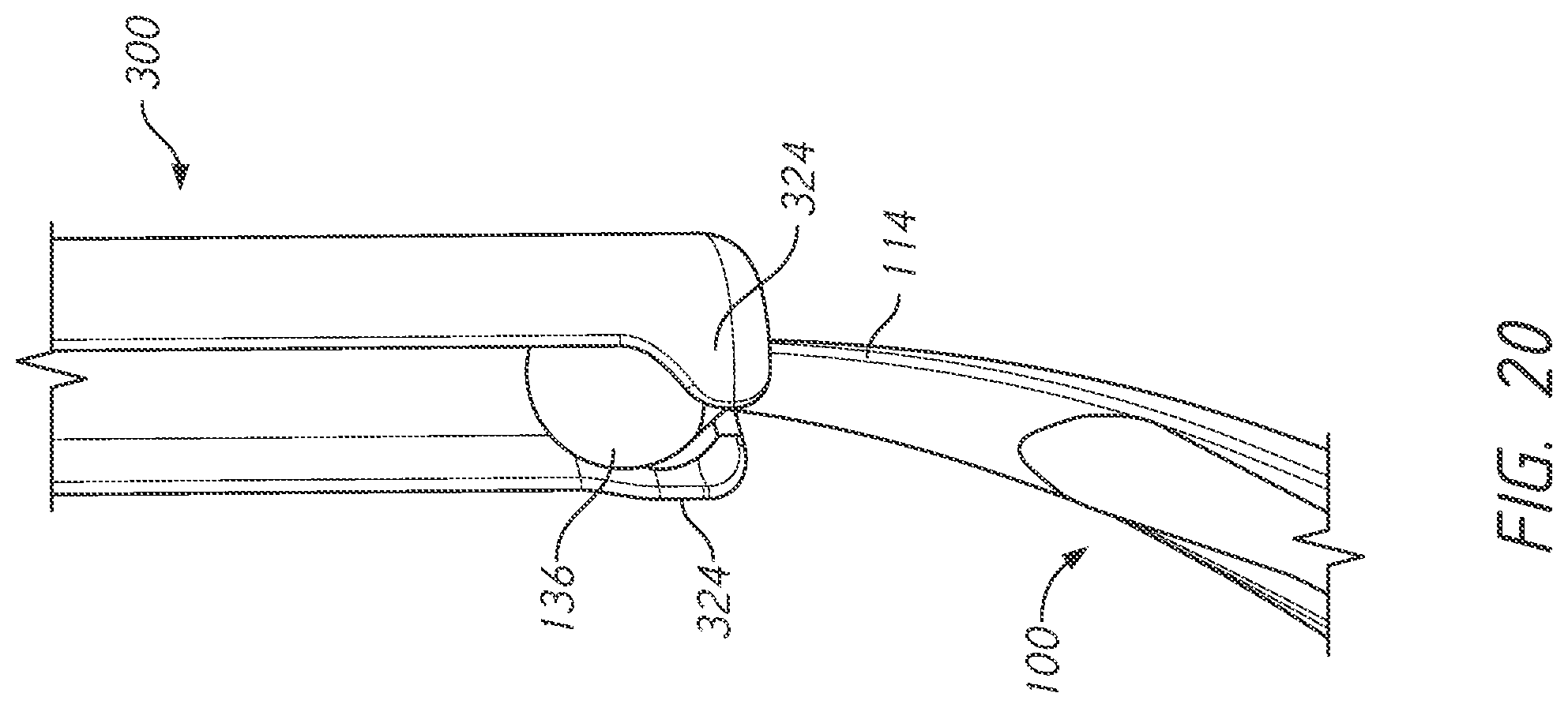
D00021

D00022

D00023

D00024

D00025

D00026

D00027

D00028

D00029

D00030

D00031

D00032

D00033

D00034

D00035

D00036
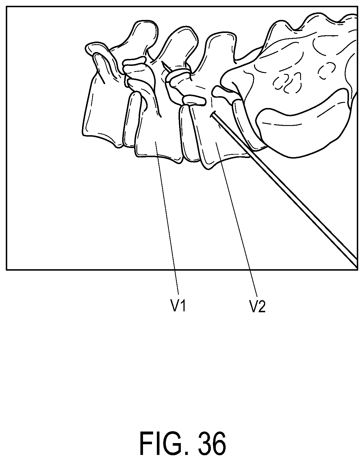
D00037

D00038

XML
uspto.report is an independent third-party trademark research tool that is not affiliated, endorsed, or sponsored by the United States Patent and Trademark Office (USPTO) or any other governmental organization. The information provided by uspto.report is based on publicly available data at the time of writing and is intended for informational purposes only.
While we strive to provide accurate and up-to-date information, we do not guarantee the accuracy, completeness, reliability, or suitability of the information displayed on this site. The use of this site is at your own risk. Any reliance you place on such information is therefore strictly at your own risk.
All official trademark data, including owner information, should be verified by visiting the official USPTO website at www.uspto.gov. This site is not intended to replace professional legal advice and should not be used as a substitute for consulting with a legal professional who is knowledgeable about trademark law.