Tissue specimen retrieval device with assisted deployment
Baril , et al. April 19, 2
U.S. patent number 11,304,714 [Application Number 16/878,423] was granted by the patent office on 2022-04-19 for tissue specimen retrieval device with assisted deployment. This patent grant is currently assigned to Covidien LP. The grantee listed for this patent is Covidien LP. Invention is credited to Saumya Banerjee, Jacob C. Baril, Matthew A. Dinino, Roy J. Pilletere, Justin J. Thomas.


| United States Patent | 11,304,714 |
| Baril , et al. | April 19, 2022 |
Tissue specimen retrieval device with assisted deployment
Abstract
A tissue specimen retrieval device includes a first shaft having a pair of slots defined in a distal end thereof and a pair of windows defined proximally of the pair of respective slots. A second shaft is included having a bag brim attached thereto, the second shaft telescopically movable within the first shaft between a retracted position, wherein the bag brim is disposed within the first shaft and a partially deployed position wherein the bag brim partially deploys from the first shaft forming an enclosure for supporting the tissue bag thereon. A pair of hook members is included each having an arm, a first end engaged to the bag brim and a free end including a hook at a distal end thereof. Upon deployment, the hook of each hook member engages a respective window allowing each respective arm to pivot outwardly within respective slots to fully deploy the bag brim.
| Inventors: | Baril; Jacob C. (Norwalk, CT), Banerjee; Saumya (Hamden, CT), Thomas; Justin J. (New Haven, CT), Pilletere; Roy J. (North Haven, CT), Dinino; Matthew A. (Newington, CT) | ||||||||||
|---|---|---|---|---|---|---|---|---|---|---|---|
| Applicant: |
|
||||||||||
| Assignee: | Covidien LP (Mansfield,
MA) |
||||||||||
| Family ID: | 1000006249954 | ||||||||||
| Appl. No.: | 16/878,423 | ||||||||||
| Filed: | May 19, 2020 |
Prior Publication Data
| Document Identifier | Publication Date | |
|---|---|---|
| US 20210361307 A1 | Nov 25, 2021 | |
| Current U.S. Class: | 1/1 |
| Current CPC Class: | A61B 17/221 (20130101); A61B 2017/00991 (20130101); A61B 2017/2212 (20130101); A61B 2017/00986 (20130101) |
| Current International Class: | A61B 17/221 (20060101); A61B 17/00 (20060101) |
| Field of Search: | ;606/127,110,113,114,200,151 |
References Cited [Referenced By]
U.S. Patent Documents
| 5846260 | December 1998 | Maahs |
| 6059793 | May 2000 | Pagedas |
| 6156055 | December 2000 | Ravenscroft |
| 6162209 | December 2000 | Gobron et al. |
| 6171317 | January 2001 | Jackson et al. |
| 6206889 | March 2001 | Bennardo |
| 6224612 | May 2001 | Bates et al. |
| 6228095 | May 2001 | Dennis |
| 6248113 | June 2001 | Fina |
| 6258102 | July 2001 | Pagedas |
| 6264663 | July 2001 | Cano |
| 6270505 | August 2001 | Yoshida et al. |
| 6280451 | August 2001 | Bates et al. |
| 6344026 | February 2002 | Burbank et al. |
| 6350266 | February 2002 | White et al. |
| 6350267 | February 2002 | Stefanchik |
| 6358198 | March 2002 | Levin et al. |
| 6368328 | April 2002 | Chu et al. |
| 6383195 | May 2002 | Richard |
| 6383197 | May 2002 | Conlon et al. |
| 6387102 | May 2002 | Pagedas |
| 6406440 | June 2002 | Stefanchik |
| 6409733 | June 2002 | Conlon et al. |
| 6447523 | September 2002 | Middleman et al. |
| 6530923 | March 2003 | Dubrul et al. |
| 6537273 | March 2003 | Sosiak et al. |
| 6752822 | June 2004 | Jespersen |
| 6805699 | October 2004 | Shimm |
| 6951533 | October 2005 | Foley |
| 6986774 | January 2006 | Middleman et al. |
| 7037275 | May 2006 | Marshall et al. |
| 7052501 | May 2006 | McGuckin, Jr. |
| 7087062 | August 2006 | Dhindsa |
| 7101379 | September 2006 | Gregory, Jr. et al. |
| 7101380 | September 2006 | Khachin et al. |
| 7112172 | September 2006 | Orban, III et al. |
| 7115125 | October 2006 | Nakao et al. |
| 7144400 | December 2006 | Byrum et al. |
| 7169154 | January 2007 | Que et al. |
| 7229418 | June 2007 | Burbank et al. |
| 7285126 | October 2007 | Sepetka et al. |
| 7316692 | January 2008 | Huffmaster |
| 7357801 | April 2008 | Burbank et al. |
| 7534252 | May 2009 | Sepetka et al. |
| 7547310 | June 2009 | Whitfield |
| 7615013 | November 2009 | Clifford et al. |
| 7618437 | November 2009 | Nakao |
| 7654283 | February 2010 | Seto et al. |
| 7670346 | March 2010 | Whitfield |
| 7678118 | March 2010 | Bates et al. |
| 7722626 | May 2010 | Middleman et al. |
| 7727227 | June 2010 | Teague et al. |
| 7731722 | June 2010 | Lavelle et al. |
| 7731723 | June 2010 | Kear et al. |
| 7762959 | July 2010 | Bilsbury |
| 7762960 | July 2010 | Timberlake et al. |
| 7875038 | January 2011 | Que et al. |
| 7892242 | February 2011 | Goldstein |
| 7914540 | March 2011 | Schwartz et al. |
| 7918860 | April 2011 | Leslie et al. |
| 7955292 | June 2011 | Leroy et al. |
| 8057485 | November 2011 | Hollis et al. |
| 8075567 | December 2011 | Taylor et al. |
| 8118816 | February 2012 | Teague |
| 8152820 | April 2012 | Mohamed et al. |
| 8172772 | May 2012 | Zwolinsk et al. |
| 8211115 | July 2012 | Cheng et al. |
| 8282572 | October 2012 | Bilsbury |
| 8337510 | December 2012 | Rieber et al. |
| 8348827 | January 2013 | Zwolinski |
| 8409216 | April 2013 | Parihar et al. |
| 8414596 | April 2013 | Parihar et al. |
| 8419749 | April 2013 | Shelton, IV et al. |
| 8425533 | April 2013 | Parihar et al. |
| 8430826 | April 2013 | Uznanski et al. |
| 8435237 | May 2013 | Bahney |
| 8444655 | May 2013 | Parihar et al. |
| 8486087 | July 2013 | Fleming |
| 8512351 | August 2013 | Teague |
| 8579914 | November 2013 | Menn et al. |
| 8585712 | November 2013 | O'Prey et al. |
| 8591521 | November 2013 | Cherry et al. |
| 8652147 | February 2014 | Hart |
| 8721658 | May 2014 | Kahle et al. |
| 8734464 | May 2014 | Grover et al. |
| 8777961 | July 2014 | Cabrera et al. |
| 8795291 | August 2014 | Davis et al. |
| 8821377 | September 2014 | Collins |
| 8827968 | September 2014 | Taylor et al. |
| 8870894 | October 2014 | Taylor et al. |
| 8906035 | December 2014 | Zwolinski et al. |
| 8956370 | February 2015 | Taylor et al. |
| 8968329 | March 2015 | Cabrera |
| 8986321 | March 2015 | Parihar et al. |
| 9005215 | April 2015 | Grover et al. |
| 9017328 | April 2015 | Bahney |
| 9017340 | April 2015 | Davis |
| 9033995 | May 2015 | Taylor et al. |
| 9084588 | July 2015 | Farascioni |
| 9101342 | August 2015 | Saleh |
| 9113848 | August 2015 | Fleming et al. |
| 9113849 | August 2015 | Davis |
| 9308008 | April 2016 | Duncan et al. |
| 9364201 | June 2016 | Orban, III |
| 9364202 | June 2016 | Menn et al. |
| 9370341 | June 2016 | Ceniccola et al. |
| 9370378 | June 2016 | O'Prey et al. |
| 9375224 | June 2016 | Jansen |
| 9414817 | August 2016 | Taylor et al. |
| 9468542 | October 2016 | Hurley et al. |
| 9486188 | November 2016 | Secrest et al. |
| 9522034 | December 2016 | Johnson et al. |
| 9549747 | January 2017 | Carlson |
| 9579115 | February 2017 | Kahle et al. |
| 9592067 | March 2017 | Hartoumbekis |
| 9622730 | April 2017 | Farascioni |
| 9624638 | April 2017 | Lebreton et al. |
| 9629618 | April 2017 | Davis et al. |
| 9655644 | May 2017 | Collins |
| 9730716 | August 2017 | Secrest et al. |
| 9789268 | October 2017 | Hart et al. |
| 9808228 | November 2017 | Kondrup et al. |
| 9826997 | November 2017 | Cherry et al. |
| 9867600 | January 2018 | Parihar et al. |
| 9877893 | January 2018 | Taylor et al. |
| 2005/0267492 | December 2005 | Poncet |
Assistant Examiner: Rwego; Kankindi
Attorney, Agent or Firm: Carter, DeLuca & Farrell LLP
Claims
What is claimed is:
1. A tissue specimen retrieval device, comprising: a first shaft including a pair of elongated slots defined in a distal end thereof and a pair of corresponding windows defined proximally of the pair of respective slots; a second shaft including a bag brim attached thereto, the second shaft telescopically movable within the first shaft between a retracted position, wherein the bag brim is disposed within the first shaft and a partially deployed position wherein the bag brim at least partially deploys distally from the first shaft forming a substantially circular enclosure for supporting a tissue specimen bag thereon; and a pair of hook members each having an arm, a first end operably engaged to the bag brim and a free end including a hook at a distal end thereof, wherein, upon deployment, the hook of each hook member engages a respective window defined in the first shaft allowing each respective arm of each hook member to pivot outwardly within respective slots defined within the first shaft member to fully deploy the bag brim.
2. The tissue specimen retrieval device according to claim 1, wherein the hook members are attached to opposing sides of the bag brim.
3. The tissue specimen retrieval device according to claim 1, wherein the bag brim is made from a material selected from a group consisting of polymers, plastics, composite materials, surgical stainless steel, and aluminum.
4. The tissue specimen retrieval device according to claim 1, wherein each hook member is attached to the bag brim by a rivet.
5. The tissue specimen retrieval device according to claim 1, wherein the hook of each hook member includes geometry to facilitate removal from each window upon retraction of the bag brim within the first shaft.
6. A tissue specimen retrieval device, comprising: a first shaft including a pair of elongated slots defined in a distal end thereof and a pair of corresponding windows defined proximally of the pair of respective slots; a second shaft including a bag brim attached thereto, the second shaft telescopically movable within the first shaft between a retracted position, wherein the bag brim is disposed within the first shaft and a first deployed position wherein the bag brim at least partially deploys distally from the first shaft forming a substantially circular enclosure for supporting an open end of a tissue specimen bag thereon; and a pair of hook members each having an arm, a first end operably engaged to the bag brim and a free end including a hook at a distal end thereof, wherein, upon deployment from the first deployed position to a second deployed position, the hook of each hook member engages a respective window defined in the first shaft allowing each respective arm of each hook member to pivot outwardly within respective slots defined within the first shaft member to more fully deploy the bag brim and maximize the open end of the tissue specimen bag.
7. The tissue specimen retrieval device according to claim 6, wherein the hook members are attached to opposing sides of the bag brim.
8. The tissue specimen retrieval device according to claim 6, wherein the bag brim is made from a material selected from a group consisting of polymers, plastics, composite materials, surgical stainless steel, and aluminum.
9. The tissue specimen retrieval device according to claim 6, wherein each hook member is attached to the bag brim by a rivet.
10. The tissue specimen retrieval device according to claim 6, wherein the hook of each hook member includes geometry to facilitate removal from each window upon retraction of the bag brim within the first shaft.
Description
BACKGROUND
Technical Field
The present disclosure relates to tissue specimen retrieval from an internal body cavity and, more particularly, to tissue specimen retrieval devices and methods to facilitate retrieval of a tissue specimen from an internal body cavity.
Background of Related Art
In minimally-invasive surgical procedures, operations are carried out within an internal body cavity through small entrance openings in the body. The entrance openings may be natural passageways of the body or may be surgically created, for example, by making a small incision into which an access device is inserted.
Minimally-invasive surgical procedures may be used for partial or total retrieval of a tissue specimen from an internal body cavity. However, the restricted access provided by minimally-invasive openings (natural passageways and/or surgically created openings) presents challenges with respect to maneuverability and visualization. The restricted access also presents challenges when the tissue specimen is required to be removed. As such, a tissue specimen that is deemed too large for intact retrieval may be broken down into a plurality of smaller pieces to facilitate retrieval from the internal body cavity.
During such minimally-invasive surgical procedures, it is common that a cyst, tumor, or other affected tissue specimen is required to be removed. In these and other procedures where cancerous tissue is required to be removed, retrieval of the tissue specimen in an enclosed environment is highly desirable to inhibit seeding of cancer cells. Thus, with respect to breaking down large tissue specimens for retrieval through minimally-invasive openings, there is the added challenge of doing so within an enclosed environment. As a result, various specimen retrieval devices have been developed. These devices are typically made from shape memory alloys (e.g., Nitinol.RTM.) that are configured to facilitate deployment of the specimen bag and bag brim for specimen retrieval. However, these materials tend to be expensive compared to stainless steel and other materials.
Moreover, specimen retrieval devices often come from the manufacturer preloaded with a bag brim of a specific diameter which in most cases is over-sized for the tissue specimen.
SUMMARY
As used herein, the term "distal" refers to the portion that is described which is further from a user, while the term "proximal" refers to the portion that is being described which is closer to a user. The terms "substantially" and "approximately," as utilized herein, account for industry-accepted material, manufacturing, measurement, use, and/or environmental tolerances. Further, any or all of the aspects and features described herein, to the extent consistent, may be used in conjunction with any or all of the other aspects and features described herein.
Provided in accordance with aspects of the present disclosure is a tissue specimen retrieval device including a first shaft having a pair of elongated slots defined in a distal end thereof and a pair of corresponding windows defined proximally of the pair of respective slots. A second shaft is included having a bag brim attached thereto, the second shaft telescopically movable within the first shaft between a retracted position, wherein the bag brim is disposed within the first shaft and a partially deployed position wherein the bag brim at least partially deploys distally from the first shaft forming a substantially circular enclosure for supporting the tissue specimen bag thereon. A pair of hook members is included each having an arm, a first end operably engaged to the bag brim and a free end including a hook at a distal end thereof. Upon deployment, the hook of each hook member engages a respective window defined in the first shaft allowing each respective arm of each hook member to pivot outwardly within respective slots defined within the first shaft member to fully deploy the bag brim.
In aspects according to the present disclosure, the hook members are attached to opposing sides of the bag brim. In other aspects according to the present disclosure, the bag brim is made from a material selected from a group consisting of polymers, plastics, composite materials, surgical stainless steel, and aluminum.
In aspects according to the present disclosure, each hook member is attached to the bag brim by a rivet. In other aspects according to the present disclosure, the hook of each hook member includes geometry to facilitate removal from each window upon retraction of the bag brim within the first shaft.
Provided in accordance with aspects of the present disclosure is a tissue specimen retrieval device including a first shaft having a pair of elongated slots defined in a distal end thereof and a pair of corresponding windows defined proximally of the pair of respective slots. A second shaft is included having a bag brim attached thereto, the second shaft telescopically movable within the first shaft between a retracted position, wherein the bag brim is disposed within the first shaft and a first deployed position wherein the bag brim at least partially deploys distally from the first shaft forming a substantially circular enclosure for supporting an open end of the tissue specimen bag thereon. A pair of hook members is included each having an arm, a first end operably engaged to the bag brim and a free end including a hook at a distal end thereof. Upon deployment from the first deployed position to a second deployed position, the hook of each hook member engages a respective window defined in the first shaft allowing each respective arm of each hook member to pivot outwardly within respective slots defined within the first shaft member to more fully deploy the bag brim and maximize the open end of the tissue specimen bag.
In aspects according to the present disclosure, the hook members are attached to opposing sides of the bag brim. In other aspects according to the present disclosure, the bag brim is made from a material selected from a group consisting of polymers, plastics, composite materials, surgical stainless steel, and aluminum.
In aspects according to the present disclosure, each hook member is attached to the bag brim by a rivet. In other aspects according to the present disclosure, the hook of each hook member includes geometry to facilitate removal from each window upon retraction of the bag brim within the first shaft.
BRIEF DESCRIPTION OF THE DRAWINGS
The above and other aspects and features of the present disclosure will become more apparent in view of the following detailed description when taken in conjunction with the accompanying drawings wherein like reference numerals identify similar or identical elements.
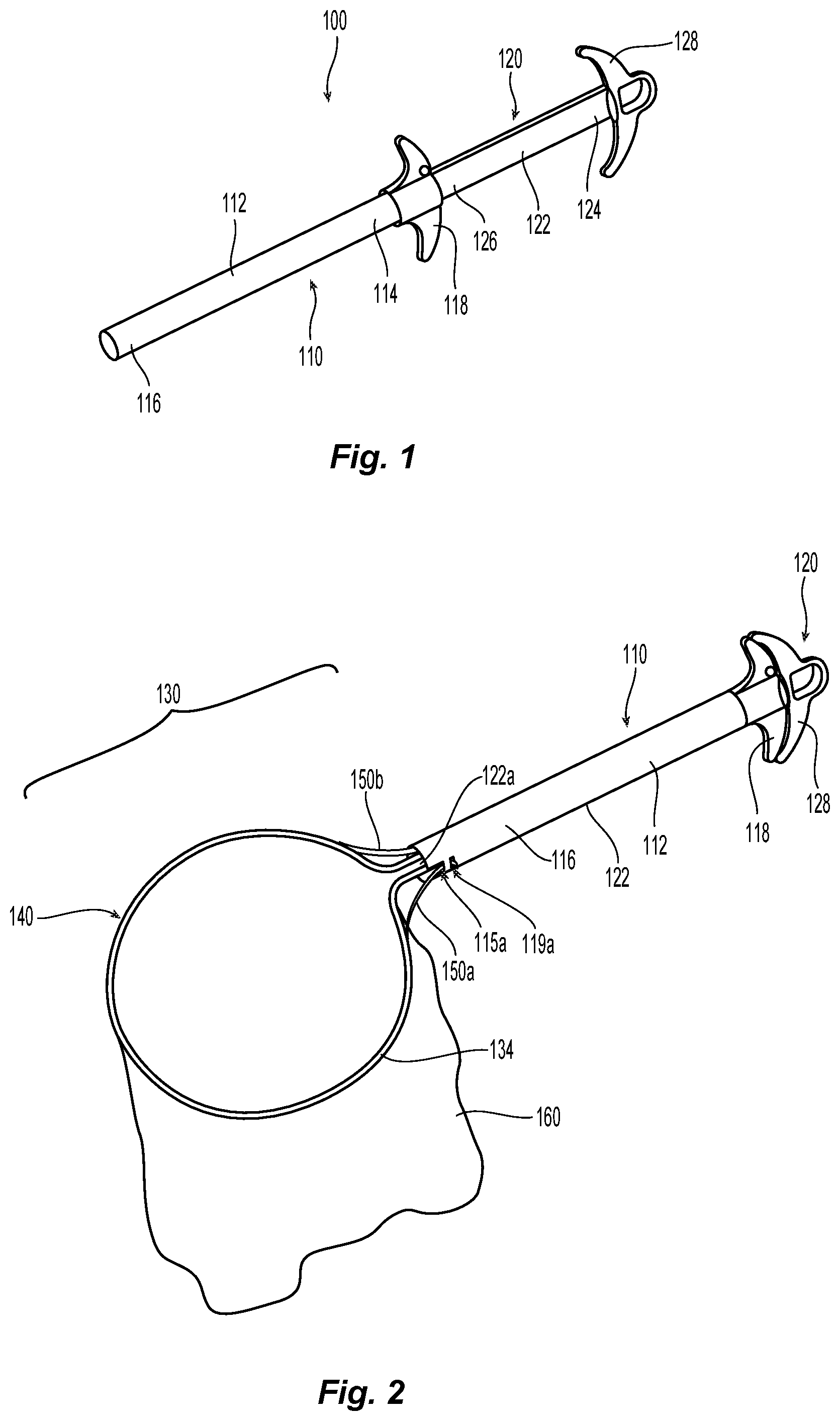
FIG. 1 is a perspective view of a tissue specimen retrieval device provided in accordance with aspects of the present disclosure, showing a bag brim disposed in a retracted position within the tissue specimen outer shaft;
FIG. 2 is a perspective view of the tissue specimen retrieval device of FIG. 1, disposed in a deployed position showing a bag brim supporting a specimen bag;
FIG. 3A is a top, internal view of the tissue specimen retrieval device of FIG. 1 shown prior to deployment;
FIG. 3B is a top, internal view of the tissue specimen retrieval device of FIG. 1 shown during deployment;
FIG. 3C is a top, internal view of the tissue specimen retrieval device of FIG. 1 shown fully deployed;
FIG. 4 is an enlarged, perspective view of a distal end of the outer shaft of the tissue specimen retrieval device; and
FIG. 5 is an enlarged, perspective view showing a deployment hook for use with an arm of the bag brim to facilitate deployment of the tissue specimen device.
DETAILED DESCRIPTION
Turning to FIGS. 1-2, a tissue specimen retrieval device provided in accordance with the present disclosure is shown generally identified by reference numeral 100. Tissue specimen retrieval device 100 includes a first body 110, a second body 120, and an end effector assembly 130 including a bag brim 140 and a specimen bag 160. First body 110 includes a first shaft 112 defining a proximal end portion 114 and a distal end portion 116. First body 110 further includes a first handle 118 disposed at proximal end portion 114 of first shaft 112. First handle 118 may be engaged with proximal end portion 114 of first shaft 112, monolithically formed with proximal end portion 114 of first shaft 112, or otherwise secured thereto in any suitable manner that enables a user to grasp and manipulate first handle 118 to thereby control manipulation of first shaft 112.
Second body 120 includes a second shaft 122 defining a proximal end portion 124 and a distal end portion 126. Second shaft 122 supports end effector assembly 130 at distal end portion 126 of second shaft 122 and is telescopically slidably within and relative to first shaft 112 between a retracted position of tissue specimen retrieval device 100 (FIG. 1), wherein end effector assembly 130 is disposed within first shaft 112, and a deployed position of tissue specimen retrieval device 100 (FIG. 2), wherein end effector assembly 130 extends distally from first shaft 112 to deploy the bag brim 140 and specimen bag 160. Second body 120 further includes a second handle 128 disposed at proximal end portion 124 of second shaft 122. Second handle 128 may be engaged with proximal end portion 124 of second shaft 122, monolithically formed with proximal end portion 124 of second shaft 122, or otherwise secured thereto in any suitable manner that enables a user to grasp and manipulate second handle 128 to thereby control manipulation of second shaft 122. Second handle 128, more specifically, is movable relative to first handle 118 from a spaced-apart position (FIG. 1) to an approximated position (FIG. 2) to move tissue specimen retrieval device 100 from the retracted position (FIG. 1), wherein end effector assembly 130 is disposed within first shaft 112, to the deployed position (FIG. 2), wherein end effector assembly 130 extends distally from first shaft 112.
Referring to FIGS. 3A-3C, end effector assembly 130, as noted above, is supported at distal end portion 126 of second shaft 122. End effector assembly 130, more specifically, includes bag brim 140 extending distally from distal end portion 126 of second shaft 122 and a specimen bag 160 (FIG. 2) supported on the bag brim 140. Bag brim 140 includes a substantially circular arm 134 that extends from a distal face of shaft 122. Typically, bag brim 140 is made from a shape memory alloy (e.g., Nitinol.RTM.) that is configured to facilitate deployment of the bag brim 140 for specimen retrieval. Other types of materials may be cheaper to utilize for the bag brim 140, e.g., polymers, plastics, composite materials, surgical stainless steel, aluminum, etc., but need to be reinforced to insure reliable deployment. Moreover, the bag brim 140 may be designed to be substantially flat (e.g., thin, band-like material) to provide strength for supporting the specimen bag 160 while still being flexible to facilitate expansion and retraction thereof.
The presently disclosed end effector assembly 130 and bag brim 140 may be made from materials other than shape memory alloys (e.g., Nitinol.RTM.) while still promoting reliable and consistent deployment. For the purposes herein, the bag brim 140 is made from surgical stainless steel although other similar type materials are also envisioned.
Bag brim 140 is made from high yield stainless steel that may be heat treated after initial shaping. More specifically, arm 134 includes free ends 134a and 134b that operably engage distal end 126 of shaft 122 to form a band-like support for supporting the specimen bag 160. The bag brim 140, upon deployment from end 116 of shaft 112, is configured to open to a generally circular configuration. Generally, since stainless steel is not as reliable as Nitinol.RTM., the specimen bag 160 may not consistently deploy to a desired and/or useful configuration.
A pair of hook members 150a, 150b is included with the end effector assembly 130 to facilitate reliable and consistent deployment of the specimen bag 160 to a desired configuration. More particularly, in a retracted configuration (FIG. 3A), a distal end 154a, 154b of each respective hook member 150a, 150b is configured to rest against an inner peripheral surface of shaft 116. The opposite end of each hook member 150a, 150b is riveted or otherwise secured to the bag arm 134, e.g., by a rivet 152 (FIG. 5).
The distal end 116 of shaft 112 includes a pair of opposing slots 117a, 117b defined therealong extending proximally therefrom along with a corresponding pair of hook windows 119a, 119b defined proximally relative thereto. As explained in more detail below, slots 117a, 117b are configured to allow the respective arms 151a, 151b of each hook member 150a, 150b to pivot outwardly to facilitate deployment of the bag brim 140 when the distal end 154a, 154b of each hook member 150a, 150b is engaged within hook windows 119a, 199b.
In use, the bag brim 140 is initially disposed in a collapsed, retracted configuration within a distal end 116 of shaft 112 (FIG. 3A). In the retracted configuration, the bag brim 140 is collapsed to fit within the inner peripheral surface of shaft 112 and the distal ends 154a, 154b of hook members 150a, 150b are sandwiched between the distal end of shaft 122 and the inner peripheral surface of the distal end 116 of shaft 112.
Upon initial deployment, the shaft 122 is pushed relative to shaft 112 to expose the bag brim 140 from the distal end 116 of shaft 112. As mentioned above, the spring-like properties of the surgical steel of the bag brim 140 cause the bag brim 140 and specimen bag 160 to at least partially open upon deployment. As shaft 122 is continually pushed distally within shaft 112, the distal ends 154a, 154b of the hook members 150a, 150b are configured to engage respective hook windows 119a, 119b preventing further distal advancement of shaft 122 relative to shaft 112 (FIG. 3B).
Once the distal ends 154a, 154b of the hook members 150a, 150b are engaged, the arms 151a, 151b of the hook members 150a, 150b are free to rotate outwardly within respective slots 117a, 117b to force the bag brim 140 to deploy further and open the mouth of the specimen bag fully and to a more desirable configuration (FIG. 3C). The specimen bag is now fully deployed and ready for specimen containment.
Once a tissue specimen is captured within the specimen bag 160, handle 128 may be retracted or pulled proximally relative to handle 118 to pull arm 134 back within shaft 112 and reduce the diameter of the bag brim 140. The geometry of the distal ends 154a, 154b of the hook members 150a, 150b may be configured to cam out of the respective hook windows 119a, 119b during retraction of shaft 122 within the distal end 116 of shaft 112. Bag brim 140 may include features that close off the opening of the bag brim 140 when fully retracted. Other features may be included that sever the bag brim 140 from the bag 160 when fully retracted.
From the foregoing and with reference to the various drawings, those skilled in the art will appreciate that certain modifications can be made to the present disclosure without departing from the scope of the same. While several embodiments of the disclosure have been shown in the drawings, it is not intended that the disclosure be limited thereto, as it is intended that the disclosure be as broad in scope as the art will allow and that the specification be read likewise. Therefore, the above description should not be construed as limiting, but merely as exemplifications of particular embodiments. Those skilled in the art will envision other modifications within the scope and spirit of the claims appended hereto.
* * * * *
D00000
D00001
D00002
D00003
XML
uspto.report is an independent third-party trademark research tool that is not affiliated, endorsed, or sponsored by the United States Patent and Trademark Office (USPTO) or any other governmental organization. The information provided by uspto.report is based on publicly available data at the time of writing and is intended for informational purposes only.
While we strive to provide accurate and up-to-date information, we do not guarantee the accuracy, completeness, reliability, or suitability of the information displayed on this site. The use of this site is at your own risk. Any reliance you place on such information is therefore strictly at your own risk.
All official trademark data, including owner information, should be verified by visiting the official USPTO website at www.uspto.gov. This site is not intended to replace professional legal advice and should not be used as a substitute for consulting with a legal professional who is knowledgeable about trademark law.