Devices, systems, and methods for the treatment of vascular defects
Rosqueta , et al. April 19, 2
U.S. patent number 11,304,700 [Application Number 16/738,968] was granted by the patent office on 2022-04-19 for devices, systems, and methods for the treatment of vascular defects. This patent grant is currently assigned to COVIDIEN LP. The grantee listed for this patent is Covidien LP. Invention is credited to Jose Gonzalez, Gaurav Krishnamurthy, Patrick Quinn, Arturo Rosqueta, Eric Yu.


| United States Patent | 11,304,700 |
| Rosqueta , et al. | April 19, 2022 |
Devices, systems, and methods for the treatment of vascular defects
Abstract
Devices, systems, and methods for treating vascular defects are disclosed herein. One aspect of the present technology, for example, is directed toward an occlusive device that includes a first mesh having an expanded state in which it curves about a first axis to form a first band, and a second mesh having an expanded state in which it curves about a second axis different than the first axis to form a second band. The second band may be positioned radially inward of the first band such that the device includes first and second overlap regions in which the first band overlaps the second band.
| Inventors: | Rosqueta; Arturo (San Jose, CA), Krishnamurthy; Gaurav (Mountain View, CA), Gonzalez; Jose (Fremont, CA), Quinn; Patrick (Oakland, CA), Yu; Eric (San Francisco, CA) | ||||||||||
|---|---|---|---|---|---|---|---|---|---|---|---|
| Applicant: |
|
||||||||||
| Assignee: | COVIDIEN LP (Mansfield,
MA) |
||||||||||
| Family ID: | 1000006247614 | ||||||||||
| Appl. No.: | 16/738,968 | ||||||||||
| Filed: | January 9, 2020 |
Prior Publication Data
| Document Identifier | Publication Date | |
|---|---|---|
| US 20200138447 A1 | May 7, 2020 | |
Related U.S. Patent Documents
| Application Number | Filing Date | Patent Number | Issue Date | ||
|---|---|---|---|---|---|
| 15683627 | Aug 22, 2017 | 10675036 | |||
| Current U.S. Class: | 1/1 |
| Current CPC Class: | A61B 17/12163 (20130101); A61B 17/12172 (20130101); A61B 17/12113 (20130101); A61B 2017/1205 (20130101); A61B 17/12177 (20130101) |
| Current International Class: | A61B 17/12 (20060101) |
References Cited [Referenced By]
U.S. Patent Documents
| 5250071 | October 1993 | Palermo |
| 5354295 | October 1994 | Guglielmi et al. |
| 5645558 | July 1997 | Horton |
| 5669931 | September 1997 | Kupiecki et al. |
| 5725552 | March 1998 | Kotula et al. |
| 5733294 | March 1998 | Forber et al. |
| 5741333 | April 1998 | Frid |
| 5749891 | May 1998 | Ken et al. |
| 5749919 | May 1998 | Blanc |
| 5814062 | September 1998 | Sepetka et al. |
| 5911731 | June 1999 | Pham et al. |
| 5916235 | June 1999 | Guglielmi |
| 5925060 | July 1999 | Forber |
| 5928260 | July 1999 | Chin et al. |
| 5935148 | August 1999 | Villar et al. |
| 5944738 | August 1999 | Amplatz et al. |
| 5951599 | September 1999 | McCrory |
| 5964797 | October 1999 | Ho |
| 5976169 | November 1999 | Imran |
| 5980554 | November 1999 | Lenker et al. |
| 6022374 | February 2000 | Imran |
| 6033423 | March 2000 | Ken et al. |
| 6036720 | March 2000 | Abrams et al. |
| 6059812 | May 2000 | Clerc et al. |
| 6063070 | May 2000 | Eder |
| 6063104 | May 2000 | Villar et al. |
| 6086577 | July 2000 | Ken et al. |
| 6090125 | July 2000 | Horton |
| 6093199 | July 2000 | Brown et al. |
| 6096021 | August 2000 | Helm et al. |
| 6123715 | September 2000 | Amplatz |
| 6139564 | October 2000 | Teoh |
| 6152144 | November 2000 | Lesh et al. |
| 6159531 | December 2000 | Dang et al. |
| 6168615 | January 2001 | Ken et al. |
| 6168622 | January 2001 | Mazzocchi |
| 6309367 | October 2001 | Boock |
| 6344048 | February 2002 | Chin et al. |
| 6346117 | February 2002 | Greenhalgh |
| 6350270 | February 2002 | Roue |
| 6368339 | April 2002 | Amplatz |
| 6371980 | April 2002 | Rudakov et al. |
| 6375668 | April 2002 | Gifford et al. |
| 6383174 | May 2002 | Eder |
| 6391037 | May 2002 | Greenhalgh |
| 6428558 | August 2002 | Jones et al. |
| 6447531 | September 2002 | Amplatz |
| 6451050 | September 2002 | Rudakov et al. |
| 6454780 | September 2002 | Wallace |
| 6494884 | December 2002 | Gifford et al. |
| 6506204 | January 2003 | Mazzocchi |
| 6511468 | January 2003 | Cragg et al. |
| 6547804 | April 2003 | Porter et al. |
| 6551303 | April 2003 | Van et al. |
| 6579303 | June 2003 | Amplatz |
| 6585748 | July 2003 | Jeffree |
| 6589256 | July 2003 | Forber |
| 6589265 | July 2003 | Palmer et al. |
| 6599308 | July 2003 | Amplatz |
| 6602261 | August 2003 | Greene et al. |
| 6605101 | August 2003 | Schaefer et al. |
| 6605102 | August 2003 | Mazzocchi et al. |
| 6605111 | August 2003 | Bose et al. |
| 6613074 | September 2003 | Mitelberg et al. |
| 6626939 | September 2003 | Burnside et al. |
| 6635068 | October 2003 | Dubrul et al. |
| 6652556 | November 2003 | Vantassel et al. |
| 6666882 | December 2003 | Bose et al. |
| 6669721 | December 2003 | Bose et al. |
| 6682546 | January 2004 | Amplatz |
| 6689486 | February 2004 | Ho et al. |
| 6730108 | May 2004 | Van et al. |
| 6746468 | June 2004 | Sepetka et al. |
| 6746890 | June 2004 | Gupta et al. |
| 6780196 | August 2004 | Chin et al. |
| 6802851 | October 2004 | Jones et al. |
| 6811560 | November 2004 | Jones et al. |
| 6855153 | February 2005 | Saadat |
| 6855154 | February 2005 | Abdel-Gawwad |
| 6878384 | April 2005 | Cruise et al. |
| 6905503 | June 2005 | Gifford et al. |
| 6936055 | August 2005 | Ken et al. |
| 6991617 | January 2006 | Hektner et al. |
| 6994092 | February 2006 | Van et al. |
| 6994717 | February 2006 | Konya et al. |
| 7011671 | March 2006 | Welch |
| 7029487 | April 2006 | Greene et al. |
| 7083632 | August 2006 | Avellanet et al. |
| 7128073 | October 2006 | Van et al. |
| 7128736 | October 2006 | Abrams et al. |
| 7169177 | January 2007 | Obara |
| 7195636 | March 2007 | Avellanet et al. |
| 7229461 | June 2007 | Chin et al. |
| 7232461 | June 2007 | Ramer |
| 7326225 | February 2008 | Ferrera et al. |
| 7331980 | February 2008 | Dubrul et al. |
| 7419503 | September 2008 | Pulnev et al. |
| 7597704 | October 2009 | Frazier et al. |
| 7601160 | October 2009 | Richter |
| 7708754 | May 2010 | Balgobin et al. |
| 7879064 | February 2011 | Monstadt et al. |
| RE42625 | August 2011 | Guglielmi |
| 8043326 | October 2011 | Hancock et al. |
| 8142456 | March 2012 | Rosqueta et al. |
| 8211160 | July 2012 | Garrison et al. |
| 8333783 | December 2012 | Braun et al. |
| 8343167 | January 2013 | Henson |
| 8361104 | January 2013 | Jones et al. |
| 8361138 | January 2013 | Adams |
| 8425541 | April 2013 | Masters et al. |
| 8444668 | May 2013 | Jones |
| 8470013 | June 2013 | Duggal et al. |
| 8696701 | April 2014 | Becking |
| 8715317 | May 2014 | Janardhan et al. |
| 8747597 | June 2014 | Rosqueta |
| 8771294 | July 2014 | Sepetka |
| 8834515 | September 2014 | Win et al. |
| 8864790 | October 2014 | Strauss |
| 8906057 | December 2014 | Connor et al. |
| 8974512 | March 2015 | Aboytes et al. |
| 8998947 | April 2015 | Aboytes et al. |
| 9211202 | December 2015 | Strother et al. |
| 9486224 | November 2016 | Riina et al. |
| 9585669 | March 2017 | Becking |
| 9687245 | June 2017 | Molaei |
| 9713475 | July 2017 | Divino |
| 9833309 | December 2017 | Levi et al. |
| 9844380 | December 2017 | Furey |
| 9844382 | December 2017 | Aboytes et al. |
| 9855051 | January 2018 | Aboytes et al. |
| 9855052 | January 2018 | Aboytes |
| 9907684 | March 2018 | Connor et al. |
| 9962146 | May 2018 | Hebert et al. |
| 10028745 | July 2018 | Morsi |
| 10064627 | September 2018 | Aboytes |
| 10111670 | October 2018 | Lorenzo |
| 10130372 | November 2018 | Griffin |
| 2001/0000797 | May 2001 | Mazzocchi |
| 2001/0001835 | May 2001 | Greene et al. |
| 2002/0062145 | May 2002 | Rudakov et al. |
| 2002/0169473 | November 2002 | Sepetka et al. |
| 2002/0193812 | December 2002 | Patel et al. |
| 2002/0193813 | December 2002 | Helkowski et al. |
| 2003/0004533 | January 2003 | Dieck et al. |
| 2003/0004568 | January 2003 | Ken et al. |
| 2003/0018294 | January 2003 | Cox |
| 2003/0028209 | February 2003 | Teoh et al. |
| 2003/0040772 | February 2003 | Hyodoh et al. |
| 2003/0055440 | March 2003 | Jones et al. |
| 2003/0093111 | May 2003 | Ken et al. |
| 2003/0113478 | June 2003 | Dang et al. |
| 2003/0114918 | June 2003 | Garrison et al. |
| 2004/0064093 | April 2004 | Hektner et al. |
| 2004/0115164 | June 2004 | Pierce et al. |
| 2004/0161451 | August 2004 | Pierce et al. |
| 2004/0172056 | September 2004 | Guterman et al. |
| 2005/0085836 | April 2005 | Raymond |
| 2005/0222580 | October 2005 | Gifford et al. |
| 2005/0267511 | December 2005 | Marks et al. |
| 2005/0277978 | December 2005 | Greenhalgh |
| 2006/0034883 | February 2006 | Dang et al. |
| 2006/0052816 | March 2006 | Bates et al. |
| 2006/0064151 | March 2006 | Guterman et al. |
| 2006/0089618 | April 2006 | McFerran et al. |
| 2006/0116709 | June 2006 | Sepetka et al. |
| 2006/0116712 | June 2006 | Sepetka et al. |
| 2006/0116713 | June 2006 | Sepetka et al. |
| 2006/0116714 | June 2006 | Sepetka et al. |
| 2006/0155323 | July 2006 | Porter et al. |
| 2006/0190025 | August 2006 | Lehe et al. |
| 2006/0190070 | August 2006 | Dieck et al. |
| 2006/0200234 | September 2006 | Hines |
| 2006/0206140 | September 2006 | Shaolian et al. |
| 2006/0206198 | September 2006 | Churchwell et al. |
| 2006/0206199 | September 2006 | Churchwell et al. |
| 2006/0241686 | October 2006 | Ferrera et al. |
| 2006/0247680 | November 2006 | Amplatz et al. |
| 2006/0271162 | November 2006 | Vito et al. |
| 2007/0010850 | January 2007 | Balgobin et al. |
| 2007/0083226 | April 2007 | Buiser et al. |
| 2007/0100426 | May 2007 | Rudakov et al. |
| 2007/0167876 | July 2007 | Euteneuer et al. |
| 2007/0167877 | July 2007 | Euteneuer et al. |
| 2007/0167972 | July 2007 | Euteneuer et al. |
| 2007/0175536 | August 2007 | Monetti et al. |
| 2007/0179520 | August 2007 | West |
| 2007/0185442 | August 2007 | Euteneuer et al. |
| 2007/0185443 | August 2007 | Euteneuer et al. |
| 2007/0185444 | August 2007 | Euteneuer et al. |
| 2007/0185457 | August 2007 | Euteneuer et al. |
| 2007/0191924 | August 2007 | Rudakov |
| 2007/0219619 | September 2007 | Dieck et al. |
| 2007/0276426 | November 2007 | Euteneuer |
| 2007/0276427 | November 2007 | Euteneuer |
| 2007/0282373 | December 2007 | Ashby et al. |
| 2007/0288083 | December 2007 | Hines |
| 2008/0082176 | April 2008 | Slazas |
| 2008/0097508 | April 2008 | Jones |
| 2008/0114391 | May 2008 | Dieck et al. |
| 2008/0114436 | May 2008 | Dieck et al. |
| 2008/0125852 | May 2008 | Garrison et al. |
| 2008/0195139 | August 2008 | Donald |
| 2008/0200945 | August 2008 | Amplatz et al. |
| 2008/0200979 | August 2008 | Dieck et al. |
| 2008/0221600 | September 2008 | Dieck et al. |
| 2008/0281350 | November 2008 | Sepetka et al. |
| 2009/0043375 | February 2009 | Rudakov et al. |
| 2009/0062841 | March 2009 | Amplatz et al. |
| 2009/0062899 | March 2009 | Dang et al. |
| 2009/0112251 | April 2009 | Qian et al. |
| 2009/0187214 | July 2009 | Amplatz et al. |
| 2009/0264978 | October 2009 | Dieck et al. |
| 2009/0275974 | November 2009 | Marchand et al. |
| 2009/0287291 | November 2009 | Becking et al. |
| 2009/0287292 | November 2009 | Becking et al. |
| 2009/0287294 | November 2009 | Rosqueta et al. |
| 2009/0297582 | December 2009 | Meyer et al. |
| 2009/0318892 | December 2009 | Aboytes et al. |
| 2009/0318941 | December 2009 | Sepetka et al. |
| 2009/0319023 | December 2009 | Hildebrand et al. |
| 2010/0030200 | February 2010 | Strauss et al. |
| 2010/0036410 | February 2010 | Krolik et al. |
| 2010/0139465 | June 2010 | Christian et al. |
| 2010/0144895 | June 2010 | Porter |
| 2010/0174269 | July 2010 | Tompkins et al. |
| 2010/0185271 | July 2010 | Zhang |
| 2010/0256527 | October 2010 | Lippert et al. |
| 2010/0256528 | October 2010 | Lippert et al. |
| 2010/0256601 | October 2010 | Lippert et al. |
| 2010/0256602 | October 2010 | Lippert et al. |
| 2010/0256603 | October 2010 | Lippert et al. |
| 2010/0256604 | October 2010 | Lippert et al. |
| 2010/0256605 | October 2010 | Lippert et al. |
| 2010/0256606 | October 2010 | Lippert et al. |
| 2010/0262014 | October 2010 | Huang |
| 2010/0268201 | October 2010 | Tieu et al. |
| 2011/0022149 | January 2011 | Cox et al. |
| 2011/0046658 | February 2011 | Connor et al. |
| 2011/0077620 | March 2011 | Debeer |
| 2011/0137332 | June 2011 | Sepetka et al. |
| 2011/0137405 | June 2011 | Wilson et al. |
| 2011/0144669 | June 2011 | Becking et al. |
| 2011/0152993 | June 2011 | Marchand et al. |
| 2011/0202085 | August 2011 | Loganathan et al. |
| 2011/0208227 | August 2011 | Becking |
| 2011/0224776 | September 2011 | Sepetka et al. |
| 2011/0265943 | November 2011 | Rosqueta et al. |
| 2011/0319926 | December 2011 | Becking et al. |
| 2012/0022572 | January 2012 | Braun et al. |
| 2012/0041472 | February 2012 | Tan et al. |
| 2012/0101510 | April 2012 | Lenker et al. |
| 2012/0116350 | May 2012 | Strauss et al. |
| 2012/0165919 | June 2012 | Cox et al. |
| 2012/0197283 | August 2012 | Marchand et al. |
| 2012/0239074 | September 2012 | Aboytes et al. |
| 2012/0283769 | November 2012 | Cruise et al. |
| 2012/0316598 | December 2012 | Becking et al. |
| 2012/0316632 | December 2012 | Gao |
| 2012/0330341 | December 2012 | Becking et al. |
| 2012/0330347 | December 2012 | Becking et al. |
| 2012/0330348 | December 2012 | Strauss et al. |
| 2013/0066357 | March 2013 | Aboytes et al. |
| 2013/0066360 | March 2013 | Becking et al. |
| 2013/0085522 | April 2013 | Becking et al. |
| 2013/0116722 | May 2013 | Aboytes et al. |
| 2013/0253572 | September 2013 | Molaei et al. |
| 2013/0274866 | October 2013 | Cox et al. |
| 2014/0012307 | January 2014 | Franano et al. |
| 2014/0058420 | February 2014 | Hannes et al. |
| 2014/0316012 | October 2014 | Freyman et al. |
| 2014/0371734 | December 2014 | Truckai |
| 2015/0182227 | July 2015 | Le et al. |
| 2015/0209050 | July 2015 | Aboytes |
| 2015/0216684 | August 2015 | Enzmann et al. |
| 2015/0250628 | September 2015 | Monstadt et al. |
| 2015/0272590 | October 2015 | Aboytes et al. |
| 2015/0297240 | October 2015 | Divino et al. |
| 2015/0313737 | November 2015 | Tippett et al. |
| 2015/0327843 | November 2015 | Garrison |
| 2015/0342613 | December 2015 | Aboytes et al. |
| 2016/0022445 | January 2016 | Ruvalcaba et al. |
| 2016/0066921 | March 2016 | Seifert et al. |
| 2016/0135984 | May 2016 | Rudakov et al. |
| 2016/0206320 | July 2016 | Connor |
| 2016/0206321 | July 2016 | Connor |
| 2016/0262766 | September 2016 | Aboytes et al. |
| 2016/0317158 | November 2016 | Lorenzo |
| 2017/0150971 | June 2017 | Hines |
| 2017/0156903 | June 2017 | Shobayashi |
| 2017/0189035 | July 2017 | Porter |
| 2017/0224350 | August 2017 | Shimizu et al. |
| 2017/0266023 | September 2017 | Thomas |
| 2017/0281194 | October 2017 | Divino |
| 2017/0340333 | November 2017 | Badruddin et al. |
| 2017/0367708 | December 2017 | Mayer et al. |
| 2018/0036012 | February 2018 | Aboytes et al. |
| 2018/0049859 | February 2018 | Stoppenhagen et al. |
| 2018/0125501 | May 2018 | Aboytes |
| 2018/0125686 | May 2018 | Lu |
| 2018/0132859 | May 2018 | Aboytes |
| 2018/0132862 | May 2018 | Aboytes |
| 2018/0140305 | May 2018 | Connor |
| 2018/0161185 | June 2018 | Kresslein et al. |
| 2018/0193025 | July 2018 | Walzman |
| 2018/0193026 | July 2018 | Yang et al. |
| 2018/0206852 | July 2018 | Moeller |
| 2019/0053811 | February 2019 | Garza et al. |
| 2019/0059907 | February 2019 | Rosqueta |
| 2020/0138447 | May 2020 | Rosqueta |
| 2812012 | Mar 2012 | CA | |||
| 102011102933 | Dec 2012 | DE | |||
| 0717969 | Jun 1996 | EP | |||
| 1295563 | Mar 2003 | EP | |||
| 1813213 | Aug 2007 | EP | |||
| 2208483 | Jul 2010 | EP | |||
| 2609888 | Jul 2013 | EP | |||
| 2890306 | Jul 2015 | EP | |||
| 2890306 | Mar 2007 | FR | |||
| 2005261951 | Sep 2005 | JP | |||
| 2008521492 | Jun 2008 | JP | |||
| 2010523260 | Jul 2010 | JP | |||
| 9406502 | Mar 1994 | WO | |||
| 9409705 | May 1994 | WO | |||
| 9907294 | Feb 1999 | WO | |||
| 9929260 | Jun 1999 | WO | |||
| 0164112 | Sep 2001 | WO | |||
| 02054980 | Jul 2002 | WO | |||
| 02089863 | Nov 2002 | WO | |||
| 2005099634 | Oct 2005 | WO | |||
| 2006034149 | Mar 2006 | WO | |||
| 2007121405 | Oct 2007 | WO | |||
| 2008036156 | Mar 2008 | WO | |||
| 2008074027 | Jun 2008 | WO | |||
| 2009014528 | Jan 2009 | WO | |||
| 2010009019 | Jan 2010 | WO | |||
| 2010027363 | Mar 2010 | WO | |||
| 2010077599 | Jul 2010 | WO | |||
| 2011066962 | Jun 2011 | WO | |||
| 2011095966 | Aug 2011 | WO | |||
| 2012034135 | Mar 2012 | WO | |||
| 2013112944 | Aug 2013 | WO | |||
| 2013138615 | Sep 2013 | WO | |||
| 2014105932 | Jul 2014 | WO | |||
| 2013138615 | Sep 2014 | WO | |||
| 2017074411 | May 2017 | WO | |||
| 2018051187 | Mar 2018 | WO | |||
Other References
|
European Search Report dated Feb. 5, 2021; European Patent Application No. 18849224.3; 10 pages. cited by applicant. |
Primary Examiner: Severson; Ryan J.
Attorney, Agent or Firm: Fortem IP LLP Fox; Mary
Parent Case Text
CROSS-REFERENCE TO RELATED APPLICATION
This application is a continuation of U.S. patent application Ser. No. 15/683,627 filed Aug. 22, 2017, which is incorporated herein by reference in its entirety.
Claims
We claim:
1. An occlusive device for treating an aneurysm, wherein a neck of the aneurysm opens to a blood vessel, the device comprising: a first elongated mesh having a low-profile state for intravascular delivery to the aneurysm and an expanded state in which the first elongated mesh is curved about a first axis to form a first band, the first elongated mesh having a length and a generally constant width along the entire length; and a second elongated mesh having a low-profile state for intravascular delivery to the aneurysm and an expanded state in which the second elongated mesh is curved about a second axis to form a second band, wherein a distal end of the second elongated mesh is coupled to a proximal end of the first elongated mesh; wherein the second band is positioned radially inward of the first band such that the device includes first and second overlap regions in which the first band overlaps the second band, and wherein the first and second overlap regions are spaced apart from one another along a circumference of the first band.
2. The device of claim 1, wherein the first and second elongated meshes are self-expanding.
3. The device of claim 1, wherein the first and second bands together bound a generally spherical shape, and wherein the first and second bands conform to an interior geometry of the aneurysm when the device is positioned within the aneurysm.
4. The device of claim 1, wherein the device is configured to be positioned in the aneurysm in an expanded state such that the first or second overlap region is positioned at the neck of the aneurysm, thereby substantially covering the neck and reducing blood flow through the neck from a parent vessel.
5. The device of claim 1, wherein the first axis is generally perpendicular to the second axis.
6. The device of claim 1, wherein at least one of the first elongated mesh and the second elongated mesh is a braid.
7. The device of claim 1, wherein at least one of the first elongated mesh and the second elongated mesh is a flattened tubular braid.
8. The device of claim 1, wherein a proximal end of the first elongated mesh is configured to be detachably coupled to an elongated delivery member.
9. An occlusive device for treating an aneurysm, wherein a neck of the aneurysm opens to a blood vessel, the device comprising: a first elongated mesh strip having a low-profile state for intravascular delivery to the aneurysm and an expanded state in which the first elongated mesh strip is curved about a first axis to form a first band encircling at least a portion of a first opening; a second elongated mesh strip having a low-profile state for intravascular delivery to the aneurysm and an expanded state in which the second elongated mesh strip is curved about a second axis to form a second band encircling at least a portion of a second opening, wherein a distal end of the second elongated mesh strip is coupled to a proximal end of the first elongated mesh strip; and a third elongated mesh strip having a low-profile state for intravascular delivery to the aneurysm and an expanded state in which the third elongated mesh strip is curved about a third axis to form a third band encircling at least a portion of a third opening, wherein a distal end of the third elongated mesh strip is coupled to a proximal end of the second elongated mesh strip; wherein, when the device is in an expanded, unconstrained state, the first, second, and third openings are aligned with first, second, and third planes, respectively, and the first second and third planes are perpendicular to one another, and wherein the first strip has a length, and wherein the first elongated mesh strip has a generally constant width along the length.
10. The device of claim 9, wherein: the first, second, and third bands together bound a predetermined, three-dimensional shape, the first elongated mesh has first longitudinal side edges, the second elongated mesh is bound by second longitudinal side edges, the third elongated mesh is bound by third longitudinal side edges, and when the device is in the expanded state, the first, second, and third side edges are spaced apart from one another along at least a portion of their circumferential lengths such that the device includes openings at its outer surface.
11. The device of claim 9, wherein: the first, second, and third bands together bound a predetermined, three-dimensional shape, the first elongated mesh has first longitudinal side edges, the second elongated mesh is bound by second longitudinal side edges, and when the device is in the expanded state, the first and the second side edges contact one another along at least a portion of their circumferential lengths and/or overlap one another along at least a portion of their circumferential lengths such that the first, second, and third bands define a continuous outer surface of the three-dimensional shape.
12. The device of claim 9, wherein, when the device is in an expanded, unconstrained state, the third band is radially inward of the second band, and the second band is radially inward of the first band.
13. The device of claim 12, wherein, in the expanded state, the first band is an open band such that when the first band is viewed in cross section, it does not form a closed shape.
14. The device of claim 12, wherein, in the expanded state, the second band is an open band such that when the second band is viewed in cross section, it does not form a closed shape.
15. The device of claim 12, wherein, in the expanded state, the third band is an open band such that when the third band is viewed in cross section, it does not form a closed shape.
16. The device of claim 12, wherein, in the expanded state, the first band is a closed band such that when the first band is viewed in cross section, it forms a closed shape.
17. The device of claim 12, wherein, in the expanded state, the second band is a closed band such that when the second band is viewed in cross section, it forms a closed shape.
18. The device of claim 12, wherein, in the expanded state, the third band is a closed band such that when the third band is viewed in cross section, it forms a closed shape.
19. A method for treating an aneurysm with an occlusive device including a first elongated mesh and a second elongated mesh, wherein a neck of the aneurysm opens to a blood vessel, the method comprising: pushing the first elongated mesh distally from a delivery catheter into an interior region of the aneurysm, the first elongated mesh having a length and a generally constant width along the length, wherein pushing the first elongated mesh distally includes curving the first elongated mesh back on itself to form a first band that expands against and conforms to an inner surface of the aneurysm wall; pushing a second elongated mesh distally from the delivery catheter into the interior region of the aneurysm, wherein a distal end of the second elongated mesh is coupled to a proximal end of the first elongated mesh, and wherein pushing the second elongated mesh distally includes curving the second elongated mesh back on itself to form a second band that expands against and conforms to the inner surface of the aneurysm wall, wherein the first and second bands intersect at first and second overlap regions when the device is in an expanded state; and positioning the device within the aneurysm such that the first or second overlap region is positioned at the neck of the aneurysm, thereby substantially covering the neck and reducing blood flow from a parent vessel through the neck.
20. The method of claim 19, wherein the first elongated mesh is pushed distally from the delivery catheter before the second elongated mesh is pushed distally from the delivery catheter.
21. The method of claim 19, wherein: curving the first elongated mesh back on itself to form a first band includes curving the first elongated mesh around a first axis; and curving the second elongated mesh back on itself to form a second band includes curving the second elongated mesh around a second axis different than the first axis.
22. The method of claim 21, wherein the first axis is perpendicular to the second axis.
23. The method of claim 19, wherein the first and second elongated meshes are formed of a single, continuous elongated mesh.
24. The method of claim 19, further comprising pushing a third elongated mesh distally from the delivery catheter into the interior region of the aneurysm, wherein pushing the third elongated mesh distally includes curving the third elongated mesh back on itself to form a third band that expands against and conforms to the inner surface of the aneurysm wall.
Description
TECHNICAL FIELD
The present technology is directed generally to devices, systems, and methods for the treatment of vascular defects.
BACKGROUND
Aneurysms are blood-filled dilations of a blood vessel generally caused by disease or weakening of the blood vessel wall. The wall of the aneurysm may progressively thin, which increases the risk of rupture causing hemorrhagic stroke or even sudden death. There are about 30,000 to 40,000 cases of aneurysmal rupture per year in the United States, accounting for about 5% of all strokes. The prognosis after aneurysmal rupture is poor; the 30-day mortality rate is approximately 45% and a positive functional outcome is achieved in only 40-50% of survivors. Traditional approaches to preventing aneurysmal rupture often include packing the aneurysm with metal coils to reduce the inflow of blood to the aneurysm and prevent further enlargement and rupture. Such coils are often referred to as "embolic coils" or "microcoils," and can be categorized into the following three groups based on their structural properties: framing coils, filling coils, and finishing coils. Framing coils are inserted first into the aneurysm and form the base structure into which the later-delivered filling coils are packed. As such, framing coils are stiffer than filling and finishing coils to provide structural stability and generally have a complex or three-dimensional shape for approximating the periphery of the aneurysm. Filling coils, in contrast, are softer than framing coils, and multiple filling coils are packed within the framework of the framing coil(s) to achieve a high packing density. Finishing coils are delivered last to fill any remaining gaps left between filling coils.
Embolic coils, however, have several drawbacks. First, embolic coils generally only achieve a 20-40% packing density (i.e., ratio of the volume of the coils inserted into the aneurysm sac and the volume of the aneurysm sac). As a result, blood continues to flow into the aneurysm (also known as recanalization) in about 30% of coil cases, which can cause further swelling of the aneurysm over time. In addition, because the coils must be very small to fit within a microcatheter for delivery through the tiny cranial vessels, numerous coils are often required to adequately fill the aneurysm. These numerous coils must be delivered one-by-one, thereby increasing procedure time and complexity. Yet another drawback is that embolic coils cannot accommodate the wide range of aneurysm shapes and sizes. Embolic coils, for example, are difficult to stabilize within wide-necked aneurysms, which can result in migration of one or more coils across the neck such that a portion of the migrated coil(s) protrudes into the parent blood vessel. The protruding portion of the migrated coil(s) can be a nidus for thromboembolism, which can be fatal if left unaddressed. To address this shortcoming, many existing treatments include positioning an intracranial stent across the neck of the aneurysm to prevent all or part of a coil from migrating across the neck. However, intracranial stents can also be a nidus for thromboembolism, and further increase procedure time and cost. Thus, there is a need for improved devices, systems, and methods for treating aneurysms.
SUMMARY
The present technology is directed generally to devices, systems, and methods for the treatment of vascular defects, and in particular, to vascular occlusion devices for treating hemorrhagic stroke. In some embodiments, the present technology includes an expandable occlusion device comprising a mesh structure having a low-profile state for intravascular delivery to an aneurysm and an expanded state in which the mesh is configured to be positioned within the interior cavity of the aneurysm. As used herein, "mesh" or "mesh structure" may refer to a stent, a braid, a lattice, a weave, a laser-cut sheet, and/or any other suitable porous structures. In some embodiments, the occlusion device includes a mesh structure having two or more mesh portions that have different shapes and/or configurations. The mesh portions complement one another when positioned together within the aneurysm to stabilize and/or anchor the mesh within the aneurysm, fill space within the aneurysm, and/or seal the neck of the aneurysm to prevent or reduce blood flow therethrough.
The subject technology is illustrated, for example, according to various aspects described below. Various examples of aspects of the subject technology are described as numbered clauses (1, 2, 3, etc.) for convenience. These are provided as examples and do not limit the subject technology. It is noted that any of the dependent clauses may be combined in any combination, and placed into a respective independent clause, e.g., clause [1, 17, and 31]. The other clauses can be presented in a similar manner.
Clause 1. An occlusive device for treating an aneurysm, wherein a neck of the aneurysm opens to a blood vessel, the device comprising: a first elongated mesh having a low-profile state for intravascular delivery to the aneurysm and an expanded state in which the first elongated mesh is curved about a first axis to form a first band; and a second elongated mesh having a low-profile state for intravascular delivery to the aneurysm and an expanded state in which the second elongated mesh is curved about a second axis different than the first axis to form a second band, wherein the second band is positioned radially inward of the first band such that the device includes first and second overlap regions in which the first band overlaps the second band, and wherein the first and second overlap regions are spaced apart from one another along a circumference of the first band.
Clause 2. The device of Clause 1, wherein the first and second elongated meshes are self-expanding.
Clause 3. The device of Clause 1 or Clause 2, wherein the first and second bands together bound a generally spherical shape, and wherein the first and second bands conform to an interior geometry of the aneurysm when the device is positioned within the aneurysm.
Clause 4. The device of any one of Clauses 1-3, wherein the device is configured to be positioned in the aneurysm in an expanded state such that the first or second overlap region is positioned at the neck of the aneurysm, thereby substantially covering the neck and reducing blood flow through the neck from a parent vessel.
Clause 5. The device of any one of Clauses 1-4, wherein the first axis is generally perpendicular to the second axis.
Clause 6. The device of any one of Clauses 1-5, wherein each of the first and second bands have a generally constant width along their respective circumferential lengths.
Clause 7. The device of any one of Clauses 1-6, further comprising a third elongated mesh having a low-profile state for intravascular delivery to the aneurysm and an expanded state in which the third elongated mesh is curved about a third axis different than the first axis and the second axis to form a third band.
Clause 8. The device of any one of Clauses 1-7, wherein at least one of the first elongated mesh and the second elongated mesh is a braid.
Clause 9. The device of any one of Clauses 1-8, wherein at least one of the first elongated mesh and the second elongated mesh is a flattened tubular braid.
Clause 10. The device of any one of Clauses 1-9, wherein the device includes a flexible joint between a distal end of the first elongated mesh and a proximal end of the second elongated mesh.
Clause 11. The device of Clause 10, wherein the first elongated mesh and the second elongated mesh are formed of a single, continuous elongated mesh, and wherein the joint is a narrowed region of the mesh configured to direct a proximal portion of the second elongated mesh away from the first band when the device is in an expanded state.
Clause 12. The device of Clause 10, wherein the first elongated mesh and second elongated mesh are discrete, separate meshes, and wherein the joint is a coupler.
Clause 13. The device of any one of Clauses 1-12, wherein the first and second elongated meshes have at least two layers such that the first and second overlap regions of the device include at least four mesh layers.
Clause 14. The device of any one of Clauses 1-13, wherein a proximal end of the first elongated mesh is configured to be detachably coupled to an elongated delivery member.
Clause 15. The device of any one of Clauses 1-14, wherein a distal end of the second elongated mesh is coupled to an atraumatic lead-in member that extends distally from the second elongated mesh.
Clause 16. The device of any one of Clauses 1-15, wherein the device includes a plurality of openings between the first and second elongated meshes.
Clause 17. The device of any one of Clauses 1-16, wherein: the first and second bands together bound a predetermined, three-dimensional shape, the first elongated mesh has first longitudinal side edges, the second elongated mesh is bound by second longitudinal side edges, and when the device is in the expanded state, the first and the second side edges are spaced apart from one another along at least a portion of their circumferential lengths such that the device includes openings at its outer surface.
Clause 18. The device of any one of Clauses 1-16, wherein: the first and second bands together bound a predetermined, three-dimensional shape, the first elongated mesh has first longitudinal side edges, the second elongated mesh is bound by second longitudinal side edges, and when the device is in the expanded state, the first and the second side edges contact one another along at least a portion of their circumferential lengths and/or overlap one another along at least a portion of their circumferential lengths such that the first and second bands define a continuous outer surface of the three-dimensional shape.
Clause 19. The device of any one of Clauses 1-18, wherein, in the expanded state, the first band is an open band such that when the first band is viewed in cross section, it does not form a closed shape.
Clause 20. The device of any one of Clauses 1-19, wherein, in the expanded state, the second band is an open band such that when the second band is viewed in cross section, it does not form a closed shape.
Clause 21. The device of any one of Clauses 1-18 and 20, wherein, in the expanded state, the first band is a closed band such that when the first band is viewed in cross section, it forms a closed shape.
Clause 22. The device of any one of Clauses 1-19 and 21, wherein, in the expanded state, the second band is a closed band such that when the second band is viewed in cross section, it forms a closed shape.
Clause 23. The device of any one of Clauses 1-22, wherein the first and second bands together bound a predetermined, three-dimensional shape.
Clause 24. An occlusive device for treating an aneurysm, wherein a neck of the aneurysm opens to a blood vessel, the device comprising: a first elongated mesh strip having a low-profile state for intravascular delivery to the aneurysm and an expanded state in which the first elongated mesh strip is curved about a first axis to form a first band encircling at least a portion of a first opening; a second elongated mesh strip having a low-profile state for intravascular delivery to the aneurysm and an expanded state in which the second elongated mesh strip is curved about a second axis to form a second band encircling at least a portion of a second opening; and a third elongated mesh strip having a low-profile state for intravascular delivery to the aneurysm and an expanded state in which the third elongated mesh strip is curved about a third axis to form a third band encircling at least a portion of a third opening, wherein, when the device is in an expanded, unconstrained state, the first, second, and third openings are aligned with first, second, and third planes, respectively, and the first second and third planes are perpendicular to one another.
Clause 25. The device of Clause 24, wherein the first, second, and third elongated mesh strips are self-expanding.
Clause 26. The device of any one of Clause 24 or Clause 25, wherein the first, second, and third bands together bound a generally spherical shape, and wherein the first, second, and third bands conform to an interior geometry of the aneurysm when the device is positioned within the aneurysm.
Clause 27. The device of any one of Clauses 24-26, wherein the device includes: first and second overlap regions in which the first band intersects the second band; third and fourth overlap regions in which the first band intersects the third band; and fifth and sixth overlap regions in which the second band intersects the third band.
Clause 28. The device of Clause 27, wherein the device is configured to be positioned in the aneurysm in an expanded state such that at least one of the first-sixth overlap regions are positioned at the neck of the aneurysm, thereby substantially covering the neck and reducing blood flow from a parent vessel through the neck.
Clause 29. The device of any one of Clauses 24-28, wherein at least one of the first, second, and third elongated mesh strips is a braid.
Clause 30. The device of any one of Clauses 24-29, wherein at least one of the first, second, and third elongated mesh strips is a flattened tubular braid.
Clause 31. The device of any one of Clauses 24-30, wherein a distal end of the first elongated mesh strip is coupled to a proximal end of the second elongated mesh strip at a first joint, and a distal end of the second elongated mesh strip is coupled to a proximal end of the third elongated mesh strip at a second joint.
Clause 32. The device of any one of Clauses 24-31, wherein the third elongated mesh is configured to be released from a delivery catheter before the second elongated mesh, and the second elongated mesh is configured to be released from a delivery catheter before the first elongated mesh.
Clause 33. The device of any one of Clauses 24-32, wherein a proximal end of the first elongated mesh strip is configured to be detachably coupled to an elongated delivery member.
Clause 34. The device of any one of Clauses 24-33, wherein a distal end of the third elongated mesh strip is coupled to an atraumatic lead-in member that extends distally from the third elongated mesh.
Clause 35. The device of any one of Clauses 24-34, wherein, when the device is in an expanded, unconstrained state, the third band is radially inward of the second band, and the second band is radially inward of the first band.
Clause 36. The device of any one of Clauses 24-35, wherein the first, second, and third elongated mesh strips are formed of a single, continuous elongated mesh.
Clause 37. The device of any one of Clauses 24-35, wherein the first, second, and third elongated mesh strips are discrete, separate meshes.
Clause 38. The device of any one of Clauses 24-37, wherein: the first, second, and third bands together bound a predetermined, three-dimensional shape, the first elongated mesh has first longitudinal side edges, the second elongated mesh is bound by second longitudinal side edges, the third elongated mesh is bound by third longitudinal side edges, and when the device is in the expanded state, the first, second, and third side edges are spaced apart from one another along at least a portion of their circumferential lengths such that the device includes openings at its outer surface.
Clause 39. The device of any one of Clauses 24-37, wherein: the first, second, and third bands together bound a predetermined, three-dimensional shape, the first elongated mesh has first longitudinal side edges, the second elongated mesh is bound by second longitudinal side edges, and when the device is in the expanded state, the first and the second side edges contact one another along at least a portion of their circumferential lengths and/or overlap one another along at least a portion of their circumferential lengths such that the first, second, and third bands define a continuous outer surface of the three-dimensional shape.
Clause 40. The device of any one of Clauses 24-39, wherein, in the expanded state, the first band is an open band such that when the first band is viewed in cross section, it does not form a closed shape.
Clause 41. The device of any one of Clauses 24-40, wherein, in the expanded state, the second band is an open band such that when the second band is viewed in cross section, it does not form a closed shape.
Clause 42. The device of any one of Clauses 24-41, wherein, in the expanded state, the third band is an open band such that when the third band is viewed in cross section, it does not form a closed shape.
Clause 43. The device of any one of Clauses 24-39, 41, or 42, wherein, in the expanded state, the first band is a closed band such that when the first band is viewed in cross section, it forms a closed shape.
Clause 44. The device of any one of Clauses 24-40, 42, or 43, wherein, in the expanded state, the second band is a closed band such that when the second band is viewed in cross section, it forms a closed shape.
Clause 45. The device of any one of Clauses 24-41, 43, or 44, wherein, in the expanded state, the third band is a closed band such that when the third band is viewed in cross section, it forms a closed shape.
Clause 46. The device of any one of Clauses 24-45, wherein the first, second, and third bands together bound a predetermined, three-dimensional shape.
Clause 47. A method for treating an aneurysm with an occlusive device including a first elongated mesh and a second elongated mesh, wherein a neck of the aneurysm opens to a blood vessel, the method comprising: pushing the first elongated mesh distally from a delivery catheter into an interior region of the aneurysm, wherein pushing the first elongated mesh distally includes curving the first elongated mesh back on itself to form a first band that expands against and conforms to an inner surface of the aneurysm wall; pushing a second elongated mesh distally from the delivery catheter into the interior region of the aneurysm, wherein pushing the second elongated mesh distally includes curving the second elongated mesh back on itself to form a second band that expands against and conforms to the inner surface of the aneurysm wall, wherein the first and second bands intersect at first and second overlap regions when the device is in an expanded state; and positioning the device within the aneurysm such that the first or second overlap region is positioned at the neck of the aneurysm, thereby substantially covering the neck and reducing blood flow from a parent vessel through the neck.
Clause 48. The method of Clause 47, wherein the first elongated mesh is pushed distally from the delivery catheter before the second elongated mesh is pushed distally from the delivery catheter.
Clause 49. The method of Clause 47 or Clause 48, wherein: curving the first elongated mesh back on itself to form a first band includes curving the first elongated mesh around a first axis; and curving the second elongated mesh back on itself to form a second band includes curving the second elongated mesh around a second axis different than the first axis.
Clause 50. The method of Clause 49, wherein the first axis is perpendicular to the second axis.
Clause 51. The method of any one of Clauses 47-50, wherein the first and second elongated meshes are formed of a single, continuous elongated mesh.
Clause 52. The method of any one of Clauses 47-50, wherein the first and second elongated meshes are discrete, separate meshes.
Clause 53. The method of any one of Clauses 47-52, further comprising pushing a third elongated mesh distally from the delivery catheter into the interior region of the aneurysm, wherein pushing the third elongated mesh distally includes curving the third elongated mesh back on itself to form a third band that expands against and conforms to the inner surface of the aneurysm wall.
Clause 54. The method of Clause 53, wherein the third band is an open band.
Clause 55. The method of Clause 53, wherein the third band is a closed band.
Clause 56. The method of any one of Clauses 53-55, wherein: the first band intersects the third band at third and fourth overlap regions of the device, and the second band intersects the third band at fifth and sixth overlap regions of the device.
Clause 57. The method of Clause 56, further comprising positioning the device within the aneurysm such that one or more of the first-sixth overlap regions are positioned at the neck of the aneurysm.
Clause 58. The method of any one of Clauses 53-57, wherein: curving the first elongated mesh back on itself to form a first band includes curving the first elongated mesh around a first axis; curving the second elongated mesh back on itself to form a second band includes curving the second elongated mesh around a second axis different than the first axis; and curving the third elongated mesh back on itself to form a third band includes curving the third elongated mesh around a third axis different than the first and second axes.
Clause 59. The method of Clause 58, wherein the first, second, and third axes are perpendicular to one another.
Clause 60. The method of any one of Clauses 47-59, wherein the first band is an open band.
Clause 61. The method of any one of Clauses 47-59, wherein the first band is a closed band.
Clause 62. The method of any one of Clauses 47-61, wherein the second band is an open band.
Clause 63. The method of any one of Clauses 47-61, wherein the second band is a closed band.
Clause 64. A method for treating an aneurysm comprising positioning any one of the occlusive devices of Clauses 1-46 within an aneurysm.
Clause 64. A method for treating an aneurysm comprising positioning two or more of the occlusive devices of Clauses 1-46 within an aneurysm, in succession.
BRIEF DESCRIPTION OF THE DRAWINGS
FIG. 1A is an occlusion device in a deployed, relaxed state outside of an aneurysm according to some embodiments of the present technology.
FIG. 1B is a top view of the occlusion device shown in FIG. 1A, unfurled and held in an elongated configuration.
FIGS. 1C-1E are schematic representations of different band configurations according to some embodiments of the present technology.
FIG. 1F is a different view of the occlusion device of FIG. 1A in a deployed, relaxed state outside of an aneurysm and coupled to a delivery member according to some embodiments of the present technology.
FIGS. 2A and 2B are fluoroscopic images showing a method of deploying an occlusion device within a tall aneurysm in accordance with some embodiments of the present technology.
FIGS. 3A and 3B are fluoroscopic images showing a method of deploying an occlusion device within a wide aneurysm in accordance with some embodiments of the present technology.
FIG. 4A is an occlusion device in a deployed, relaxed state outside of an aneurysm according to some embodiments of the present technology.
FIG. 4B is an enlarged view of an articulation joint of the occlusion device shown in FIG. 4A according to some embodiments of the present technology.
FIGS. 5A and 5B are fluoroscopic images showing a method of deploying an occlusion device within a wide aneurysm in accordance with some embodiments of the present technology.
FIGS. 6A and 6B are fluoroscopic images showing a method of deploying an occlusion device within a tall aneurysm in accordance with some embodiments of the present technology.
FIG. 7A is an occlusion device in a deployed, relaxed state outside of an aneurysm according to some embodiments of the present technology.
FIG. 7B is an enlarged view of an articulation joint of the occlusion device shown in FIG. 7A according to some embodiments of the present technology.
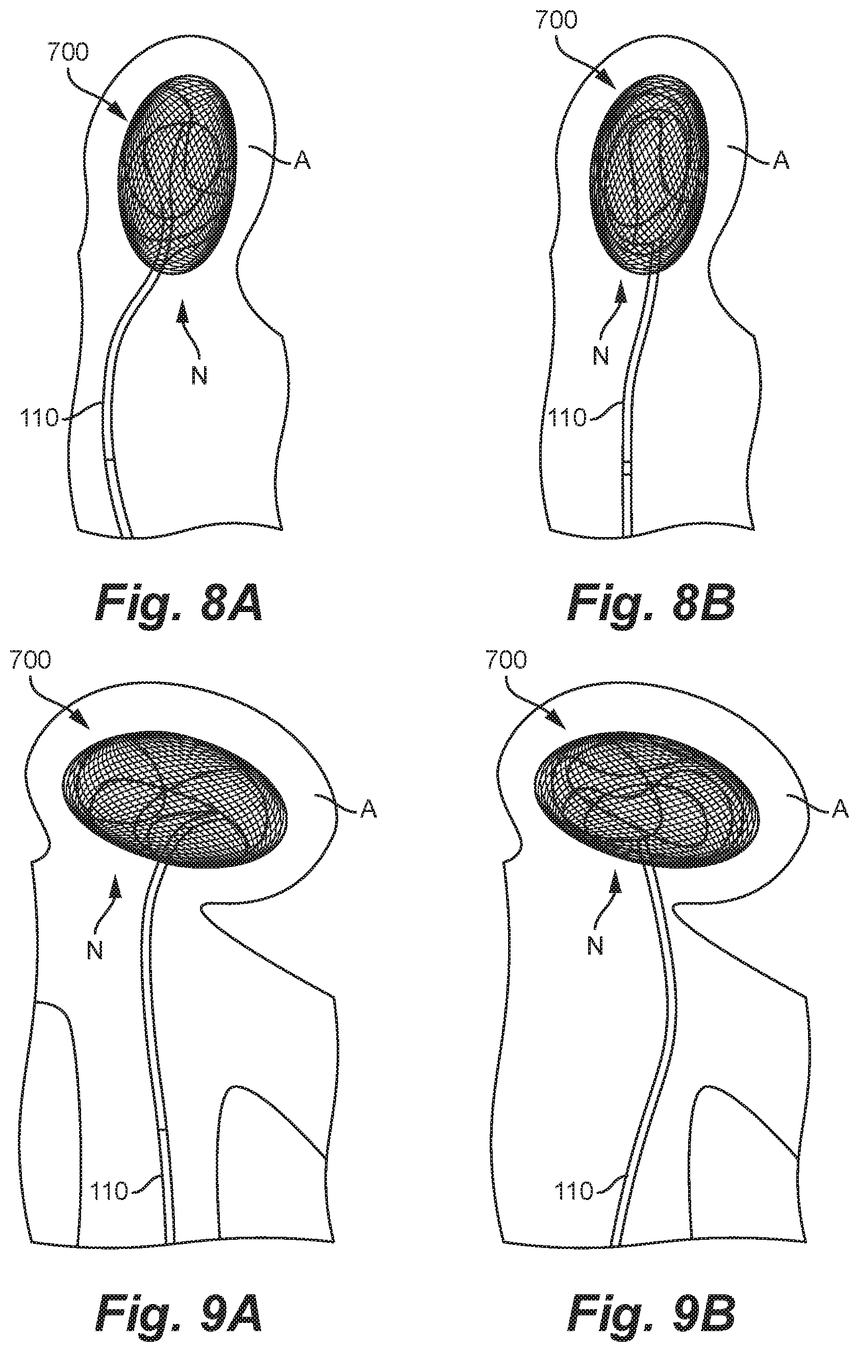
FIGS. 8A and 8B are fluoroscopic images showing a method of deploying an occlusion device within a wide aneurysm in accordance with some embodiments of the present technology.
FIGS. 9A and 9B are fluoroscopic images showing a method of deploying an occlusion device within a wide aneurysm in accordance with some embodiments of the present technology.
DETAILED DESCRIPTION
The detailed description set forth below is intended as a description of various configurations of the subject technology and is not intended to represent the only configurations in which the subject technology may be practiced. The appended drawings are incorporated herein and constitute a part of the detailed description. The detailed description includes specific details for the purpose of providing a thorough understanding of the subject technology. However, the subject technology may be practiced without these specific details.
FIG. 1A shows an occlusion device 100 in accordance with some embodiments of the present technology shown in an expanded, relaxed configuration outside of an aneurysm. FIG. 1F is a different view of the occlusion device 100 of FIG. 1A coupled to a delivery member 10. As shown in FIGS. 1A and 1F, the occlusion device 100 may comprise a mesh structure 102 having a low-profile state (not shown) for intravascular delivery to an aneurysm (e.g., a cerebral aneurysm) and an expanded state in which the mesh structure 102 is configured to be positioned within the interior cavity of the aneurysm. In the expanded state, the mesh structure 102 may include a plurality of interconnected, nested bands 122, 124, 126 that together define a predetermined three-dimensional shape, such as the spherical shape shown in FIG. 1A. Depending on the geometry of the aneurysm to be treated, the predetermined shape delimited by the bands 122, 124, 126 can be selected from a variety of spherical or non-spherical shapes, including cylinders, hemispheres, noodles, polyhedrons (e.g., cuboids, tetrahedrons (e.g. pyramids), octahedrons, prisms, etc.), prolate spheroids, oblate spheroids, plates (e.g., discs, polygonal plates), bowls, non-spherical surfaces of revolution (e.g., toruses, cones, cylinders, or other shapes rotated about a center point or a coplanar axis), and combinations thereof In FIG. 1A, the mesh structure 102 includes three bands (referred to as first, second, and third bands 122, 124, 126). In some embodiments, the mesh structure 102 can have more or fewer than three bands (e.g., two bands, four bands, five bands, six bands, etc.).
FIG. 1B is a top view of the occlusion device 100 after being unfurled from the deployed, relaxed configuration shown in FIG. 1A and held in an unfurled, elongated configuration to provide a better view of the entire length of the occlusion device 100. Referring to FIGS. 1A and 1B together, in some embodiments the mesh structure 102 can be formed of a single, continuous mesh ribbon 107 such that each of the bands 122, 124, 126 is formed of a different portion of the ribbon 107. In some embodiments, the bands 122, 124, 126 are formed of separate meshes and are joined end-to-end by one or more coupling elements. As best shown in FIG. 1B, the mesh ribbon 107 has a proximal end portion 102a, a distal end portion 102b, a longitudinal axis L extending between the proximal and distal end portions 102a, 102b, and side edges 110a and 110b extending longitudinally between the proximal and distal end portions 102a, 102b. In some embodiments, such as that shown in FIGS. 1A and 1B, the occlusion device 100 includes a proximal connector 104 and a distal connector 106 coupled to the proximal and distal end portions 102a, 102b, respectively, of the mesh ribbon 107. The proximal connector 104 may be configured to detachably couple the occlusion device 100 to a delivery system, and the distal connector 106 may be configured to couple a lead-in member to the mesh structure 102, as described in greater detail below with respect to FIGS. 2A-3B.
The mesh ribbon 107 can be formed of a tubular mesh that has been flattened along its longitudinal axis such that opposing portions of the sidewall are pressed against one another and/or into close proximity with one another. In some embodiments, the mesh ribbon 107 is formed of a flattened tubular braid. The braid may be formed of a plurality of wires, at least some of which (e.g., 25% of the wires, 50% of the wires, 80% of the wires, 100% of the wires, etc.) are made of one or more shape memory and/or superelastic materials (e.g., Nitinol). In some embodiments, at least some of the plurality of wires may be drawn-filled tubes ("DFT") having a have a radiopaque core (e.g., platinum) surrounded by a shape memory alloy and/or superelastic alloy (e.g., Nitinol). In these and other embodiments, at least a portion of the wires can be made of other suitable materials.
In some embodiments, the mesh ribbon 107 includes a plurality of band portions 142, 144, 146 positioned along its longitudinal axis L, and one or more bend portions 112 individually positioned between adjacent band portions 142, 144, 146 along the longitudinal axis L. The first, second, and third band portions 142, 144, 146 may be configured to form the first, second, and third bands 122, 124, 126, respectively, when the mesh structure 102 is in the expanded state. For example, as shown in FIGS. 1A and 1B, the mesh ribbon 107 may include a first band portion 142, a second band portion 144 distal of the first band portion 142 along the longitudinal axis L, and a third band portion 146 distal of the second band portion 144 along the longitudinal axis L. When the mesh structure 102 is in an expanded state, the first band portion 142 may curve around a first axis (coming out of the page) to form the first band 122, the second band portion 144 may curve around the second axis A2 to form the second band 124, and the third band portion 146 may curve around a third axis A3 to form the third band 126.
The occlusion device 100 is configured to be positioned in a compressed or low-profile state within a delivery catheter (e.g., a microcatheter) so that the distal end 102b of the mesh structure 102 is closest to the distal opening of the catheter and thus will be released from the delivery catheter first. Accordingly, the third band 126 deploys first from the delivery catheter, followed by the second band 124 and the first band 122. As a result, the second band 124 expands within an interior region defined by the already-expanded third band 126, and the first band 122 expands within an interior region defined by the already-expanded second band 124. Thus, when the mesh structure 102 is in an expanded configuration positioned within the aneurysm, the second band 124 is positioned radially inward of the third band 126, and the first band 122 is positioned radially inward of the second band 124. Even if one of the bands 122, 124, 126 is positioned radially inwardly of another of the bands 122, 124, 126 in the expanded configuration, when the mesh structure 102 is expanded within an aneurysm, any radially inward band may still contact and conform to the inner surface of the aneurysm along its non-overlapping regions, especially if the diameter of the mesh structure 102 in the expanded, relaxed state is greater than that of the aneurysm. In some embodiments, when the mesh structure 102 is in an expanded state, an outer surface of the second band 124 contacts an inner surface of the third band 126 at the corresponding overlapping regions, and an outer surface of the first band 122 contacts an inner surface of the second band 124 at the corresponding overlapping regions.
Because the bands 122, 124, 126 are oriented along different planes, the bands 122, 124, 126 overlap one another along their respective circumferences, thereby forming a plurality of overlapping regions in which the porosity of the mesh structure 102 is less than it is at the non-overlapping regions of the mesh structure 102. For example, as shown in FIG. 1A, the mesh structure 102 may include six overlapping regions (e.g., 132, 134, 136, 138, 140, and 142). Depending on the number of the bands and width of the bands, the mesh structure 102 may include more or fewer overlapping regions (e.g., two overlapping regions, eight overlapping regions, etc.). The occlusion device 100 may be configured to be positioned within the aneurysm so that at least one of the overlapping regions is positioned over all or a portion of the neck of the aneurysm, thereby preventing egress of the device 100 into the parent vessel, and also disrupting the flow of blood into the aneurysm. Even if a single overlapping region covers only a portion of the aneurysm neck, the portions of the bands adjacent that overlapping region collectively provide complete or near complete neck coverage.
In some embodiments, for example as shown in FIG. 1A, when the device 100 is in the expanded state, the side edges 110a, 110b of each of the bands are spaced apart from the side edges of the other bands along at least a portion of their circumferential lengths such that the device includes openings 130 at its outer surface. In some embodiments, when the device 100 is in the expanded state, the device 100 may be configured such that the side edges 110a, 110b contact one another along at least a portion of their circumferential lengths and/or overlap one another along at least a portion of their circumferential lengths such that the bands together define a continuous outer surface of the three-dimensional shape formed by the bands (such as a sphere).
Each of the bands 122, 124, 126 may be a closed band (e.g., circumscribes a closed shape) (shown schematically in FIGS. 1C and 1D) or an open band (e.g., circumscribes an open shape) (shown schematically in FIG. 1E). For example, as shown in FIG. 1C, in some embodiments the third band portion 146 may curve 360 degrees around the third axis A3 (coming out of the page in FIG. 1C) such that the proximal end 146a of the third band portion 146 comes back around and meets the distal end 146b of the third band portion 146, thereby closing the loop and forming a closed band. As illustrated by FIG. 1D, in some embodiments the third band portion 146 may wrap around the third axis A3 more than 360 degrees such that it overlaps itself (i.e., the proximal end 146a extends circumferentially beyond the distal end 146b) along at least a portion of the circumference of the band 126, thereby forming a closed band. As illustrated by FIG. 1E, in some embodiments the third band portion 146 may curve around the third axis A3 less than 360 degrees (e.g., 330 degrees, 300 degrees, 280 degrees, 260 degrees, 230 degrees, 180 degrees, etc.) such that the proximal end 146a of the third band portion 146 does not meet the distal end 146b, thereby forming an open band. The foregoing description of the "closed" and "open" configurations of the third band 126/third band portion 146 also applies to the "closed" and "open" configurations of the first band 122/first band portion 142 and the second band 124/second band portion 144. In some embodiments, all of the bands 122, 124, 126 may be closed bands, and in some embodiments all of the bands 122, 124, 126 may be open bands. In some embodiments, at least one of the bands 122, 124, 126 is an open band and at least one of the bands 122, 124, 126 is a closed band. In some embodiments, it may be beneficial to include at least one open band as such a configuration decreases the overall length of the mesh ribbon 107 (thus making the occlusion device 100 easier to deliver through a catheter to the aneurysm) and/or frees up some of the length of the mesh ribbon 107 that can instead be used for additional bands or turns of the mesh.
The bands 122, 124, 126/band portions 142, 144, 146 can have the same or different widths w (i.e., distance between the side edges 110a, 110b) as the other bands/band portions. As shown in FIGS. 1A and 1B, each of the bands 122, 124, 126 may have tapered proximal and distal ends and a generally constant width therebetween. In some embodiments, the bands/band portions do not have any tapered regions and maintain a generally constant width along their entire respective lengths. In some embodiments, one or more of the bands/band portions have a width w that varies along its respective length.
As shown in FIGS. 1A and 1B, adjacent bands/band portions may be coupled to one another via the bend portions. In those embodiments where the bands 122, 124, 126 are formed of a single mesh ribbon, the bend portions can be narrowed regions of the mesh ribbon 107 that have been heat set to form a predetermined bend when the mesh structure 102 is in the expanded state. For example, in some embodiments the first band 122/first band portion 142 may be coupled to the second band 124/second band portion 144 by a proximal narrowed region 123, and the second band 124/second band portion 144 may be coupled to the third band 126/third band portion 146 by a distal narrowed region 125. At least when the mesh structure 102 is in the expanded, relaxed state, each of the narrowed regions 123, 125 can have a width that is less than a width w of each of the band/band portions. In those embodiments where the bands/band portions are formed of separate, discrete mesh ribbons, the bend portions can comprise separate coupling elements that link the ends of adjacent bands/band portions (such as the articulation joints shown in FIGS. 4B and 7B).
Referring to FIG. 1A, when the mesh structure 102 is in an expanded state, each of the bands 122, 124, 126 may be centered about a different axis. For example, the narrowed regions 123 and 125 are heat set to form a predetermined bend in the mesh ribbon 107 in the expanded configuration that positions the bands 122, 124, 126 at a predetermined angle relative to one another. In some embodiments, such as that shown in FIG. 1A, the individual axes of the bands 122, 124, 126 may be perpendicular to one another.
In some embodiments the occlusion device 100 may optionally include a soft, curved lead-in member 108 coupled to the distal end portion 102b of the mesh structure 102 via the distal connector 106. The lead-in member 108 may have a curved shape in a deployed configuration. For example, the lead-in member 108 initially extends distally with respect to the mesh structure 102 (e.g., from the distal connector 106) then curves proximally. Because the lead-in member 108 is the first portion of the occlusion device 100 that exits the delivery catheter and contacts the aneurysm wall, the soft material and/or curved shape of the lead-in member 108 reduces or eliminates stress on the aneurysm wall when delivering the occlusion device 100 to the aneurysm sac. In some embodiments the lead-in member 108 can be generally straight and/or have other atraumatic yet sufficiently resilient configurations. In some embodiments, the lead-in member 108 is a curled mesh (e.g., a braid) that is coupled to the distal connector 106. The curled mesh can be integral with the mesh that forms the mesh structure 102, or the curled mesh can be a separate mesh. In some embodiments, the lead-in member 108 is a separate, coiled tube (e.g., a radiopaque coil) that is coupled to the distal connector 106. In some embodiments, the lead-in member 108 can be formed integrally or monolithically with the occlusion device 100. In yet other embodiments, the occlusion device 100 does not include a lead-in member 108 and the distal portion of the occlusion device 100 is comprised solely of the distal connector 106 and/or distal end portion 102b of the mesh structure 102.
In some embodiments, the stiffness of the mesh structure 102 and/or occlusion device 100 is generally constant along its longitudinal axis L. In some embodiments, the stiffness of the mesh structure 102 and/or occlusion device 100 varies along its longitudinal axis L. For example, the stiffness of one or more portions of the mesh ribbon 107 and/or mesh structure 102 can be different than other portions of the mesh ribbon 107 and/or mesh structure 102 by varying one or more parameters such as the materials, porosity, thickness, braid count (if applicable), and braid pitch (if applicable) in the individual portions. For example, for the mesh ribbon 107 shown in FIGS. 1A and 1B, it may be desirable for the more distal first band portion 146 comprising the outermost portion of the mesh structure 102 to have a first stiffness for framing the aneurysm, and the more proximal first and second band portions 142, 144 comprising the inner mesh structures to have a second stiffness less than the first stiffness so that the first and second bands 124, 122 are more flexible than the larger third band 126 for packing the aneurysm. Moreover, it may be desirable for the third band portion 146 to be relatively stiffer than the more proximal first and second band portions 142, 144 since, once the occlusion device 100 is positioned within the aneurysm, the stiffness will enhance the anchoring and structural integrity of the first band 146.
To enhance visibility of the occlusion device 100 and/or mesh structure 102 during delivery to the aneurysm and/or subsequent to implantation within the aneurysm, the occlusion device 100 may optionally include a flexible member (not shown), such as a radiopaque element (e.g., a platinum coil), that extends along and/or within at least a portion of the length of the mesh structure 102. The proximal and distal ends of the flexible member are coupled to the proximal and distal end portions 102a, 102b, respectively, of the mesh structure 102 and/or the proximal and distal connectors 104, 106, respectively (e.g., directly or via a suture). In other embodiments, only one end of the flexible member is connected to one of the proximal connector 104 or the distal connector 106.
2.0 Methods of Use
In use, the occlusion device 100 is intravascularly delivered to a location within a blood vessel lumen L adjacent a target aneurysm A in a low-profile configuration (not shown) within a delivery catheter 10. The distal portion of the delivery catheter 10 is then advanced through the neck N of the aneurysm A to an interior region of the aneurysm A. As shown in FIG. 2A, the occlusion device 100 is then deployed by pushing the occlusion device 100 distally through the distal opening of the delivery catheter 10 towards the inner wall of the aneurysm A. The third band portion 146 exits the delivery catheter 10 first and, as it's deployed, the third band portion 146 curves around the curved inner surface of the aneurysm A until forming the third band 126. The distal narrowed region 125 deploys next and assumes a first predetermined bend that directs the following second band portion 144 to curve around the aneurysm wall about an axis that is perpendicular to the central axis of the third band 126, thereby forming the second band 124. The proximal narrowed region 123 deploys next and assumes a second predetermined bend that directs the following first band portion 142 to curve around the aneurysm wall about an axis that is perpendicular to a central axis of the third band 126 and a central axis of the second band 124, thereby forming the first band 122. As shown in FIG. 2B, at least one of the overlapping regions is positioned over all or a portion of the neck N, thereby preventing egress of the device 100 into the parent vessel, and also disrupting the flow of blood into the aneurysm A. Unlike conventional devices, the occlusion device 100 is configured to treat a range of aneurysm geometries without additional anchoring devices. For example, FIGS. 2A and 2B show the occlusion device 100 anchored within and conformed to a tall aneurysm geometry (aspect ratio.ltoreq.1:2), and FIGS. 3A and 3B show the occlusion device 100 anchored within and conformed to a wide aneurysm geometry (aspect ratio.gtoreq.2:1).
3.0 Additional Embodiments
FIGS. 4A-9B show several embodiments of occlusion devices configured in accordance with the present technology. For example, FIG. 4A illustrates an occlusion device 400 (or "device 400") comprising a mesh structure 401 having an expanded, relaxed state in which it includes a globular (e.g., cylindrical, spherical, ball-shaped, barrel-shaped, etc.) first portion 404 and a helical second portion 402. In some embodiments, such as that shown in FIG. 4A, the first and second portions 404, 402 can be separate meshes coupled via a coupling element 406. In some embodiments, the first and second portions 404, 402 can be formed from a single, continuous mesh such that the first and second portions 404, 402 are integrally connected with one another. In some embodiments, one or both of the first and second portions 404, 402 are formed of a braided material.
The globular first portion 404 can have a proximal connector 405 at its proximal end and a distal connector 412 at its distal end. The proximal connector 405 is configured to detachably couple the occlusion device 400 to a delivery device (such as delivery member 110). As such, the helical second portion 402 is configured to be delivered first to the aneurysm, followed by the first portion 404. The distal connector 412 may include a loop 416 extending therefrom and configured to engage and/or interlock with a loop 414 extending from a proximal connector 410 at a proximal end of the second portion 402. The interlocking loops 414, 416 allow the second portion 402 to bend and rotate (to some extent) relative to the first portion 404 (and vice versa), thus enabling the device 400 to adapt to the shape and size of the aneurysm.
The helical second portion 402 can be formed of a mesh ribbon 407 wrapped about an axis a plurality of times to form a plurality of mesh turns 403 (only two labeled for ease of illustration) in the expanded configuration. The mesh turns 403 may overlap one another along their edges. The mesh ribbon 407 can be formed of a tubular mesh (e.g., a braided tube) that has been flattened along its longitudinal axis such that opposing portions of the sidewall are pressed against one another and/or into close proximity with one another. In some embodiments, the mesh ribbon 407 is formed of a flattened tubular braid. The braid may be formed of a plurality of wires, at least some of which (e.g., 25% of the wires, 50% of the wires, 80% of the wires, 100% of the wires, etc.) are made of one or more shape memory and/or superelastic materials (e.g., Nitinol). In some embodiments, at least some of the plurality of wires may be drawn-filled tubes ("DFT") having a have a radiopaque core (e.g., platinum) surrounded by a shape memory alloy and/or superelastic alloy (e.g., Nitinol). In these and other embodiments, at least a portion of the wires can be made of other suitable materials.
FIGS. 5A and 5B are fluoroscopic images the occlusion device 400 being deployed within a wide aneurysm in accordance with some embodiments of the present technology, and FIGS. 6A and 6B are fluoroscopic images showing the occlusion device 400 being deployed within a tall aneurysm in accordance with some embodiments of the present technology. As shown, the helical second portion 402 may be deployed first within the aneurysm, followed by the first portion 404. The globular first portion 404 can press outwardly against the aneurysm wall and help anchor the first portion 402 within the aneurysm. The globular first portion 404 can also fill any gaps at the neck of the aneurysm left by the second portion 402.
FIG. 7A illustrates an occlusion device 700 (or "device 700") comprising a mesh structure 701 having an expanded, relaxed state in which it includes a globular (e.g., cylindrical, spherical, ball-shaped, barrel-shaped, etc.) first portion 704 and a second portion 702. In some embodiments, such as that shown in FIG. 4A, the first and second portions 704, 702 can be separate meshes coupled via a coupling element 406. In some embodiments, the first and second portions 704, 702 can be formed from a single, continuous mesh such that the first and second portions 704, 702 are integrally connected with one another. In some embodiments, one or both of the first and second portions 704, 702 are formed of a braided material.
The globular first portion 704 can have a proximal connector 405 at its proximal end and a distal connector 412 at its distal end. The proximal connector 405 is configured to detachably couple the occlusion device 700 to a delivery device (such as delivery member 110). The distal connector 412 may include a loop 416 extending therefrom and configured to engage and/or interlock with a loop 414 extending from a proximal connector 410 at a proximal end of the second portion 702. The interlocking loops 414, 416 allow the second portion 702 to bend and rotate (to some extent) relative to the first portion 404 (and vice versa), thus enabling the device 700 to adapt to the aneurysm cavity.
The second portion 702 can include a plurality of rectangular regions 703 separated by flexible, narrowed bend regions 709. The second portion 702 may be formed of a mesh ribbon 707. The mesh ribbon 707 can be formed of a tubular mesh (e.g., a braided tube) that has been flattened along its longitudinal axis such that opposing portions of the sidewall are pressed against one another and/or into close proximity with one another. In some embodiments, the mesh ribbon 707 is formed of a flattened tubular braid. The braid may be formed of a plurality of wires, at least some of which (e.g., 25% of the wires, 50% of the wires, 80% of the wires, 100% of the wires, etc.) are made of one or more shape memory and/or superelastic materials (e.g., Nitinol). In some embodiments, at least some of the plurality of wires may be drawn-filled tubes ("DFT") having a have a radiopaque core (e.g., platinum) surrounded by a shape memory alloy and/or superelastic alloy (e.g., Nitinol). In these and other embodiments, at least a portion of the wires can be made of other suitable materials.
FIGS. 8A and 8B are fluoroscopic images showing the occlusion device 700 being deployed within a tall aneurysm in accordance with some embodiments of the present technology, and FIGS. 9A and 9B are fluoroscopic images showing the occlusion device 700 being deployed within a wide aneurysm in accordance with some embodiments of the present technology. As shown, the second portion 702 may be deployed first within the aneurysm, followed by the first portion 704. The globular first portion 704 can press outwardly against the aneurysm wall and help anchor the first portion 702 within the aneurysm. The globular first portion 704 can also fill any gaps at the neck of the aneurysm left by the second portion 702.
5.0 Conclusion
Although many of the embodiments are described above with respect to devices, systems, and methods for treating a cerebral aneurysm, other applications and other embodiments in addition to those described herein are within the scope of the technology. For example, the occlusion devices, systems, and methods of the present technology can be used to treat any vascular defect and/or fill or partially fill any body cavity or lumen or walls thereof. Additionally, several other embodiments of the technology can have different states, components, or procedures than those described herein. It will be appreciated that specific elements, substructures, advantages, uses, and/or other features of the embodiments described can be suitably interchanged, substituted or otherwise configured with one another in accordance with additional embodiments of the present technology. A person of ordinary skill in the art, therefore, will accordingly understand that the technology can have other embodiments with additional elements, or the technology can have other embodiments without several of the features shown and described above.
* * * * *
D00000
D00001
D00002
D00003
D00004
D00005
D00006
D00007
XML
uspto.report is an independent third-party trademark research tool that is not affiliated, endorsed, or sponsored by the United States Patent and Trademark Office (USPTO) or any other governmental organization. The information provided by uspto.report is based on publicly available data at the time of writing and is intended for informational purposes only.
While we strive to provide accurate and up-to-date information, we do not guarantee the accuracy, completeness, reliability, or suitability of the information displayed on this site. The use of this site is at your own risk. Any reliance you place on such information is therefore strictly at your own risk.
All official trademark data, including owner information, should be verified by visiting the official USPTO website at www.uspto.gov. This site is not intended to replace professional legal advice and should not be used as a substitute for consulting with a legal professional who is knowledgeable about trademark law.