Torque converter clutch assembly for hybrid module
Adams , et al. April 12, 2
U.S. patent number 11,303,192 [Application Number 17/088,020] was granted by the patent office on 2022-04-12 for torque converter clutch assembly for hybrid module. This patent grant is currently assigned to Schaeffler Technologies AG & Co. KG. The grantee listed for this patent is Schaeffler Technologies AG & Co. KG. Invention is credited to Jonathan Adams, Kyle Nelson, Victor Norwich.


| United States Patent | 11,303,192 |
| Adams , et al. | April 12, 2022 |
Torque converter clutch assembly for hybrid module
Abstract
A torque converter comprises a front cover, an impeller having an impeller shell fixed to the front cover, and a turbine fluidly coupled with the impeller and having a turbine shell. A damper assembly is provided that includes an output flange connected to the turbine shell. A clutch assembly is disposed between the front cover and the turbine. The clutch assembly comprises a piston sealed to the front cover at an outer diameter thereof and a clutch flow deflector plate disposed axially between the piston and the output flange, wherein the clutch flow deflector plate is configured to direct a cooling fluid to the clutch assembly.
| Inventors: | Adams; Jonathan (Pittsburgh, OH), Nelson; Kyle (Wadsworth, OH), Norwich; Victor (Wooster, OH) | ||||||||||
|---|---|---|---|---|---|---|---|---|---|---|---|
| Applicant: |
|
||||||||||
| Assignee: | Schaeffler Technologies AG &
Co. KG (Herzogenaurach, DE) |
||||||||||
| Family ID: | 1000006236617 | ||||||||||
| Appl. No.: | 17/088,020 | ||||||||||
| Filed: | November 3, 2020 |
Prior Publication Data
| Document Identifier | Publication Date | |
|---|---|---|
| US 20210140525 A1 | May 13, 2021 | |
Related U.S. Patent Documents
| Application Number | Filing Date | Patent Number | Issue Date | ||
|---|---|---|---|---|---|
| 62933364 | Nov 8, 2019 | ||||
| Current U.S. Class: | 1/1 |
| Current CPC Class: | H02K 11/21 (20160101); F16H 45/02 (20130101); H02K 24/00 (20130101); B60K 1/00 (20130101); B60K 6/26 (20130101); B60Y 2200/92 (20130101); B60K 2006/264 (20130101); F16H 2045/0221 (20130101) |
| Current International Class: | F16H 45/02 (20060101); B60K 6/26 (20071001); B60K 1/00 (20060101); H02K 11/21 (20160101); H02K 24/00 (20060101) |
References Cited [Referenced By]
U.S. Patent Documents
| 2007/0235277 | October 2007 | Heuler |
| 2013/0111891 | May 2013 | Iwase |
| 2019/0178356 | June 2019 | Vanni |
| 2020/0039496 | February 2020 | Lindemann et al. |
Claims
What is claimed is:
1. A torque converter, comprising: a front cover; an impeller having an impeller shell fixed to the front cover; a turbine fluidly coupled with the impeller and having a turbine shell; a damper assembly including an output flange connected to the turbine shell; a clutch assembly disposed between the front cover and the turbine, the clutch assembly comprising: a piston sealed to the front cover at an outer diameter thereof; and a clutch flow deflector plate disposed axially between the piston and the output flange, wherein the clutch flow deflector plate is configured to direct a cooling fluid to the clutch assembly; and a thrust washer connected to the output flange, wherein the clutch flow deflector plate includes an outer portion contacting the piston on a first axial side and an inner portion contacting the thrust washer on a second, opposite axial side.
2. The torque converter of claim 1, wherein the piston is arranged to seal to a transmission input shaft at an inner diameter and an apply chamber is formed between the front cover and the piston for supplying pressurized fluid to engage the clutch assembly.
3. The torque converter of claim 1, wherein a first fluid chamber is formed, at least in part, by the piston, the clutch flow deflector plate, and the output flange and a second fluid chamber is formed, at least in part, by the output flange and a stator.
4. The torque converter of claim 3, wherein the output flange includes an opening extending axially therethrough and a cooling fluid is supplied to the first fluid chamber from the second fluid chamber via the opening.
5. The torque converter of claim 4, wherein the cooling fluid is directed from the first fluid chamber to the clutch assembly via a groove defined in the piston.
6. The torque converter of claim 4, wherein the opening in the output flange is located radially inward of the thrust washer.
7. The torque converter of claim 1, wherein: the damper assembly includes a first cover plate and a second cover plate supporting a spring therebetween; and the clutch assembly includes an inner clutch plate connected to the first cover plate or the second cover plate.
8. The torque converter of claim 7, wherein the first cover plate or the second cover plate includes an axially extending tab and the inner clutch plate is connected to the axially extending tab.
9. A hybrid module comprising: a torque converter comprising: a front cover; an impeller having an impeller shell fixed to the front cover; a turbine fluidly coupled with the impeller and having a turbine shell; a damper assembly including an output flange connected to the turbine shell; and a clutch assembly disposed between the front cover and the turbine, the clutch assembly including: a piston sealed to the front cover at an outer diameter thereof; and a clutch flow deflector plate disposed axially between the piston and the output flange, wherein the clutch flow deflector plate is configured to direct a cooling fluid to the clutch assembly, an e-motor assembly including a rotor mounted on an outer surface of the front cover; and a resolver attached to an impeller hub, wherein the impeller hub is attached to the impeller shell and extends axially therefrom.
10. A torque converter, comprising: a front cover; an impeller having an impeller shell fixed to the front cover; a turbine fluidly coupled with the impeller and having a turbine shell; a damper assembly including an output flange connected to the turbine shell and arranged for sealing with a transmission input shaft; and a clutch assembly comprising: a piston configured to be axially displaced for engagement of the clutch assembly; a reaction plate fixed to the front cover; and a clutch flow deflector plate connected to the reaction plate and disposed axially between the piston and the output flange, wherein a chamber is formed, at least in part, by the piston, the clutch flow deflector plate, and the output flange for supplying a cooling fluid to the clutch assembly, wherein the cooling fluid is supplied from the chamber into the clutch assembly via an axially extending groove defined in the piston and through a tooth interface provided between the clutch flow deflector plate and the reaction plate.
11. The torque converter of claim 10, wherein the clutch flow deflector plate is attached to the output flange at an inner end and contacts the piston at an outer end.
12. The torque converter of claim 11, wherein the clutch flow deflector plate is attached to the output flange by a thrust washer.
13. The torque converter of claim 11, wherein an apply chamber is formed between the front cover and the piston and is arranged to receive a pressurized fluid for engagement of the clutch assembly.
14. The torque converter of claim 10, wherein the piston is sealed to the front cover at an outer diameter thereof and arranged for sealing with the transmission input shaft at an inner diameter.
Description
TECHNICAL FIELD
The present disclosure relates generally to a hybrid module, and more specifically to a torque converter clutch assembly for a hybrid module.
BACKGROUND
Hybrid modules are generally known. Often, it is a challenge to package and/or fit all the desired components, e.g., an e-motor, crank damper, torque converter, torque converter clutch, disconnect clutch, and resolver within the hybrid module architecture due to axial constraints. For example, the available surface area of the torque converter clutch assembly may be limited due to these axial constraints thereby impacting clutch cooling capacity, performance, and energy dissipation.
SUMMARY
Embodiments disclose a torque converter comprising a front cover, an impeller having an impeller shell fixed to the front cover, and a turbine fluidly coupled with the impeller and having a turbine shell. A damper assembly is provided that includes an output flange connected to the turbine shell. A clutch assembly is disposed between the front cover and the turbine. The clutch assembly comprises a piston sealed to the front cover at an outer diameter thereof and a clutch flow deflector plate disposed axially between the piston and the output flange, wherein the clutch flow deflector plate is configured to direct a cooling fluid to the clutch assembly.
In embodiments, the piston is arranged to seal to a transmission input shaft at an inner diameter and an apply chamber is formed between the front cover and the piston for supplying pressurized fluid to engage the clutch assembly. A thrust washer may be connected to the output flange, wherein the clutch flow deflector plate includes an outer portion contacting the piston on a first axial side and an inner portion contacting the thrust washer on a second, opposite axial side. Moreover, a first fluid chamber is formed, at least in part, by the piston, the clutch flow deflector plate, and the output flange and a second fluid chamber is formed, at least in part, by the output flange and a stator of the torque converter. The output flange may include an opening extending axially therethrough and a cooling fluid is supplied to the first chamber from the second chamber via the opening. The cooling fluid is directed from the first chamber to the clutch assembly via a groove defined in the piston. Additionally, the opening in the output flange is located radially inward of the thrust washer.
In other embodiments, the damper assembly includes a first cover plate and a second cover plate supporting a spring therebetween; and the clutch assembly includes an inner clutch plate connected to the first cover plate or the second cover plate. The first cover plate or the second cover plate may include an axially extending tab and the inner clutch plate may be drivingly connected to the axially extending tab. A hybrid module may include the torque converter disclosed herein with an e-motor assembly including a rotor mounted on an outer surface of the front cover and a resolver attached to an impeller hub, wherein the impeller hub is attached to the impeller shell and extends axially therefrom.
In embodiments, a torque converter comprises a front cover, an impeller having an impeller shell fixed to the front cover, and a turbine fluidly coupled with the impeller and having a turbine shell. A damper assembly is provided that includes an output flange connected to the turbine shell and arranged for sealing with a transmission input shaft. A clutch assembly is provided that includes: a piston configured to be axially displaced for engagement of the clutch assembly; a reaction plate fixed to the front cover; and a clutch flow deflector plate connected to the reaction plate and disposed axially between the piston and the output flange, wherein a chamber is formed, at least in part, by the piston, the clutch flow deflector plate, and the output flange for supplying a cooling fluid to the clutch assembly.
In embodiments, the clutch flow deflector plate may be attached to the output flange at an inner end and contact the piston at an outer end. The clutch flow deflector plate may further be attached to the output flange by a thrust washer. The cooling fluid may be supplied from the chamber into the clutch assembly via an axially extending groove defined in the piston and through a tooth interface provided between the clutch flow deflector plate and the reaction plate. The piston may be sealed to the front cover at an outer diameter thereof and arranged for sealing with the transmission input shaft at an inner diameter. An apply chamber may be formed between the front cover and the piston and may be arranged to receive a pressurized fluid for engagement of the clutch assembly.
BRIEF DESCRIPTION OF THE DRAWINGS
FIG. 1 shows a cross-sectional view of a hybrid module according to an embodiment of the present disclosure.
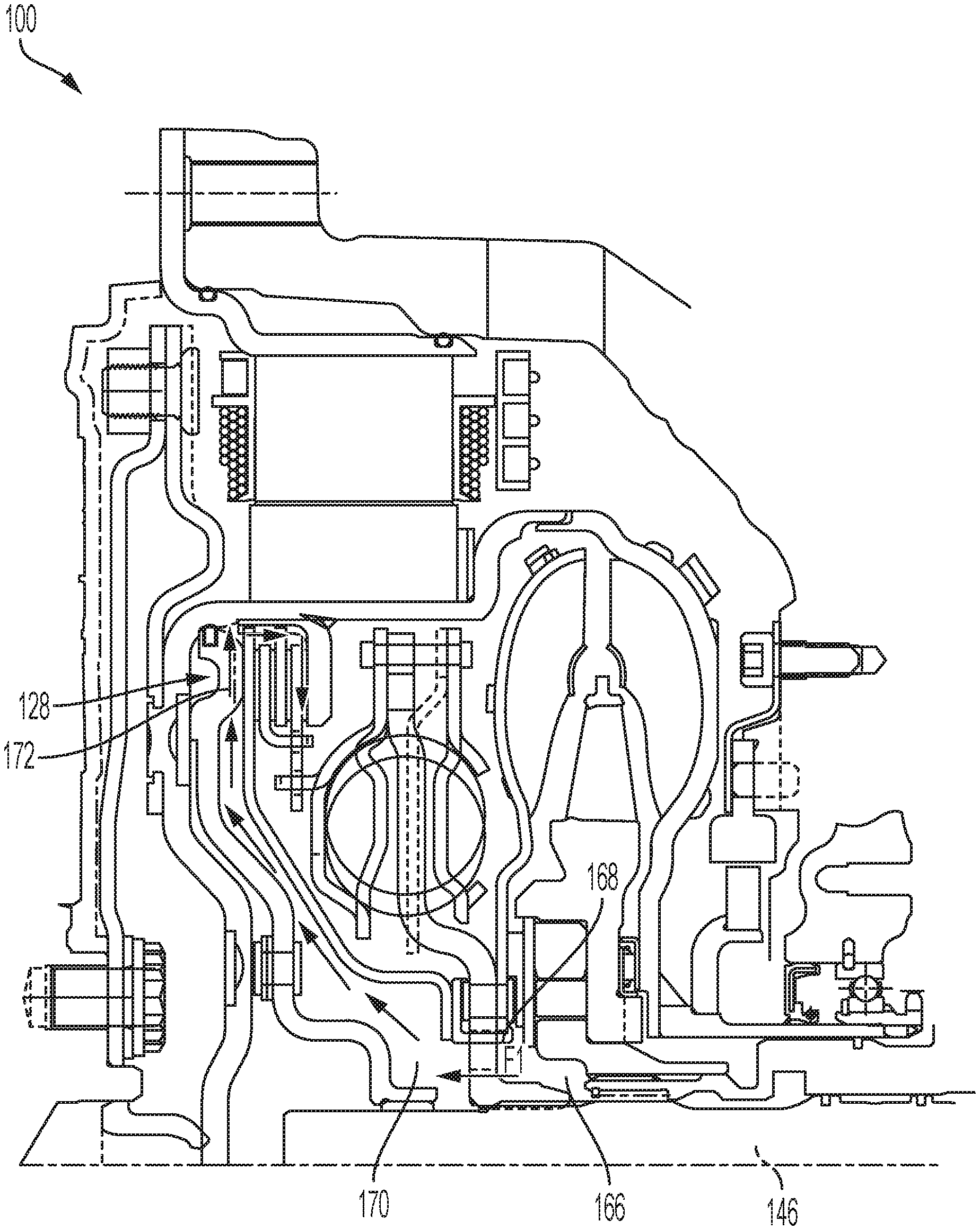
FIG. 2 shows a torque converter clutch cooling flow for the hybrid module shown in FIG. 1.
DETAILED DESCRIPTION
Embodiments of the present disclosure are described herein. It should be appreciated that like drawing numbers appearing in different drawing views identify identical, or functionally similar, structural elements. Also, it is to be understood that the disclosed embodiments are merely examples and other embodiments can take various and alternative forms. The figures are not necessarily to scale; some features could be exaggerated or minimized to show details of particular components. Therefore, specific structural and functional details disclosed herein are not to be interpreted as limiting, but merely as a representative basis for teaching one skilled in the art to variously employ the embodiments. As those of ordinary skill in the art will understand, various features illustrated and described with reference to any one of the figures can be combined with features illustrated in one or more other figures to produce embodiments that are not explicitly illustrated or described. The combinations of features illustrated provide representative embodiments for typical applications. Various combinations and modifications of the features consistent with the teachings of this disclosure, however, could be desired for particular applications or implementations.
The terminology used herein is for the purpose of describing particular aspects only and is not intended to limit the scope of the present disclosure. Unless defined otherwise, all technical and scientific terms used herein have the same meaning as commonly understood to one of ordinary skill in the art to which this disclosure belongs. Although any methods, devices or materials similar or equivalent to those described herein can be used in the practice or testing of the disclosure, the following example methods, devices, and materials are now described.
Due to axial constraints and reduced envelope sizes for hybrid modules, the available surface area of the multi-plate torque converter clutch assembly may be limited, which impacts clutch cooling capacity, performance, and energy dissipation in operating conditions, such as slip conditions. It is thereby an object of the present disclosure to provide embodiments herein that reduce the loss of flow to the clutch and increases clutch performance and cooling capacity without the use or added costs of additional dynamic seals. In particular, embodiments disclosed herein provide for the torque converter clutch plate to act as a flow guide to route or direct cooling fluid flow from the transmission input shaft to the clutch assembly before reaching the torus of the torque converter.
FIG. 1 shows a cross-sectional view of hybrid module 100 according to an embodiment of the present disclosure. FIG. 2 shows a torque converter clutch cooling flow for hybrid module 100. The following description is made in view of FIGS. 1-2. Hybrid module 100 includes torque converter 102 and e-motor assembly 104. Torque converter 102 includes: impeller assembly 108 having a plurality of blades 110 attached to impeller shell 112; turbine assembly 114 having a plurality of blades 116 attached to turbine shell 118; and stator assembly 120 having blades 122 supported by stator body 124. Impeller shell 112 may be connected or fixed to front cover 126, for example, via a welded connection. Impeller shell 112 and front cover 126 may form the housing or enclosure of torque converter 102.
Torque converter 102 further includes clutch assembly 128 and damper assembly 130. Clutch assembly 128 may include: piston 132; clutch flow deflector plate 134; inner clutch plate 136; inner clutch plate 138; outer clutch plate 140; and reaction plate 142. Piston 132 is disposed axially between clutch flow deflector plate 134 and front cover 126. Piston 132 may be sealed at an outer diameter thereof to front cover 126 via seal 144 and arranged to be sealed to a transmission input shaft 146 by bushing 148 at an inner diameter thereof, for example. Piston 132 may further be non-rotatably connected to front cover 126 by leaf springs 150. An apply chamber 152 is thereby formed between front cover 126, piston 132, and seal 144 and arranged to receive pressurized fluid for lock-up or engagement of clutch assembly 128 to transfer torque therebetween. Inner clutch plates 136, 138 may be connected to each other at an inner diameter, for example, by a tabbed connection. Clutch flow deflector plate 134 and outer clutch plate 140 may be connected to reaction plate 142 at outer diameters thereof, for example, via a tooth interface. Reaction plate 142 may be fixed to front cover 126, for example via welding. Clutch flow deflector plate 134, inner clutch plate 136, inner clutch plate 138, and outer clutch plate 140 may be disposed axially between piston 132 and reaction plate 142. That is, pressurized fluid may be supplied to apply chamber 152 from transmission input shaft 146 to axially displace piston 132 to compress clutch flow deflector plate 134, inner clutch plate 136, inner clutch plate 138, and outer clutch plate 140 against reaction plate 142 to engage clutch assembly 128.
Damper assembly 130 includes: first cover input plate 154; second cover input plate 156; springs 158 supported between first and second cover plates 154, 156; and output flange 160. First cover input plate 154 may be drivingly engaged with inner clutch plates 136, 138, for example, by axially extending tab 162. Output flange 160 may be connected to turbine shell 118 and arranged to be fixed to transmission input shaft 146. Thrust washer 164 may be attached to output flange 160 on an axial side facing front cover 126. Clutch flow deflector plate 134 may be disposed axially between piston 132 and output flange 160 such that a first axial side contacts piston 132 at an outer end and a second, opposite axial side contacts thrust washer 164 at an inner end.
Clutch flow deflector plate 134 is configured and arranged to direct or route cooling fluid F1 from transmission input shaft 146 to and around clutch assembly 128 (see FIG. 2, for example). That is, cooling fluid F1 is supplied from transmission input shaft 146 to chamber 166 formed between stator assembly 120 and output flange 160. From chamber 166, cooling fluid F1 is routed through holes or openings 168 defined in output flange 160 into chamber 170 formed between clutch flow deflector plate 134, piston 132, and output flange 160. Cooling fluid F1 is then routed through chamber 170 to clutch assembly 128 via flow path 172 defined in piston 132. Flow path 172 may extend axially within piston 132 and may be formed as a groove that is machined or stamped, for example. That is, cooling fluid F1 flows up through flow path 172 in piston 132 and then through the tooth interface provided between reaction plate 142 and clutch flow deflector plate 134 and outer clutch plate 138. Some of the teeth in this tooth interface may be purposefully removed for targeted cooling flow therethrough. Cooling fluid F1 is then dispersed through clutch facings or surfaces of clutch flow deflector plate 134, inner clutch plate 136, inner clutch plate 138, and outer clutch plate 140. Cooling fluid F1 exits the inner diameter of the clutch facings or surfaces of clutch flow deflector plate 134, inner clutch plate 136, inner clutch plate 138, and outer clutch plate 140, which may be grooved surfaces to facilitate fluid flow therethrough.
Hybrid module 100 further includes resolver assembly 174 attached to impeller hub 176 of torque converter 102 via rotor mounting ring 178. Impeller hub 176 is connected to impeller shell 112, for example, via a welded connection and extends axially therefrom. Rotor mounting ring 178 is fixed to an outer surface of impeller hub 176, for example, via a press-fit connection. Resolver assembly 174 further includes rotor 180 and stator 182. Rotor 180 is fixed to rotor mounting ring 178, for example, via a press-fit connection. Stator 182 is fixed to transmission housing 184 via plate 186 and connector 188, for example, a bolt. That is, connector 188 fixes plate 186 to transmission housing 184 and stator 182 is clamped therebetween. Connector 188 is disposed radially outside of stator 178.
Hybrid module 100 further includes e-motor assembly 104 having rotor 190 and stator 192. Rotor 190 may be comprised of multiple segments and mounted on an outer surface of front cover 126 of torque converter 102. That is, front cover 126 acts as a rotor carrier to support rotor 190. Stator 192 is likewise installed on stator ring 194.
Embodiments disclosed herein provide several advantages including reducing the loss of flow to the clutch due to hybrid module axial constraints and increasing clutch performance and cooling capacity in operating conditions. Additionally, the thrust path is advantageously designed such that a thrust path is created from the turbine assembly to the clutch flow deflector plate before reaching the torque converter clutch cover assembly to allow additional area for packaging. Whereas, in traditional torque converter designs, the thrust path may go through the turbine hub requiring more area that may be challenging to fit within smaller envelopes for hybrid modules.
While exemplary embodiments are described above, it is not intended that these embodiments describe all possible forms encompassed by the claims. The words used in the specification are words of description rather than limitation, and it is understood that various changes can be made without departing from the spirit and scope of the disclosure. As previously described, the features of various embodiments can be combined to form further embodiments of the disclosure that may not be explicitly described or illustrated. While various embodiments could have been described as providing advantages or being preferred over other embodiments or prior art implementations with respect to one or more desired characteristics, those of ordinary skill in the art recognize that one or more features or characteristics can be compromised to achieve desired overall system attributes, which depend on the specific application and implementation. These attributes can include, but are not limited to cost, strength, durability, life cycle cost, marketability, appearance, packaging, size, serviceability, weight, manufacturability, ease of assembly, etc. As such, to the extent any embodiments are described as less desirable than other embodiments or prior art implementations with respect to one or more characteristics, these embodiments are not outside the scope of the disclosure and can be desirable for particular applications.
LIST OF REFERENCE NUMBERS
100 hybrid module 102 torque converter 104 e-motor assembly 108 impeller assembly 110 blades 112 impeller shell 114 turbine assembly 116 blades 118 turbine shell 120 stator assembly 122 blades 124 stator body 126 front cover 128 clutch assembly 130 damper assembly 132 piston 134 clutch flow deflector plate 136 inner clutch plate 138 inner clutch plate 140 outer clutch plate 142 reaction plate 144 seal 146 transmission input shaft 148 bushing 150 leaf springs 152 apply chamber 154 first cover input plate 156 second cover input plate 158 springs 160 output flange 162 tab 164 thrust washer 166 chamber 168 openings 170 chamber 172 flow path 174 resolver 176 impeller hub 178 stator 178 rotor mounting ring 180 resolver 180 transmission housing 182 stator 184 connector 184 transmission housing 186 fixes plate 186 plate 188 connector 190 support rotor 190 rotor 192 stator 194 stator ring
* * * * *
D00000
D00001
D00002
XML
uspto.report is an independent third-party trademark research tool that is not affiliated, endorsed, or sponsored by the United States Patent and Trademark Office (USPTO) or any other governmental organization. The information provided by uspto.report is based on publicly available data at the time of writing and is intended for informational purposes only.
While we strive to provide accurate and up-to-date information, we do not guarantee the accuracy, completeness, reliability, or suitability of the information displayed on this site. The use of this site is at your own risk. Any reliance you place on such information is therefore strictly at your own risk.
All official trademark data, including owner information, should be verified by visiting the official USPTO website at www.uspto.gov. This site is not intended to replace professional legal advice and should not be used as a substitute for consulting with a legal professional who is knowledgeable about trademark law.