Gear-double ring-hydraulic hybrid transmission device
Zhu , et al. April 12, 2
U.S. patent number 11,300,188 [Application Number 17/423,485] was granted by the patent office on 2022-04-12 for gear-double ring-hydraulic hybrid transmission device. This patent grant is currently assigned to JIANGSU UNIVERSITY. The grantee listed for this patent is JIANGSU UNIVERSITY. Invention is credited to Yingfeng Cai, Long Chen, Jiangyi Han, Xiang Tian, Juncheng Wang, Changgao Xia, Lingxin Zeng, Jianguo Zhu, Zhen Zhu, Rong Zou.


View All Diagrams
| United States Patent | 11,300,188 |
| Zhu , et al. | April 12, 2022 |
Gear-double ring-hydraulic hybrid transmission device
Abstract
A gear-double ring-hydraulic hybrid transmission device includes an input mechanism, a double ring series transmission mechanism, a hydraulic transmission mechanism, an output member, a front planetary gear mechanism, a middle planetary gear mechanism, a rear planetary gear mechanism, a clutch assembly, and a brake assembly. An output of the double ring series transmission mechanism is connected to the middle planetary gear mechanism. The clutch assembly connects the input mechanism to the double ring series transmission mechanism, the hydraulic transmission mechanism, and the front planetary gear mechanism, connects an output of the hydraulic transmission mechanism to the middle planetary gear mechanism, and connects an output of the rear planetary gear mechanism to the output member. The clutch assembly and the brake assembly provide a continuous transmission ratio between the input mechanism and the output member.
| Inventors: | Zhu; Zhen (Zhenjiang, CN), Tian; Xiang (Zhenjiang, CN), Cai; Yingfeng (Zhenjiang, CN), Chen; Long (Zhenjiang, CN), Xia; Changgao (Zhenjiang, CN), Wang; Juncheng (Zhenjiang, CN), Han; Jiangyi (Zhenjiang, CN), Zhu; Jianguo (Zhenjiang, CN), Zou; Rong (Zhenjiang, CN), Zeng; Lingxin (Zhenjiang, CN) | ||||||||||
|---|---|---|---|---|---|---|---|---|---|---|---|
| Applicant: |
|
||||||||||
| Assignee: | JIANGSU UNIVERSITY (Zhenjiang,
CN) |
||||||||||
| Family ID: | 80114855 | ||||||||||
| Appl. No.: | 17/423,485 | ||||||||||
| Filed: | August 14, 2020 | ||||||||||
| PCT Filed: | August 14, 2020 | ||||||||||
| PCT No.: | PCT/CN2020/109151 | ||||||||||
| 371(c)(1),(2),(4) Date: | July 16, 2021 |
Prior Publication Data
| Document Identifier | Publication Date | |
|---|---|---|
| US 20220042587 A1 | Feb 10, 2022 | |
Foreign Application Priority Data
| Aug 3, 2020 [CN] | 202010766109.1 | |||
| Current U.S. Class: | 1/1 |
| Current CPC Class: | F16H 47/08 (20130101); F16H 37/084 (20130101); F16H 47/04 (20130101); B60K 6/54 (20130101); F16H 37/086 (20130101); F16H 2037/028 (20130101); F16H 2015/386 (20130101); F16H 2037/0886 (20130101); F16H 2200/201 (20130101) |
| Current International Class: | F16H 47/08 (20060101); B60K 6/54 (20071001); B60K 6/543 (20071001); F16H 37/08 (20060101); F16H 37/02 (20060101) |
References Cited [Referenced By]
U.S. Patent Documents
| 4947533 | August 1990 | Taniguchi |
| 5884535 | March 1999 | Fukunaga |
| 6543311 | April 2003 | Baginski |
| 2009/0227408 | September 2009 | Imamura |
| 2011/0172051 | July 2011 | Hoffman |
| 2013/0130859 | May 2013 | Lundberg |
| 2016/0114668 | April 2016 | Zhang |
| 0563941 | Oct 1993 | EP | |||
| 111207198 | May 2020 | GN | |||
| 111237424 | Jun 2020 | GN | |||
Attorney, Agent or Firm: Bayramoglu Law Offices LLC
Claims
What is claimed is:
1. A gear-double ring-hydraulic hybrid transmission device, comprising an input mechanism, a double ring series transmission mechanism, a hydraulic transmission mechanism, an output member, a front planetary gear mechanism, a middle planetary gear mechanism, a rear planetary gear mechanism, a clutch assembly, and a brake assembly, wherein the front planetary gear mechanism, the middle planetary gear mechanism, and the rear planetary gear mechanism are connected in series, an output of the double ring series transmission mechanism is connected to the middle planetary gear mechanism, and the clutch assembly connects the input mechanism to the double ring series transmission mechanism, the hydraulic transmission mechanism, and the front planetary gear mechanism, the clutch assembly connects an output of the hydraulic transmission mechanism to the middle planetary gear mechanism, and the clutch assembly connects an output of the rear planetary gear mechanism to the output member; and the clutch assembly and the brake assembly are configured for providing a continuous transmission ratio between the input mechanism and the output member.
2. The gear-double ring-hydraulic hybrid transmission device according to claim 1, wherein transmission modes comprising gear single-flow transmission, double ring single-flow transmission, hydraulic single-flow transmission, gear-double ring hybrid transmission, gear-hydraulic hybrid transmission, and double ring-hydraulic hybrid transmission are provided between the input mechanism and the output member by adjusting a displacement ratio of the hydraulic transmission mechanism, adjusting a transmission ratio of the double ring series transmission mechanism, and selectively controlling an engagement of the clutch assembly and the brake assembly.
3. The gear-double ring-hydraulic hybrid transmission device according to claim 2, wherein a planet carrier of the front planetary gear mechanism is connected to a planet carrier of the middle planetary gear mechanism, and a sun gear of the front planetary gear mechanism is connected to the output of the double ring series transmission mechanism; the planet carrier of the middle planetary gear mechanism is connected to a sun gear of the rear planetary gear mechanism, and a ring gear of the rear planetary gear mechanism is connected to the output member; the clutch assembly comprises a first clutch, a sixth clutch, and a seventh clutch, wherein the first clutch is used for selectively connecting the input mechanism to a ring gear of the front planetary gear mechanism to implement a first synchronous rotation; the sixth clutch is used for selectively connecting a ring gear of the middle planetary gear mechanism to the sun gear of the front planetary gear mechanism to implement a second synchronous rotation; the seventh clutch is used for selectively connecting the sun gear of the rear planetary gear mechanism to a planet carrier of the rear planetary gear mechanism to implement a third synchronous rotation; the brake assembly comprises a second brake and a third brake, wherein the second brake is used for selectively connecting the ring gear of the middle planetary gear mechanism to a fixed member; and the third brake is used for selectively connecting the planet carrier of the rear planetary gear mechanism to a second fixed member; forward gear single-flow transmission is provided between the input mechanism and the output member by engaging the first clutch, the sixth clutch, the seventh clutch, and the second brake; and reverse gear single-flow transmission is provided between the input mechanism and the output member by engaging the first clutch, the sixth clutch, the second brake, and the third brake.
4. The gear-double ring-hydraulic hybrid transmission device according to claim 3, wherein the clutch assembly further comprises a second clutch and a third clutch, wherein the second clutch and the third clutch are together used for selectively connecting the input mechanism to an input end of the double ring series transmission mechanism to implement a fourth synchronous rotation; the brake assembly further comprises a first brake, wherein the first brake is used for selectively connecting the ring gear of the front planetary gear mechanism to a third fixed member, forward double ring single-flow transmission is provided between the input mechanism and the output member by adjusting the transmission ratio of the double ring series transmission mechanism and engaging the second clutch, the third clutch, the seventh clutch, and the first brake; reverse double ring single-flow transmission is provided between the input mechanism and the output member by adjusting the transmission ratio of the double ring series transmission mechanism and engaging the second clutch, the third clutch, the first brake, and the third brake.
5. The gear-double ring-hydraulic hybrid transmission device according to claim 4, wherein the clutch assembly further comprises a fourth clutch and a fifth clutch, wherein the second clutch and the fourth clutch are together used for selectively connecting the input mechanism to an input end of the hydraulic transmission mechanism to implement a fifth synchronous rotation; and the fifth clutch is used for selectively connecting an output end of the hydraulic transmission mechanism to a sun gear of the middle planetary gear mechanism to implement a sixth synchronous rotation; forward hydraulic single-flow transmission is provided between the input mechanism and the output member by adjusting the displacement ratio of the hydraulic transmission mechanism and engaging the second clutch, the fourth clutch, the fifth clutch, the sixth clutch, the seventh clutch, and the second brake; and reverse hydraulic single-flow transmission is provided between the input mechanism and the output member by adjusting the displacement ratio of the hydraulic transmission mechanism and engaging the second clutch, the fourth clutch, the fifth clutch, the sixth clutch, the second brake, and the third brake.
6. The gear-double ring-hydraulic hybrid transmission device according to claim 5, wherein forward gear-hydraulic hybrid transmission is provided between the input mechanism and the output member by adjusting the displacement ratio of the hydraulic transmission mechanism and engaging the first clutch, the second clutch, the forth clutch, the fifth clutch, the sixth clutch, and the seventh clutch; and reverse gear-hydraulic hybrid transmission is provided between the input mechanism and the output member by adjusting the displacement ratio of the hydraulic transmission mechanism and engaging the first clutch, the second clutch, the fourth clutch, the fifth clutch, the sixth clutch, and the third brake.
7. The gear-double ring-hydraulic hybrid transmission device according to claim 5, wherein forward double ring-hydraulic hybrid transmission is provided between the input mechanism and the output member by adjusting the displacement ratio of the hydraulic transmission mechanism, adjusting the transmission ratio of the double ring series transmission mechanism, and engaging the second clutch, the third clutch, the fourth clutch, the fifth clutch, the sixth clutch, and the seventh clutch; and reverse double ring-hydraulic hybrid transmission is provided between the input mechanism and the output member by adjusting the displacement ratio of the hydraulic transmission mechanism, adjusting the transmission ratio of the double ring series transmission mechanism, and engaging the second clutch, the third clutch, the fourth clutch, the fifth clutch, the sixth clutch, and the third brake.
8. The gear-double ring-hydraulic hybrid transmission device according to claim 4, wherein forward gear-double ring hybrid transmission is provided between the input mechanism and the output member by adjusting the transmission ratio of the double ring series transmission mechanism and engaging the first clutch, the second clutch, the third clutch, and the seventh clutch; and reverse gear-double ring hybrid transmission is provided between the input mechanism and the output member by adjusting the transmission ratio of the double ring series transmission mechanism and engaging the first clutch, the second clutch, the third clutch, and the third brake.
9. The gear-double ring-hydraulic hybrid transmission device according to claim 2, wherein the hydraulic single-flow transmission is configured for being synchronously switched to any one of the gear single-flow transmission, the double ring single-flow transmission, gear-double ring dual-flow transmission, and gear-hydraulic dual-flow transmission; and the hydraulic single-flow transmission is configured for being switched to double ring-hydraulic dual-flow transmission at any point.
10. The gear-double ring-hydraulic hybrid transmission device according to claim 2, wherein the double ring single-flow transmission is configured for being synchronously switched to gear-hydraulic dual-flow transmission, and the double ring single-flow transmission is configured for being switched to gear-double ring dual-flow transmission at any point; and the gear-double ring dual-flow transmission, the gear-hydraulic dual-flow transmission, and double ring-hydraulic dual-flow transmission are configured for being synchronously switched to one another.
Description
CROSS REFERENCE TO THE RELATED APPLICATIONS
This application is the national phase entry of International Application No. PCT/CN2020/109151, filed on Aug. 14, 2020, which is based upon and claims priority to Chinese Patent Application No. 202010766109.1, filed on Aug. 3, 2020, the entire contents of which are incorporated herein by reference.
TECHNICAL FIELD
The present invention relates to the field of automatic transmission devices, and in particular, to a gear-double ring-hydraulic hybrid transmission device.
BACKGROUND
Gear transmission is high in efficiency, but has difficulty in meeting the requirements of stepless speed regulation; hydraulic transmission can meet the requirements of stepless speed regulation, but is low in efficiency and accuracy; and ring transmission are high in efficiency and accuracy, but has a limited transmission ratio adjustment range. Based on this, a variable-speed transmission device that integrates multiple transmission modes and can adapt to different working conditions has a good development prospect.
Hybrid transmission can carry forward the advantages of single-flow transmission, abandon its shortcomings, and become the development trend of variable-speed transmission devices. A transmission device that integrates multiple transmission modes and can implement hybrid transmission by freely combining the transmission modes will be a new trend in the design of variable-speed transmission devices.
SUMMARY
To eliminate the defects in the prior art, the present invention provides a gear-double ring-hydraulic hybrid transmission device, which integrates gear single-flow transmission, double ring single-flow transmission, hydraulic single-flow transmission, gear-double ring hybrid transmission, gear-hydraulic hybrid transmission, and double ring-hydraulic hybrid transmission, and can switch among the transmission modes.
The present invention achieves the above objective through the following technical solution.
A gear-double ring-hydraulic hybrid transmission device includes an input mechanism, a double ring series transmission mechanism, a hydraulic transmission mechanism, an output member, a front planetary gear mechanism, a middle planetary gear mechanism, a rear planetary gear mechanism, a clutch assembly, and a brake assembly, wherein the front planetary gear mechanism, the middle planetary gear mechanism, and the rear planetary gear mechanism are connected in series, an output of the double ring series transmission mechanism is connected to the middle planetary gear mechanism, and the clutch assembly connects the input mechanism to the double ring series transmission mechanism, the hydraulic transmission mechanism, and the front planetary gear mechanism, connects an output of the hydraulic transmission mechanism to the middle planetary gear mechanism, and connects an output of the rear planetary gear mechanism to the output member; the clutch assembly and the brake assembly are configured for providing a continuous transmission ratio between the input mechanism and the output member.
Further, transmission modes including gear single-flow transmission, double ring single-flow transmission, hydraulic single-flow transmission, gear-double ring hybrid transmission, gear-hydraulic hybrid transmission, and double ring-hydraulic hybrid transmission are provided between the input mechanism and the output member by adjusting a displacement ratio of the hydraulic transmission mechanism, adjusting a transmission ratio of the double ring series transmission mechanism, and selectively controlling engagement of the clutch assembly and the brake assembly.
Further, a planet carrier of the front planetary gear mechanism is connected to a planet carrier of the middle planetary gear mechanism, and a sun gear of the front planetary gear mechanism is connected to the output of the double ring series transmission mechanism; the planet carrier of the middle planetary gear mechanism is connected to a sun gear of the rear planetary gear mechanism, and a ring gear of the rear planetary gear mechanism is connected to the output member;
the clutch assembly includes a clutch L.sub.1, a clutch L.sub.6, and a clutch L.sub.7, wherein the clutch L.sub.1 is used for selectively connecting the input mechanism to a ring gear of the front planetary gear mechanism to achieve synchronous rotation; the clutch L.sub.6 is used for selectively connecting a ring gear of the middle planetary gear mechanism to the sun gear of the front planetary gear mechanism to achieve synchronous rotation; the clutch L.sub.7 is used for selectively connecting the sun gear of the rear planetary gear mechanism to a planet carrier of the rear planetary gear mechanism to achieve synchronous rotation, the brake assembly includes a brake B.sub.2 and a brake B.sub.3, wherein the brake B.sub.2 is used for selectively connecting the ring gear of the middle planetary gear mechanism to a fixed member; and the brake B.sub.3 is used for selectively connecting the planet carrier of the rear planetary gear mechanism to a fixed member;
forward gear single-flow transmission is provided between the input mechanism and the output member by engaging the clutch L.sub.1, the clutch L.sub.6, the clutch L.sub.7, and the brake B.sub.2; and reverse gear single-flow transmission is provided between the input mechanism and the output member by engaging the clutch L.sub.1, the clutch L.sub.6, the brake B.sub.2, and the brake B.sub.3.
Further, the clutch assembly further includes a clutch L.sub.2 and a clutch L.sub.3, wherein the clutch L.sub.2 and the clutch L.sub.3 are together used for selectively connecting the input mechanism to an input end of the double ring series transmission mechanism to achieve synchronous rotation; the brake assembly further includes a brake B.sub.1, wherein the brake B.sub.1 is used for selectively connecting the ring gear of the front planetary gear mechanism to a fixed member;
forward double ring single-flow transmission is provided between the input mechanism and the output member by adjusting the transmission ratio of the double ring series transmission mechanism and engaging the clutch L.sub.2, the clutch L.sub.3, the clutch L.sub.7, and the brake B.sub.1;
reverse double ring single-flow transmission is provided between the input mechanism and the output member by adjusting the transmission ratio of the double ring series transmission mechanism and engaging the clutch L.sub.2, the clutch L.sub.3, the brake B.sub.1, and the brake B.sub.3.
Further, the clutch assembly further includes a clutch L.sub.4 and a clutch L.sub.5, wherein the clutch L.sub.2 and the clutch L.sub.4 are together used for selectively connecting the input mechanism to an input end of the hydraulic transmission mechanism to achieve synchronous rotation; and the clutch L.sub.5 is used for selectively connecting the output end of the hydraulic transmission mechanism to a sun gear of the middle planetary gear mechanism to achieve synchronous rotation;
forward hydraulic single-flow transmission is provided between the input mechanism and the output member by adjusting the displacement ratio of the hydraulic transmission mechanism and engaging the clutch L.sub.2, the clutch L.sub.4, the clutch L.sub.5, the clutch L.sub.6, the clutch L.sub.7, and the brake B.sub.2;
reverse hydraulic single-flow transmission is provided between the input mechanism and the output member by adjusting the displacement ratio of the hydraulic transmission mechanism and engaging the clutch L.sub.2, the clutch L.sub.4, the clutch L.sub.5, the clutch L.sub.6, the brake B.sub.2, and the brake B.sub.3.
Further, forward gear-double ring hybrid transmission is provided between the input mechanism and the output member by adjusting the transmission ratio of the double ring series transmission mechanism and engaging the clutch L.sub.1, the clutch L.sub.2, the clutch L.sub.3, and the clutch L.sub.7;
reverse gear-double ring hybrid transmission is provided between the input mechanism and the output member by adjusting the transmission ratio of the double ring series transmission mechanism and engaging the clutch L.sub.1, the clutch L.sub.2, the clutch L.sub.3, and the brake B.sub.3.
Further, forward gear-hydraulic hybrid transmission is provided between the input mechanism and the output member by adjusting the displacement ratio of the hydraulic transmission mechanism and engaging the clutch L.sub.1, the clutch L.sub.2, the clutch L.sub.4, the clutch L.sub.5, the clutch L.sub.6, and the clutch L.sub.7;
reverse gear-hydraulic hybrid transmission is provided between the input mechanism and the output member by adjusting the displacement ratio of the hydraulic transmission mechanism and engaging the clutch L.sub.1, the clutch L.sub.2, the clutch L.sub.4, the clutch L.sub.5, the clutch L.sub.6, and the brake B.sub.3.
Further, forward double ring-hydraulic hybrid transmission is provided between the input mechanism and the output member by adjusting the displacement ratio of the hydraulic transmission mechanism, adjusting the transmission ratio of the double ring series transmission mechanism, and engaging the clutch L.sub.2, the clutch L.sub.3, the clutch L.sub.4, the clutch L.sub.5, the clutch L.sub.6, and the clutch L.sub.7;
reverse double ring-hydraulic hybrid transmission is provided between the input mechanism and the output member by adjusting the displacement ratio of the hydraulic transmission mechanism, adjusting the transmission ratio of the double ring series transmission mechanism, and engaging the clutch L.sub.2, the clutch L.sub.3, the clutch L.sub.4, the clutch L.sub.5, the clutch L.sub.6, and the brake B.sub.3.
Further, the hydraulic single-flow transmission is configured for being synchronously switched to any one of gear single-flow transmission, double ring single-flow transmission, gear-double ring dual-flow transmission, and gear-hydraulic dual-flow transmission; and the hydraulic single-flow transmission is configured for being switched to the double ring-hydraulic dual-flow transmission at any point.
Further, the double ring single-flow transmission is configured for being synchronously switched to the gear-hydraulic dual-flow transmission, and the double ring single-flow transmission is configured for being switched to the gear-double ring dual-flow transmission at any point; and the gear-double ring dual-flow transmission, the gear-hydraulic dual-flow transmission, and the double ring-hydraulic dual-flow transmission are configured for being synchronously switched to one another.
The present invention has the following beneficial effects:
1. According to the gear-double ring-hydraulic hybrid transmission device of the present invention, the double ring single-flow transmission adopts a front ring transmission mechanism and a rear ring transmission mechanism that are connected in series, which enlarges the transmission ratio adjustment range and improves the adjustment accuracy and the degree of freedom.
2. The gear-double ring-hydraulic hybrid transmission device of the present invention is a multi-mode hybrid transmission device that integrates gear single-flow transmission, double ring single-flow transmission, hydraulic single-flow transmission, gear-double ring hybrid transmission, gear-hydraulic hybrid transmission, and double ring-hydraulic hybrid transmission, and can meet the requirements of different working conditions.
3. The gear-double ring-hydraulic hybrid transmission device of the present invention can realize free switching among different transmission modes.
BRIEF DESCRIPTION OF THE DRAWINGS
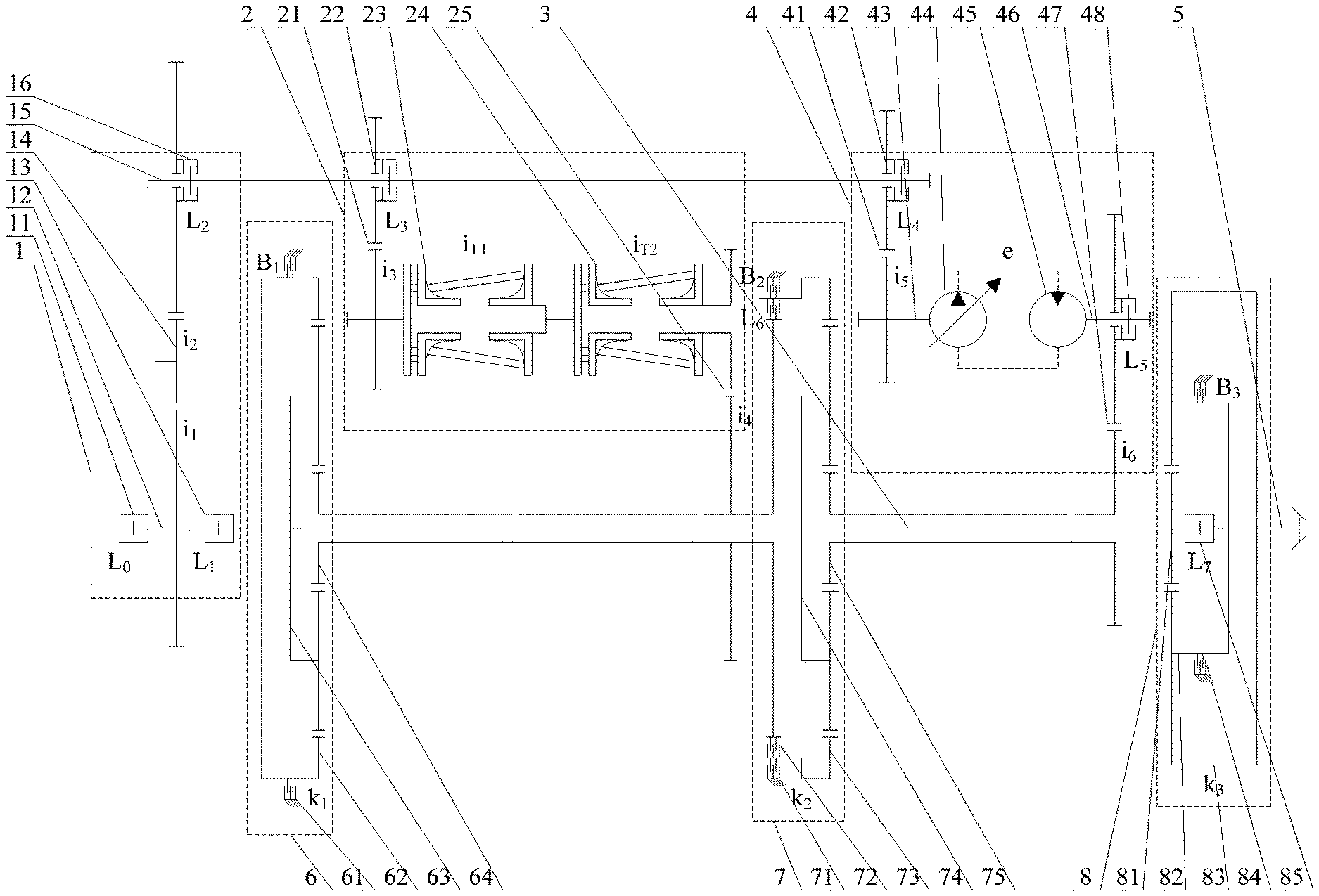
FIG. 1 is a schematic structural diagram of a gear-double ring-hydraulic hybrid transmission device of the present invention.
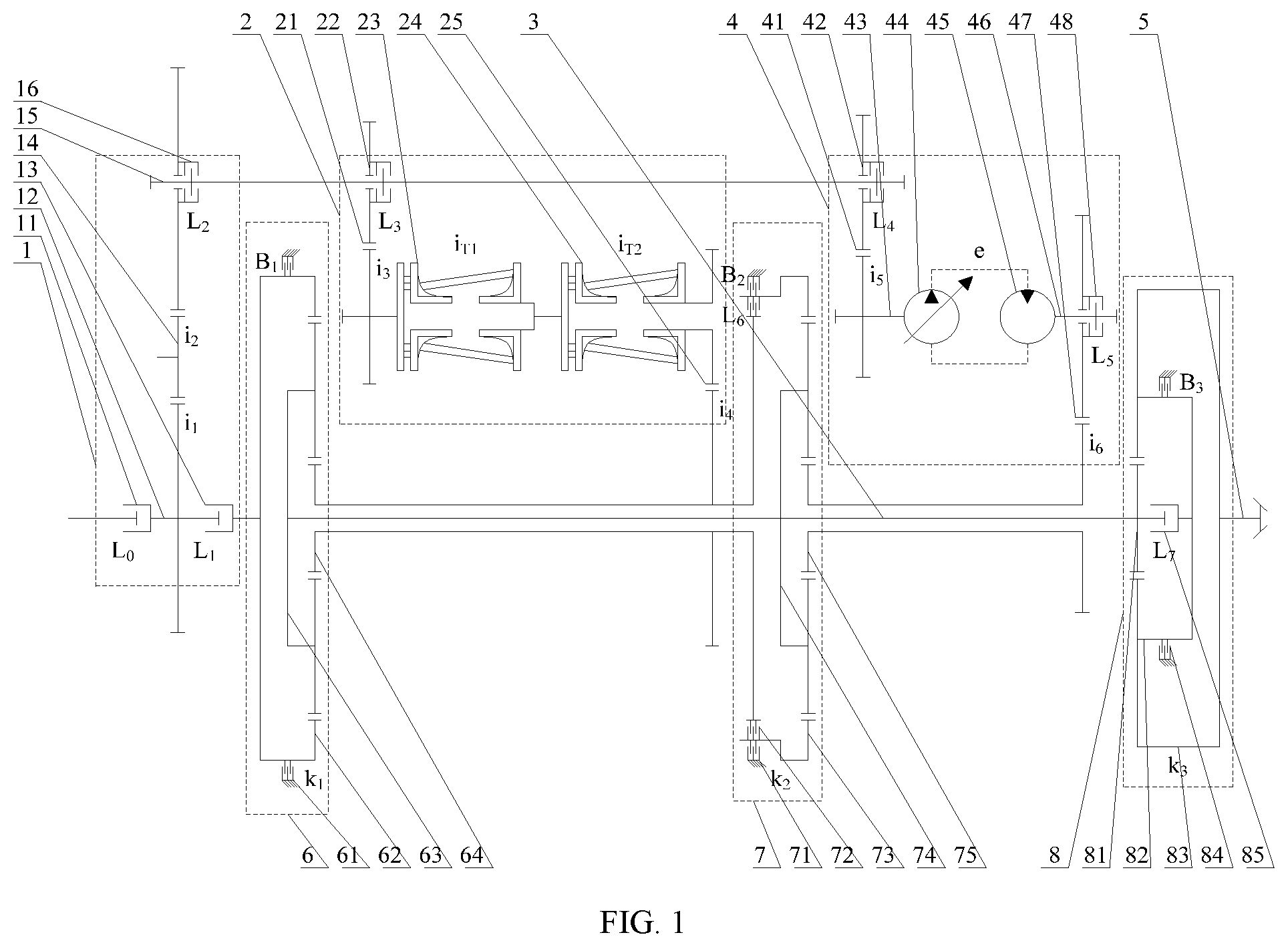
FIG. 2 is a schematic diagram showing the power flow in forward gear single-flow transmission according to the present invention.
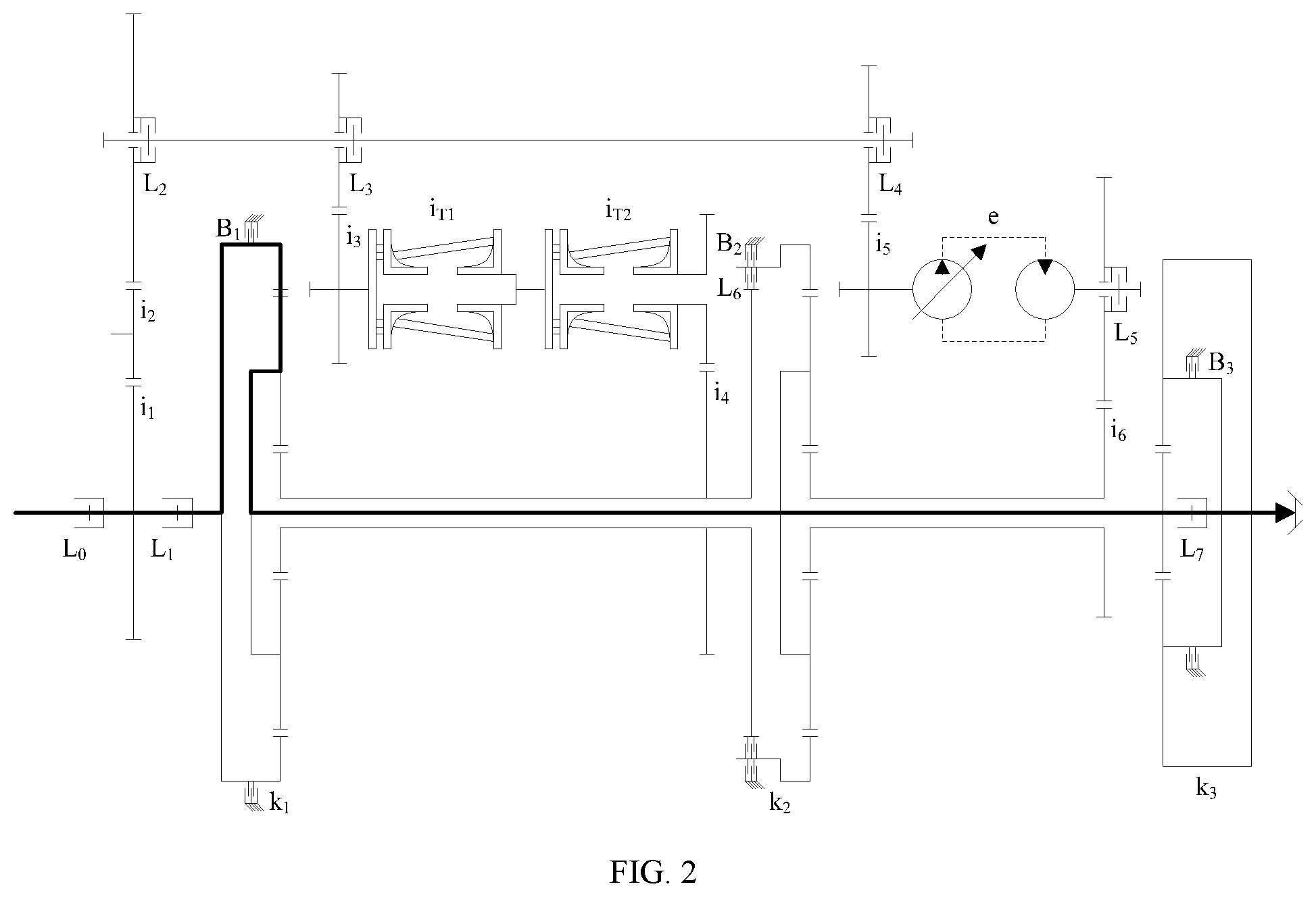
FIG. 3 is a schematic diagram showing the power flow in forward double ring single-flow transmission according to the present invention.
FIG. 4 is a schematic diagram showing the power flow in forward hydraulic single-flow transmission according to the present invention.
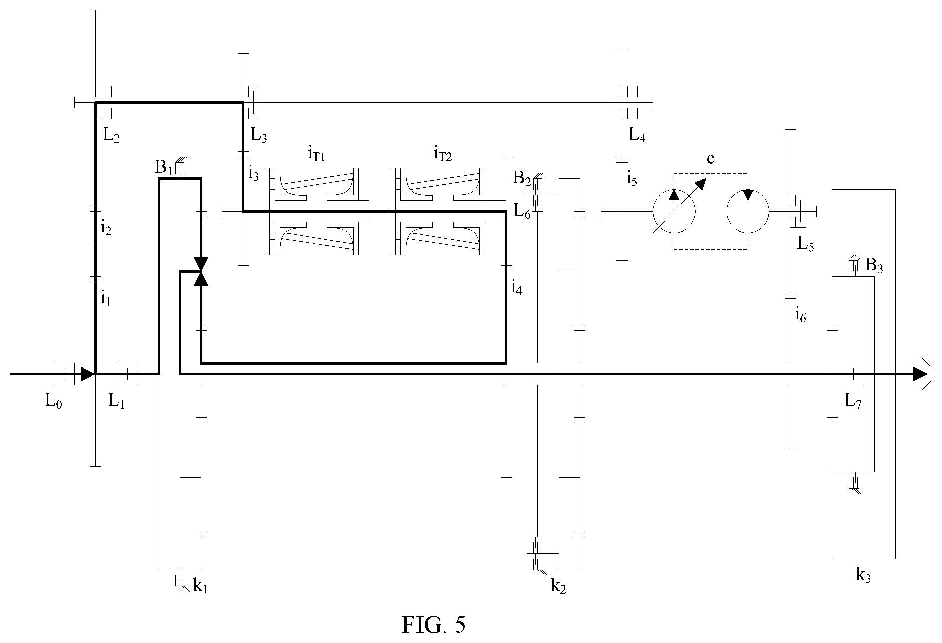
FIG. 5 is a schematic diagram showing the power flow in forward gear-double ring hybrid transmission according to the present invention.
FIG. 6 is a schematic diagram showing the power flow in forward gear-hydraulic hybrid transmission according to the present invention.
FIG. 7 is a schematic diagram showing the power flow in forward double ring-hydraulic hybrid transmission according to the present invention.
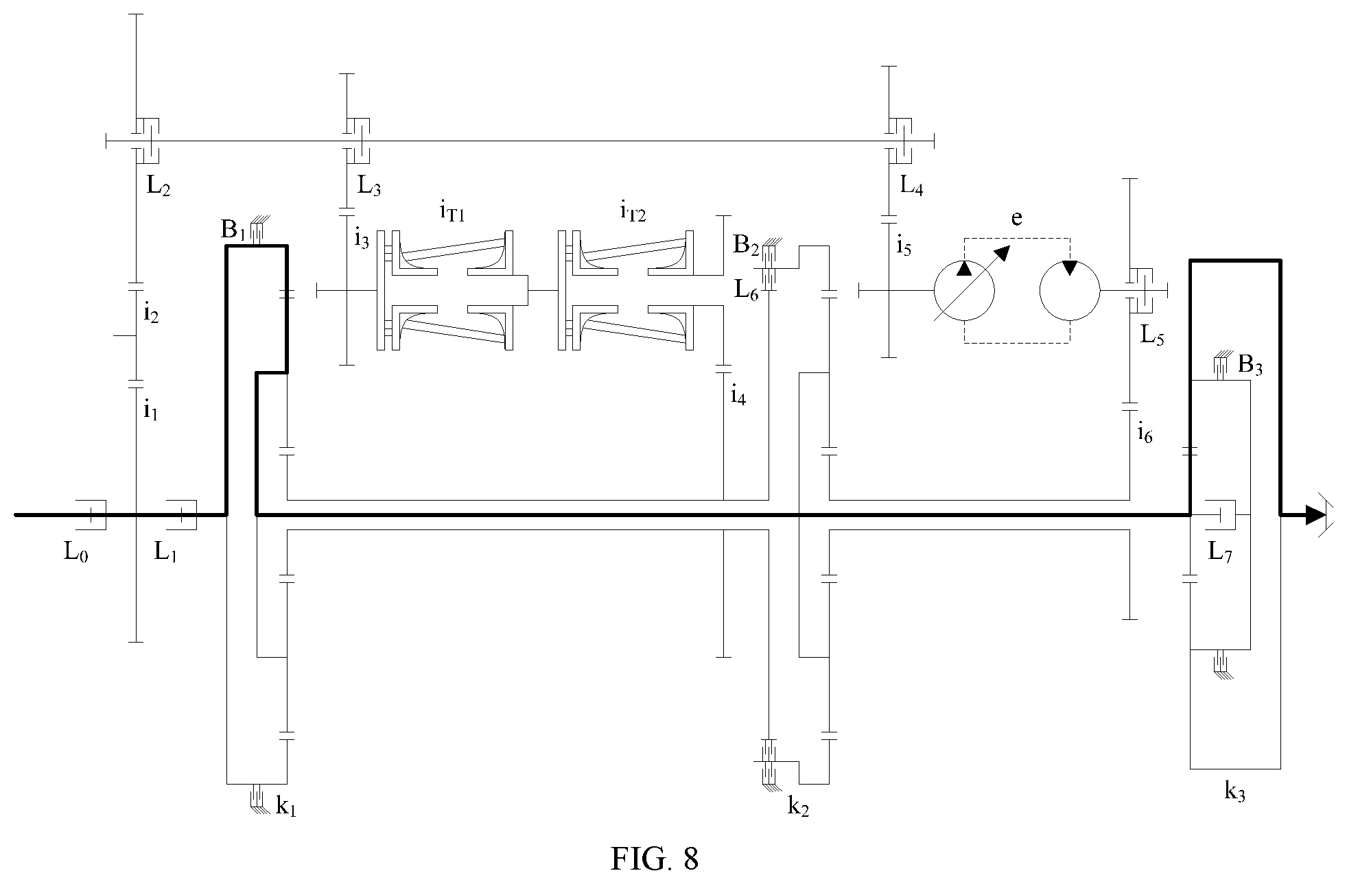
FIG. 8 is a schematic diagram showing the power flow in reverse gear single-flow transmission according to the present invention.
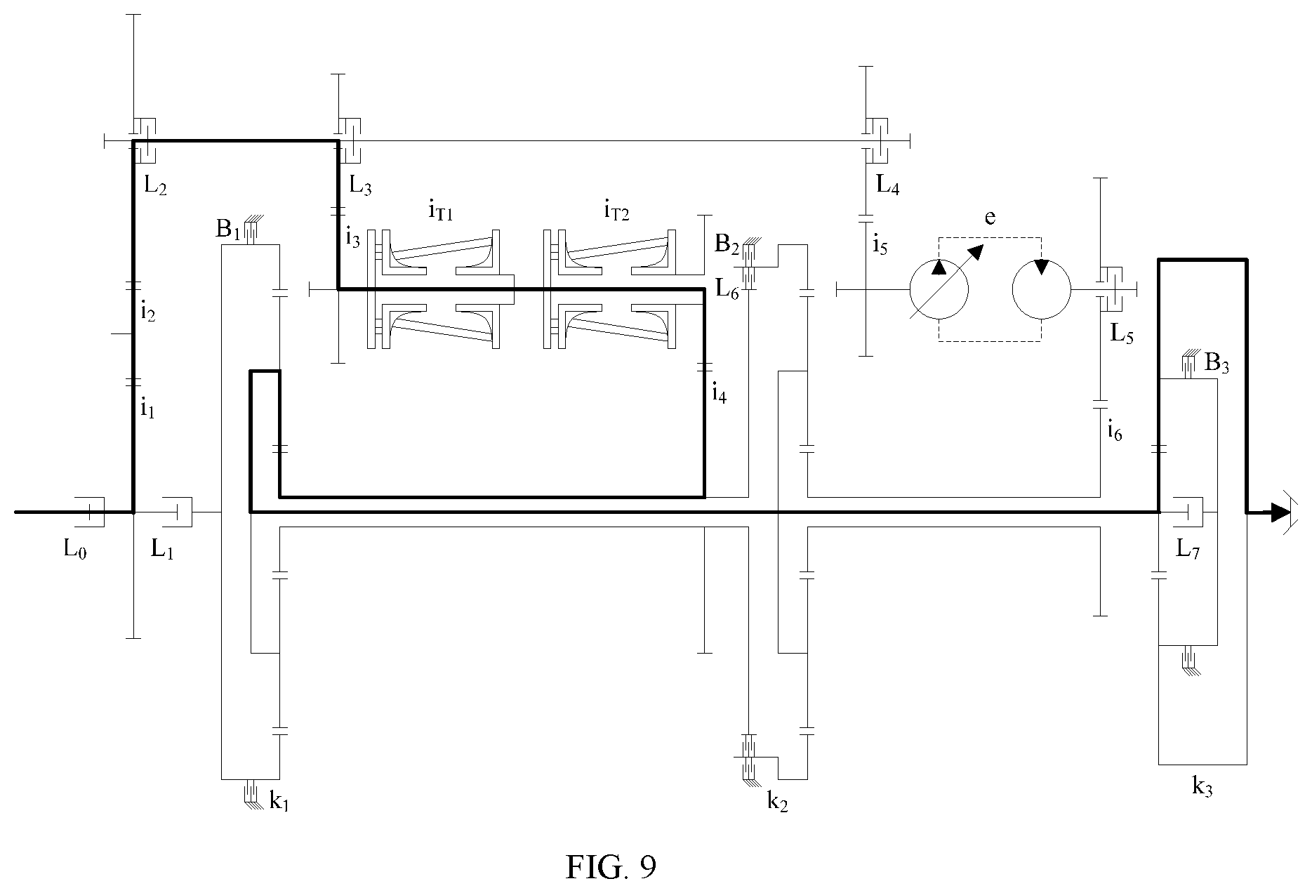
FIG. 9 is a schematic diagram showing the power flow in reverse double ring single-flow transmission according to the present invention.
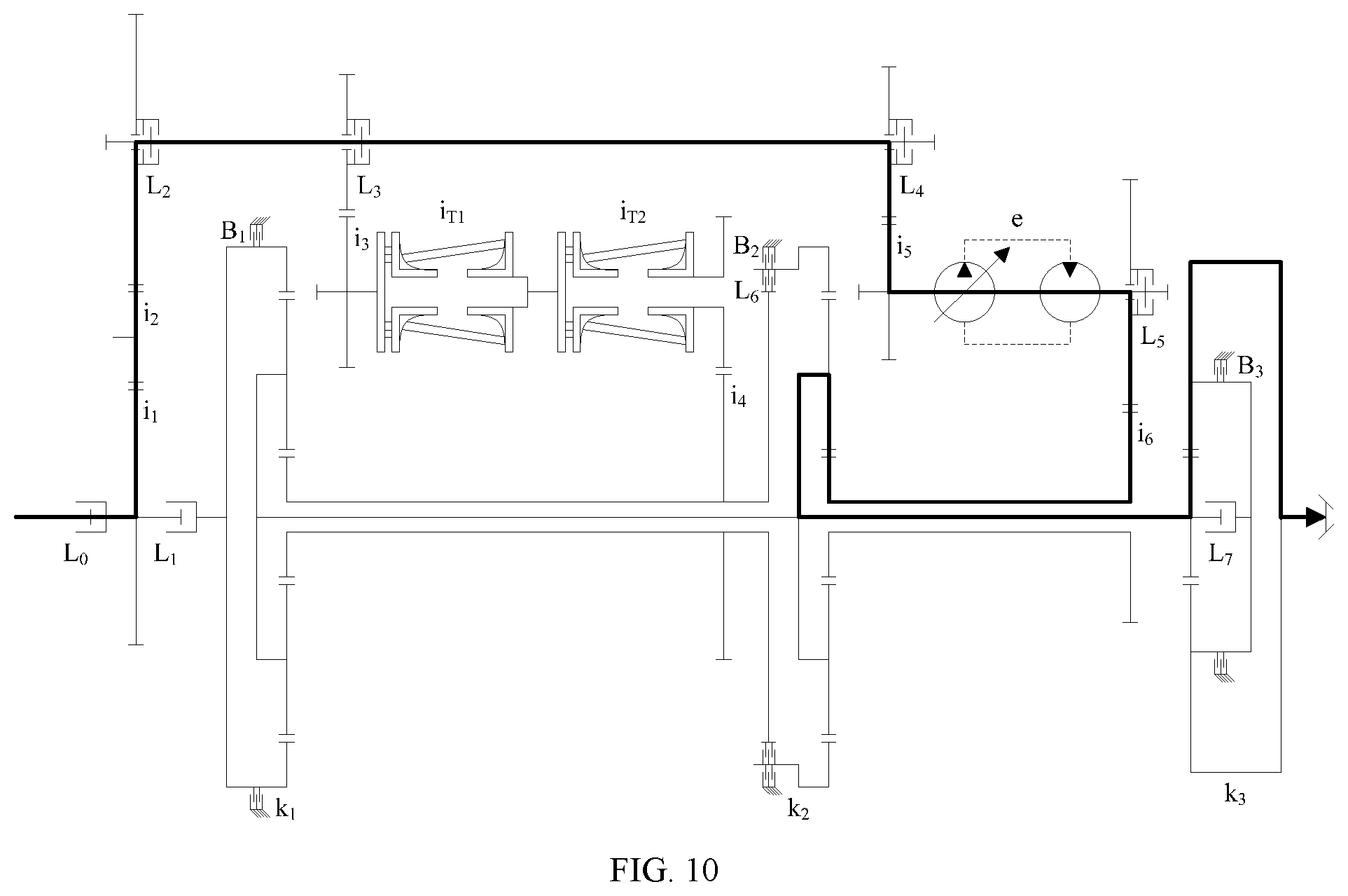
FIG. 10 is a schematic diagram showing the power flow in reverse hydraulic single-flow transmission according to the present invention.
FIG. 11 is a schematic diagram showing the power flow in reverse gear-double ring hybrid transmission according to the present invention.
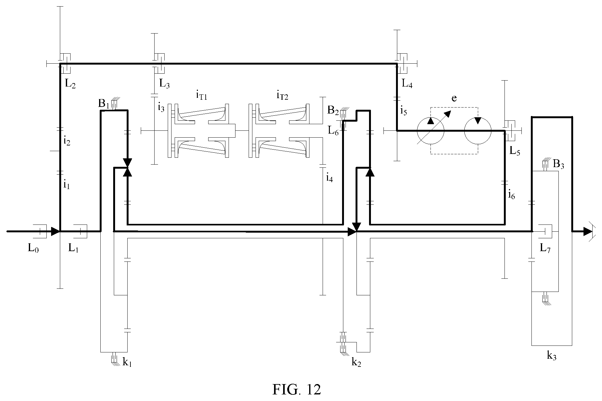
FIG. 12 is a schematic diagram showing the power flow in reverse gear-hydraulic hybrid transmission according to the present invention.
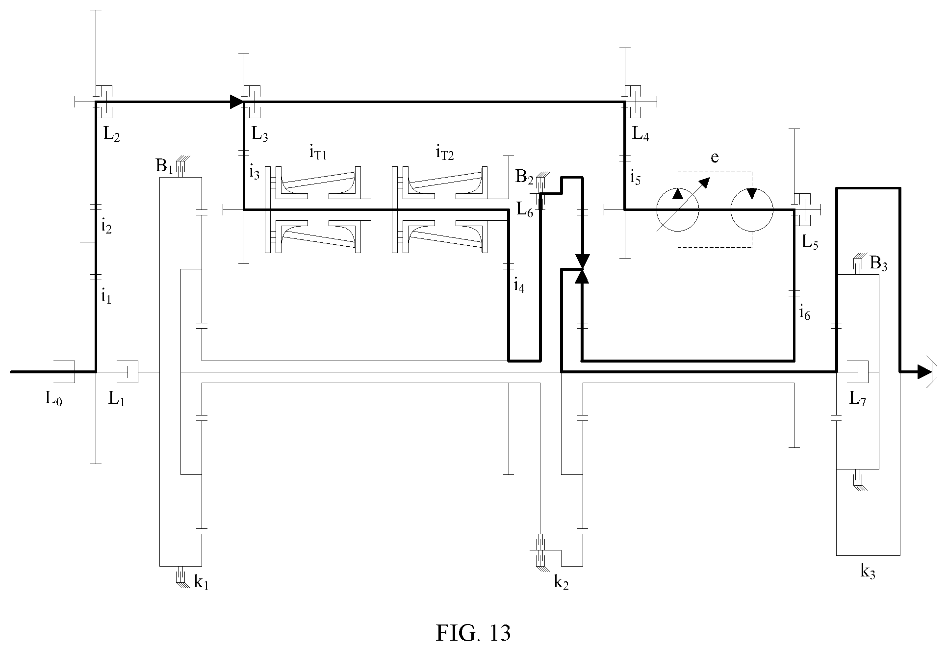
FIG. 13 is a schematic diagram showing the power flow in reverse double ring-hydraulic hybrid transmission according to the present invention.
In the drawings:
1. input mechanism; 11. main clutch L.sub.0; 12. input shaft; 13. clutch L.sub.1; 14. input mechanism gear pair; 15. front shaft; 16. clutch L.sub.2; 2. double ring series transmission mechanism; 21. double ring series transmission mechanism gear pair; 22. clutch L.sub.3; 23. front ring transmission mechanism; 24. rear ring transmission mechanism; 25. double ring series transmission mechanism output gear pair; 3. jackshaft; 4. hydraulic transmission mechanism; 41. hydraulic transmission mechanism input gear pair; 42. clutch L.sub.4; 43. pump shaft; 44. variable displacement pump; 45. quantitative motor; 46. motor shaft; 47. hydraulic transmission mechanism output gear pair; 48. clutch L.sub.5; 5. output shaft; 6. front planetary gear mechanism; 61. brake B.sub.1; 62. front planetary gear mechanism ring gear; 63. front planetary gear mechanism planet carrier; 64. front planetary gear mechanism sun gear; 7. middle planetary gear mechanism; 71. brake B.sub.2; 72. clutch L.sub.6; 73. middle planetary gear mechanism ring gear; 74. middle planetary gear mechanism planet carrier; 75. middle planetary gear mechanism sun gear; 8. rear planetary gear mechanism; 81. rear planetary gear mechanism sun gear; 82. rear planetary gear mechanism planet carrier; 83. rear planetary gear mechanism ring gear; 84. brake B.sub.3; 85. clutch L.sub.7.
DETAILED DESCRIPTION OF THE EMBODIMENTS
The present invention is further described below with reference to the accompanying drawings and specific embodiments, but the protection scope of the present invention is not limited thereto.
As shown in FIG. 1, the gear-double ring-hydraulic hybrid transmission device of the present invention includes an input mechanism 1, a double ring series transmission mechanism 2, a hydraulic transmission mechanism 4, an output shaft 5, a front planetary gear mechanism 6, a middle planetary gear mechanism 7, a rear planetary gear mechanism 8, a clutch assembly, and a brake assembly.
The input mechanism 1 includes a main clutch L.sub.0 11, an input shaft 12, a clutch L.sub.1 13, an input mechanism gear pair 14, a front shaft 15, and a clutch L.sub.2 16. A power source is connected to the input shaft 12 through the main clutch L.sub.0 11, the input shaft 12 is connected to a front planetary gear mechanism ring gear 62 through the clutch L.sub.2 16, and the input shaft 12 is connected to the front shaft 15 through the input mechanism gear pair 14. The power source is transmitted through the main clutch L.sub.0 11 to the input shaft 12 and is then split. One branch of the power is transmitted through the clutch L.sub.1 13 to the front planetary gear mechanism ring gear 62, while the other branch of the power is transmitted through the input mechanism gear pair 14 and the clutch L.sub.2 16 to the front shaft 15. The power arriving in the front shaft 15 can be transmitted through a clutch L.sub.3 22 to an input end of the double ring series transmission mechanism 2 and can also be transmitted through a clutch L.sub.4 42 to an input end of the hydraulic transmission mechanism 4.
The double ring series transmission mechanism 2 includes a double ring series transmission mechanism gear pair 21, the clutch L.sub.3 22, a front ring transmission mechanism 23, a rear ring transmission mechanism 24, and a double ring series transmission mechanism output gear pair 25. The front ring transmission mechanism 23 and the rear ring transmission mechanism 24 are connected in series. In the front ring transmission mechanism 23 or the rear ring transmission mechanism 24, when toroidal surfaces move axially, a roller between the two toroidal surfaces slides along the curved surfaces, so that the angle of the transmission shaft varies to realize changes of the transmission ratio. The front shaft 15 is connected to an input of the front ring transmission mechanism 23 through the double ring series transmission mechanism gear pair 21, and an output of the rear ring transmission mechanism 24 is connected to a front planetary gear mechanism sun gear 64 through the double ring series transmission mechanism output gear pair 25. The clutch L.sub.2 16 and the clutch L.sub.3 22 are together used for selectively connecting the input mechanism 1 to the input end of the double ring series transmission mechanism 2 to achieve synchronous rotation.
The hydraulic transmission mechanism 4 includes a hydraulic transmission mechanism input gear pair 41, the clutch L.sub.4 42, a pump shaft 43, a variable displacement pump 44, a quantitative motor 45, a motor shaft 46, a hydraulic transmission mechanism output gear pair 47, and a clutch L.sub.5 48. The front shaft 15 is connected to the pump shaft 43 through the hydraulic transmission mechanism input gear pair 41, the pump shaft 43 drives the variable displacement pump 44 to work, the variable displacement pump 44 forces the motor shaft 46 of the quantitative motor 45 to rotate, and the motor shaft 46 is connected to a middle planetary gear mechanism sun gear 75 through the hydraulic transmission mechanism output gear pair 47. The clutch L.sub.2 16 and the clutch L.sub.4 42 are together used for selectively connecting the input mechanism 1 to the input end of the hydraulic transmission mechanism 4 to achieve synchronous rotation. The clutch L.sub.5 48 is used for selectively connecting an output end of the hydraulic transmission mechanism 4 to the sun gear of the middle planetary gear mechanism 7 to achieve synchronous rotation.
The jackshaft 3 is fixedly connected to a front planetary gear mechanism planet carrier 63, a middle planetary gear mechanism planet carrier 74, and a rear planetary gear mechanism sun gear 81. The front planetary gear mechanism 6 includes a brake B.sub.1 61, the front planetary gear mechanism ring gear 62, the front planetary gear mechanism planet carrier 63, and the front planetary gear mechanism sun gear 64. The front planetary gear mechanism ring gear 62 is connected to the input shaft 12 through the clutch L.sub.1 13 and is connected to a fixed member through the brake B.sub.1 61. The front planetary gear mechanism sun gear 64 is connected to an output end of the double ring series transmission mechanism 2 and can also be connected to a middle planetary gear mechanism ring gear 73 through a clutch L.sub.6 72. The middle planetary gear mechanism 7 includes a brake B.sub.2 71, the clutch L.sub.6 72, the middle planetary gear mechanism ring gear 73, the middle planetary gear mechanism planet carrier 74, and the middle planetary gear mechanism sun gear 75. The middle planetary gear mechanism ring gear 73 can be connected to the front planetary gear mechanism sun gear 64 through the clutch L.sub.6 72 and can also be connected to a fixed member through the brake B.sub.2 71. The middle planetary gear mechanism sun gear 75 is connected to the output end of the hydraulic transmission mechanism 4. The rear planetary gear mechanism 8 includes the rear planetary gear mechanism sun gear 81, a rear planetary gear mechanism planet carrier 82, a rear planetary gear mechanism ring gear 83, a brake B.sub.3 84, and a clutch L.sub.7 85. The rear planetary gear mechanism planet carrier 82 can be connected to the rear planetary gear mechanism sun gear 81 through the clutch L.sub.7 85 and can also be connected to a fixed member through the brake B.sub.3 84. The rear planetary gear mechanism ring gear 83 is connected to the output shaft 5.
Transmission modes including gear single-flow transmission, double ring single-flow transmission, hydraulic single-flow transmission, gear-double ring hybrid transmission, gear-hydraulic hybrid transmission, and double ring-hydraulic hybrid transmission are provided between the input mechanism and the output member by adjusting a transmission ratio of the double ring series transmission mechanism 2 and a displacement ratio of the hydraulic transmission mechanism 4 and selectively controlling engagement of the clutch assembly and the brake assembly. Specific examples are given below for illustration with reference to Table 1:
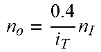
As shown in FIG. 2 and FIG. 8, the gear single-flow transmission includes forward and reverse gear single-flow transmission.
The forward gear single-flow transmission is shown in FIG. 2, wherein when the main clutch L.sub.0 11, the clutch L.sub.1 13, the clutch L.sub.6 72, the clutch L.sub.7 85, and the brake B.sub.2 71 are engaged, power is transmitted through the main clutch L.sub.0 11, the input shaft 12, the clutch L.sub.1 13, the front planetary gear mechanism ring gear 62, and the front planetary gear mechanism planet carrier 63 to the jackshaft 3, then passes through the rear planetary gear mechanism 8 that is fixedly connected as a whole, and is output from the output shaft 5. In this case, the rotation speeds of the output shaft and the input shaft are in the following relationship:
.times. ##EQU00001##
wherein n.sub.o is the rotation speed of the output shaft 5, n.sub.1 is the rotation speed of the input shaft 12, and k.sub.1 is a characteristic parameter of the front planetary gear mechanism.
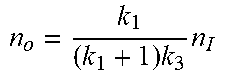
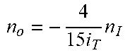
The reverse gear single-flow transmission is shown in FIG. 8, wherein when the main clutch L.sub.0 11, the clutch L.sub.1 13, the clutch L.sub.6 72, the brake B.sub.2 71, and the brake B.sub.3 84 are engaged, power is transmitted through the main clutch L.sub.0 11, the input shaft 12, the clutch L.sub.1 13, the front planetary gear mechanism ring gear 62, and the front planetary gear mechanism planet carrier 63 to the jackshaft 3, then passes through the rear planetary gear mechanism sun gear 81 and the rear planetary gear mechanism ring gear 83, and is output from the output shaft 5. In this case, the rotation speeds of the output shaft and the input shaft are in the following relationship:
.times..times. ##EQU00002##
wherein k.sub.3 is a characteristic parameter of the rear planetary gear mechanism.
As shown in FIG. 3 and FIG. 9, the double ring single-flow transmission includes forward and reverse double ring single-flow transmission.
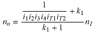
The forward double ring single-flow transmission is shown in FIG. 3, wherein when the main clutch L.sub.0 11, the clutch L.sub.2 16, the clutch L.sub.3 22, the clutch L.sub.7 85, and the brake B.sub.1 61 are engaged, power is transmitted through the input mechanism 1, the double ring series transmission mechanism 2, the front planetary gear mechanism sun gear 64, and the front planetary gear mechanism planet carrier 63 to the jackshaft 3, then passes through the rear planetary gear mechanism 8 that is fixedly connected as a whole, and is output from the output shaft 5. In this case, the rotation speeds of the output shaft and the input shaft are in the following relationship:
.times..times..times..times..times..times..times..times..times..function.- .times..times. ##EQU00003##
wherein i.sub.1i.sub.2 is a transmission ratio between the input shaft 12 and the front shaft 15, i.sub.3 is a transmission ratio of the double ring series transmission mechanism gear pair 21, i.sub.4 is a transmission ratio of the double ring series transmission mechanism output gear pair 25, i.sub.T1 is a transmission ratio of the front ring transmission mechanism 23, i.sub.T1.di-elect cons.[0.5, 2.0]; i.sub.T2 is a transmission ratio of the rear ring transmission mechanism, i.sub.T2.di-elect cons.[0.5, 2.0]. Then, i.sub.Ti.sub.T1i.sub.T2.di-elect cons.[0.25, 4.00].
The reverse double ring single-flow transmission is shown in FIG. 9, wherein when the main clutch L.sub.0 11, the clutch L.sub.2 16, the clutch L.sub.3 22, the brake B.sub.1 61, and the brake B.sub.3 84 are engaged, power is transmitted through the input mechanism 1, the double ring series transmission mechanism 2, the front planetary gear mechanism sun gear 64, and the front planetary gear mechanism planet carrier 63 to the jackshaft 3, then passes through the rear planetary gear mechanism sun gear 81 and the rear planetary gear mechanism ring gear 83, and is output from the output shaft 5. In this case, the rotation speeds of the output shaft and the input shaft are in the following relationship:
.times..times..times..times..times..times..times..times..times..function.- .times..times..times. ##EQU00004##
As shown in FIG. 4 and FIG. 10, the hydraulic single-flow transmission includes forward and reverse hydraulic single-flow transmission.
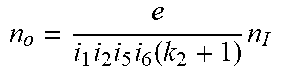
The forward hydraulic single-flow transmission is shown in FIG. 4, wherein when the main clutch L.sub.4 11, the clutch L.sub.2 16, the clutch L.sub.4 42, the clutch L.sub.1 48, the clutch L.sub.6 72, the clutch L.sub.7 85, and the brake B.sub.2 71 are engaged, power is transmitted through the input mechanism 1, the hydraulic transmission mechanism 4, the middle planetary gear mechanism sun gear 75, and the middle planetary gear mechanism planet carrier 74 to the jackshaft 3, then passes through the rear planetary gear mechanism 8 that is fixedly connected as a whole, and is output from the output shaft 5. In this case, the rotation speeds of the output shaft and the input shaft are in the following relationship:
.times..times..times..function..times. ##EQU00005##
wherein i.sub.5 is a transmission ratio of the hydraulic transmission mechanism input gear pair 41, i.sub.6 is a transmission ratio of the hydraulic transmission mechanism output gear pair 47, k.sub.2 is a characteristic parameter of the middle planetary gear mechanism, and e is a displacement ratio of the hydraulic transmission mechanism, e.di-elect cons.[0, 1.0].
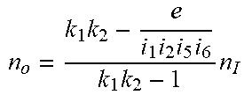
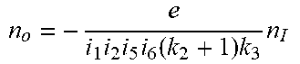
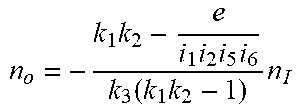
The reverse hydraulic single-flow transmission is shown in FIG. 10, wherein when the main clutch L.sub.0 11, the clutch L.sub.2 16, the clutch L.sub.4 42, the clutch L.sub.5 48, the clutch L.sub.6 72, the brake B.sub.2 71, and the brake B.sub.3 84 are engaged, power is transmitted through the input mechanism 1, the hydraulic transmission mechanism 4, the middle planetary gear mechanism sun gear 75, and the middle planetary gear mechanism planet carrier 74 to the jackshaft 3, then passes through the rear planetary gear mechanism sun gear 81 and the rear planetary gear mechanism ring gear 83, and is output from the output shaft 5. In this case, the rotation speeds of the output shaft and the input shaft are in the following relationship:
.times..times..times..function..times..times. ##EQU00006##
As shown in FIG. 5 and FIG. 11, the gear-double ring hybrid transmission includes forward and reverse gear-double ring hybrid transmission.
The forward gear-double ring hybrid transmission is shown in FIG. 5, wherein when the main clutch L.sub.0 11, the clutch L.sub.1 13, the clutch L.sub.2 16, the clutch L.sub.3 22, and the clutch L.sub.7 85 are engaged, power passes through the main clutch L.sub.0 11 and the input shaft 12 and is then split. One branch of the power is transmitted through the input mechanism gear pair 14, the clutch L.sub.2 16, the front shaft 15, and the double ring series transmission mechanism 2 to the front planetary gear mechanism sun gear 64, while the other branch of the power is directly transmitted through the clutch L.sub.1 13 to the front planetary gear mechanism ring gear 62. The hybrid power is transmitted through the front planetary gear mechanism planet carrier 63 to the jackshaft 3, then passes through the rear planetary gear mechanism 8 that is fixedly connected as a whole, and is output from the output shaft 5. In this case, the rotation speeds of the output shaft and the input shaft are in the following relationship:
.times..times..times..times..times..times..times..times..times..times..ti- mes. ##EQU00007##
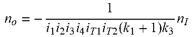
The reverse gear-double ring hybrid transmission is shown in FIG. 11, wherein when the main clutch L.sub.0 11, the clutch L.sub.1 13, the clutch L.sub.2 16, the clutch L.sub.3 22, and the brake B.sub.3 84 are engaged, power passes through the main clutch L.sub.0 11 and the input shaft 12 and is then split. One branch of the power is transmitted through the input mechanism gear pair 14, the clutch L.sub.2 16, the front shaft 15, and the double ring series transmission mechanism 2 to the front planetary gear mechanism sun gear 64, while the other branch of the power is directly transmitted through the clutch L.sub.1 13 to the front planetary gear mechanism ring gear 62. The hybrid power is transmitted through the front planetary gear mechanism planet carrier 63 to the jackshaft 3, then passes through the rear planetary gear mechanism sun gear 81 and the rear planetary gear mechanism ring gear 83, and is output from the output shaft 5. In this case, the rotation speeds of the output shaft and the input shaft are in the following relationship:
.times..times..times..times..times..times..times..times..times..times..ti- mes..times. ##EQU00008##
As shown in FIG. 6 and FIG. 12, the gear-hydraulic hybrid transmission includes forward and reverse gear-hydraulic hybrid transmission.
The forward gear-hydraulic hybrid transmission is shown in FIG. 6, wherein when the main clutch L.sub.0 11, the clutch L.sub.1 13, the clutch L.sub.2 16, the clutch L.sub.4 42, the clutch L.sub.5 48, the clutch L.sub.6 72, and the clutch L.sub.7 85 are engaged, the front planetary gear mechanism sun gear 64 is connected to the middle planetary gear mechanism ring gear 73, the front planetary gear mechanism planet carrier 63 is connected to the middle planetary gear mechanism planet carrier 74, and power passes through the main clutch L.sub.0 11 and the input shaft 12 and is then split. One branch of the power is directly transmitted through the clutch L.sub.1 13 to the front planetary gear mechanism ring gear 62, while the other branch of the power is transmitted through the input mechanism gear pair 14, the clutch L.sub.2 16, the front shaft 15, and the hydraulic transmission mechanism 4 to the middle planetary gear mechanism sun gear 75. Then, the power is split again. A first sub-branch of the power is transmitted to the middle planetary gear mechanism planet carrier 74, while a second sub-branch of the power is transmitted through the middle planetary gear mechanism ring gear 73 to the front planetary gear mechanism sun gear 64. The mechanical power flow transmitted to the front planetary gear mechanism ring gear 62 and the hydraulic power flow transmitted to the front planetary gear mechanism sun gear 64 are converged at the front planetary gear mechanism planet carrier 63, and are further converged with the hydraulic power flow transmitted to the middle planetary gear mechanism planet carrier 74. After that, the power is transmitted to the jackshaft 3, then passes through the rear planetary gear mechanism 8 that is fixedly connected as a whole, and is output from the output shaft 5. In this case, the rotation speeds of the output shaft and the input shaft are in the following relationship:
.times..times..times..times..times..times. ##EQU00009##
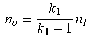
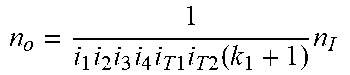
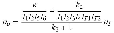
The reverse gear-hydraulic hybrid transmission is shown in FIG. 12, wherein when the main clutch L.sub.0 11, the clutch L.sub.1 13, the clutch L.sub.2 16, the clutch L.sub.4 42, the clutch L.sub.5 48, the clutch L.sub.6 72, and the brake B.sub.3 84 are engaged, the front planetary gear mechanism sun gear 64 is connected to the middle planetary gear mechanism ring gear 73, the front planetary gear mechanism planet carrier 63 is connected to the middle planetary gear mechanism planet carrier 74, and power passes through the main clutch L.sub.0 11 and the input shaft 12 and is then split. One branch of the power is directly transmitted through the clutch L.sub.1 13 to the front planetary gear mechanism ring gear 62, while the other branch of the power is transmitted through the input mechanism gear pair 14, the clutch L.sub.2 16, the front shaft 15, and the hydraulic transmission mechanism 4 to the middle planetary gear mechanism sun gear 75. Then, the power is split again. A first sub-branch of the power is transmitted to the middle planetary gear mechanism planet carrier 74, while a second sub-branch of the power is transmitted through the middle planetary gear mechanism ring gear 73 to the front planetary gear mechanism sun gear 64. The mechanical power flow transmitted to the front planetary gear mechanism ring gear 62 and the hydraulic power flow transmitted to the front planetary gear mechanism sun gear 64 are converged at the front planetary gear mechanism planet carrier 63, and are further converged with the hydraulic power flow transmitted to the middle planetary gear mechanism planet carrier 74. After that, the power is transmitted to the jackshaft 3, then passes through the rear planetary gear mechanism sun gear 81 and the rear planetary gear mechanism ring gear 83, and is output from the output shaft 5. In this case, the rotation speeds of the output shaft and the input shaft are in the following relationship:
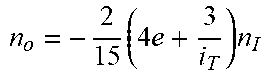
.times..times..times..times..function..times..times. ##EQU00010##
As shown in FIG. 7 and FIG. 13, the double ring-hydraulic hybrid transmission includes forward and reverse double ring-hydraulic hybrid transmission.
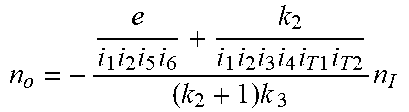
The forward double ring-hydraulic hybrid transmission is shown in FIG. 7, wherein when the main clutch L.sub.0 11, the clutch L.sub.2 16, the clutch L.sub.3 22, the clutch L.sub.4 42, the clutch L.sub.5 48, the clutch L.sub.6 72, and the clutch L.sub.7 85 are engaged, power passes through the input mechanism 1 and is then split. One branch of the power is transmitted through the double ring series transmission mechanism 2 to the middle planetary gear mechanism ring gear 73, while the other branch of the power is transmitted through the hydraulic transmission mechanism 4 to the middle planetary gear mechanism sun gear 75. The hybrid power is transmitted through the middle planetary gear mechanism planet carrier 74 to the jackshaft 3, then passes through the rear planetary gear mechanism 8 that is fixedly connected as a whole, and is output from the output shaft 5. In this case, the rotation speeds of the output shaft and the input shaft are in the following relationship:
.times..times..times..times..times..times..times..times..times..times..ti- mes..times..times. ##EQU00011##
The reverse double ring-hydraulic hybrid transmission is shown in FIG. 13, wherein when the main clutch L.sub.0 11, the clutch L.sub.2 16, the clutch L.sub.3 22, the clutch L.sub.4 42, the clutch L.sub.5 48, the clutch L.sub.6 72, and the brake B.sub.3 84 are engaged, power passes through the input mechanism 1 and is then split. One branch of the power is transmitted through the double ring series transmission mechanism 2 to the middle planetary gear mechanism ring gear 73, while the other branch of the power is transmitted through the hydraulic transmission mechanism 4 to the middle planetary gear mechanism sun gear 75. The hybrid power is transmitted through the middle planetary gear mechanism planet carrier 74 to the jackshaft 3, then passes through the rear planetary gear mechanism sun gear 81 and the rear planetary gear mechanism ring gear 83, and is output from the output shaft 5. In this case, the rotation speeds of the output shaft and the input shaft are in the following relationship:
.times..times..times..times..times..times..times..times..times..times..ti- mes..times..times..times. ##EQU00012##
TABLE-US-00001 TABLE 1 Engagement/disengagement of each component Trans- mission Direc- Execution component type tion L.sub.0 L.sub.1 L.sub.2 L.sub.3 L.sub.4 L.sub.5 L.sub.6 L.sub.7 - B.sub.1 B.sub.2 B.sub.3 Gear single- Forward .tangle-solidup. .tangle-solidup. .DELTA. .DELTA. .DE- LTA. .DELTA. .tangle-solidup. .tangle-solidup. .DELTA. .tangle-solidup. .D- ELTA. flow Double ring .tangle-solidup. .DELTA. .tangle-solidup. .tangle-solidup. .D- ELTA. .DELTA. .DELTA. .tangle-solidup. .tangle-solidup. .DELTA. .DELTA. single-flow Hydraulic .tangle-solidup. .DELTA. .tangle-solidup. .DELTA. .tangle-solid- up. .tangle-solidup. .tangle-solidup. .tangle-solidup. .DELTA. .tangle-sol- idup. .DELTA. single-flow Gear-double .tangle-solidup. .tangle-solidup. .tangle-solidup. .tangle-solidup. .DE- LTA. .DELTA. .DELTA. .tangle-solidup. .DELTA. .DELTA. .DELTA. ring hybrid Gear- .tangle-solidup. .tangle-solidup. .tangle-solidup. .DELTA. .tangle-- solidup. .tangle-solidup. .tangle-solidup. .tangle-solidup. .DELTA. .DELTA- . .DELTA. hydraulic hybrid Double .tangle-solidup. .DELTA. .tangle-solidup. .tangle-solidup. .tangle- -solidup. .tangle-solidup. .tangle-solidup. .tangle-solidup. .DELTA. .DELT- A. .DELTA. ring- hydraulic hybrid Gear single- Reverse .tangle-solidup. .tangle-solidup. .DELTA. .DELTA. .DE- LTA. .DELTA. .tangle-solidup. .DELTA. .DELTA. .tangle-solidup. .tangle-sol- idup. flow Double ring .tangle-solidup. .DELTA. .tangle-solidup. .tangle-solidup. .D- ELTA. .DELTA. .DELTA. .DELTA. .tangle-solidup. .DELTA. .tangle-solidup. single-flow Hydraulic .tangle-solidup. .DELTA. .tangle-solidup. .DELTA. .tangle-solid- up. .tangle-solidup. .tangle-solidup. .DELTA. .DELTA. .tangle-solidup. .ta- ngle-solidup. single-flow Gear-double .tangle-solidup. .tangle-solidup. .tangle-solidup. .tangle-solidup. .DE- LTA. .DELTA. .DELTA. .DELTA. .DELTA. .DELTA. .tangle-solidup. ring hybrid Gear- .tangle-solidup. .tangle-solidup. .tangle-solidup. .DELTA. .tangle-- solidup. .tangle-solidup. .tangle-solidup. .DELTA. .DELTA. .DELTA. .tangle- -solidup. hydraulic hybrid Double .tangle-solidup. .DELTA. .tangle-solidup. .tangle-solidup. .tangle- -solidup. .tangle-solidup. .tangle-solidup. .DELTA. .DELTA. .DELTA. .tangl- e-solidup. ring- hydraulic hybrid
In Table 1: 1. B stands for brake, and L stands for clutch; 2. .diamond-solid. stands for engagement of a gear-shift component, and .DELTA. stands for disengagement of a gear-shift component.
In an embodiment, the following parameters are selected: k.sub.1=k.sub.2=k.sub.3=1.5, i.sub.1i.sub.2i.sub.3i.sub.4=1.0, i.sub.1i.sub.2i.sub.5i.sub.6=0.5, i.sub.T1.di-elect cons.[0.5, 2.0], and i.sub.T=i.sub.T1i.sub.T2.di-elect cons.[0.25, 4.00].
In this case, the relational expressions of the rotation speeds of the output shaft and the input shaft and the speed regulation ranges thereof are shown in Table 2.
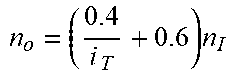
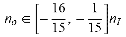
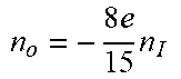
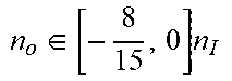
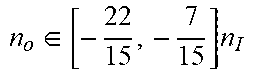
TABLE-US-00002 TABLE 2 Relational expressions of the rotation speeds of the output shaft and the input shaft and speed regulation ranges thereof Transmission Relational expressions of the rotation speeds of type the output shaft and the input shaft Speed regulation range Gear single-flow (forward) .times. ##EQU00013## n.sub.o = 0.6n.sub.I n.sub.o = 0.6n.sub.I Double ring single-flow (forward) .times..times..times..times..times..times..times..times..times.- .function..times. ##EQU00014## .times. ##EQU00015## n.sub.o.di-elect cons. [0.1, 1.6]n.sub.I Hydraulic single-flow (forward) .times..times..times..function..times. ##EQU00016## n.sub.o = 0.8en.sub.I n.sub.o.di-elect cons. [0, 0.8]n.sub.I Gear-double ring hybrid (forward) .times..times..times..times..times..times..times..times..times.- .times. ##EQU00017## .times..times. ##EQU00018## n.sub.0.di-elect cons. [0.7, 2.2]n.sub.I Gear-hydraulic hybrid (forward) .times..times..times..times..times..times. ##EQU00019## n.sub.o = (1.8 - 1.6e)n.sub.I n.sub.o.di-elect cons.[0.2, 1.8]n.sub.I Double ring-hydraulic hybrid (forward) .times..times..times..times..times..times..times..times..times.- .times..times..times..times. ##EQU00020## .times..times. ##EQU00021## n.sub.o.di-elect cons.[0.15, 3.2]n.sub.I Gear single-flow (reverse) .times..times. ##EQU00022## n.sub.o = -0.4n.sub.I n.sub.o = -0.4n.sub.I Double ring single-flow (reverse) .times..times..times..times..times..times..times..times..times.- .function..times..times. ##EQU00023## .times..times..times. ##EQU00024## .di-elect cons..times. ##EQU00025## Hydraulic single-flow (reverse) .times..times..times..function..times..times. ##EQU00026## .times..times..times. ##EQU00027## .di-elect cons..times. ##EQU00028## Gear-double ring hybrid (reverse) .times..times..times..times..times..times..times..times..times.- .times..times. ##EQU00029## .times..times. ##EQU00030## .di-elect cons..times. ##EQU00031## Gear-hydraulic hybrid (reverse) .times..times..times..times..function..times..times. ##EQU00032## .times..times..times..times. ##EQU00033## .di-elect cons..times. ##EQU00034## Double ring-hydraulic hybrid (reverse) .times..times..times..times..times..times..times..times..times.- .times..times..times..times..times..times. ##EQU00035## .times..times..times..times. ##EQU00036## .di-elect cons..times. ##EQU00037##
According to the embodiment in FIG. 1, i.sub.T1=i.sub.1i.sub.2i.sub.3 is a transmission ratio between the input shaft 12 and the double ring series transmission mechanism 2; i.sub.TO=i.sub.4 is a transmission ratio between the double ring series transmission mechanism 2 and the front planetary gear mechanism sun gear; i.sub.H1=i.sub.1i.sub.2i.sub.5 is a transmission ratio between the input shaft 12 and the hydraulic transmission mechanism 4, and i.sub.HO=i.sub.6 is a transmission ratio between the output of the hydraulic transmission mechanism and the rear planetary gear mechanism sun gear.
The hydraulic single-flow transmission is adopted for startup, and when e.di-elect cons.[0, 1],
.di-elect cons..times..function..times. ##EQU00038##
when
.times..times..function. ##EQU00039## and e.di-elect cons.[0, 1], the hydraulic single-flow transmission is configured for being synchronously switched to the gear single-flow transmission; when
.times..function..times..times..times..times..times..times..times..functi- on. ##EQU00040## e.di-elect cons.[0, 1], and i.sub.T1, i.sub.T2.di-elect cons.[0.5, 2.0], the hydraulic single-flow transmission is configured for being synchronously switched to the double ring single-flow transmission; when
.times..function..times..times..times..times..times..times..times..times.- .times..times..times..times..times..times..times..times..times. ##EQU00041## e.di-elect cons.[0, 1], and i.sub.T1, i.sub.T.di-elect cons.[0.5, 2.0], the hydraulic single-flow transmission is configured for being synchronously switched to the gear-double ring dual-flow transmission; when
.times..times..function..times. ##EQU00042## the hydraulic single-flow transmission is configured for being synchronously switched to the gear-hydraulic dual-flow transmission; the hydraulic single-flow transmission is configured for being switched to the double ring-hydraulic dual-flow transmission at any point, and in this case, synchronous switching cannot be implemented, but the speed regulation range is expanded;
the double ring single-flow transmission is configured for being switched to the gear-double ring dual-flow transmission at any point, and in this case, synchronous switching cannot be implemented, but the speed regulation range is expanded; when
.times..times..times..times..function..times..times..times..times..times.- .times..times..times..function. ##EQU00043## e.di-elect cons.[0, 1], and i.sub.T1, i.sub.T2.di-elect cons.[0.5, 2.0], the double ring single-flow transmission is configured for being synchronously switched to the gear-hydraulic dual-flow transmission;
when
.times..times..times..times..times..times..times..times..times..times..fu- nction. ##EQU00044## e.di-elect cons.[0, 1], and i.sub.T1, i.sub.T2.di-elect cons.[0.5, 2.0], the gear-double ring dual-flow transmission is configured for being synchronously switched with the gear-hydraulic dual-flow transmission;
when
.times..times..times..times..times..times..times..times..times..times..ti- mes. ##EQU00045## e.di-elect cons.[0, 1], and i.sub.T1, i.sub.T2.di-elect cons.[0.5, 2.0], the gear-double ring dual-flow transmission is configured for being synchronously switched with the double ring-hydraulic dual-flow transmission;
when
.times..times..times..times..times..times..times..times..times..times..ti- mes. ##EQU00046## e.di-elect cons.[0, 1], and i.sub.T1, i.sub.T2.di-elect cons.[0.5, 2.0], the gear-hydraulic dual-flow transmission is configured for being synchronously switched with the double ring-hydraulic dual-flow transmission.
Embodiment
The hydraulic single-flow transmission is adopted for startup, and when e.di-elect cons.[0, 1], n.sub.o.di-elect cons.[0, 0.8]n.sub.I,
when e=0.75, the hydraulic single-flow transmission is configured for being synchronously switched to the gear single-flow transmission; when ei.sub.T=0.5, e.di-elect cons.[0, 1], and i.sub.T.di-elect cons.[0.25, 4], the hydraulic single-flow transmission is configured for being synchronously switched to the double ring single-flow transmission; when
.times. ##EQU00047## e.di-elect cons.[0, 1], and i.sub.T.di-elect cons.[0.25, 4], the hydraulic single-flow transmission is configured for being synchronously switched to the gear-double ring dual-flow transmission; when e=0.75, the hydraulic single-flow transmission is configured for being synchronously switched to the gear-hydraulic dual-flow transmission; the hydraulic single-flow transmission is configured for being switched to the double ring-hydraulic dual-flow transmission at any point, and in this case, synchronous switching cannot be implemented, but the speed regulation range is expanded;
the double ring single-flow transmission is configured for being switched to the gear-double ring dual-flow transmission at any point, and in this case, synchronous switching cannot be implemented, but the speed regulation range is expanded; when
.times. ##EQU00048## e.di-elect cons.[0, 1], and i.sub.T.di-elect cons.[0.25, 4], the double ring single-flow transmission is configured for being synchronously switched to the gear-hydraulic dual-flow transmission;
when
.times. ##EQU00049## e.di-elect cons.[0, 1], and i.sub.T.di-elect cons.[0.25, 4], the gear-double ring dual-flow transmission, the gear-hydraulic dual-flow transmission, and the double ring-hydraulic dual-flow transmission are configured for being synchronously switched to one another.
The above descriptions are preferred embodiments of the present invention, and are not intended to limit the present invention. Any obvious improvements, replacements, or modifications made by persons skilled in the art without departing from the essence of the present invention shall fall within the protection scope of the present invention.
* * * * *
D00000
D00001
D00002
D00003
D00004
D00005
D00006
D00007
D00008
D00009
D00010
D00011
D00012
D00013
M00001

M00002

M00003

M00004

M00005

M00006

M00007

M00008

M00009

M00010

M00011

M00012

M00013
M00014
M00015
M00016
M00017
M00018
M00019
M00020
M00021

M00022
M00023
M00024
M00025
M00026
M00027
M00028
M00029

M00030

M00031
M00032
M00033

M00034

M00035
M00036
M00037

M00038

M00039

M00040

M00041

M00042

M00043

M00044

M00045

M00046

M00047

M00048

M00049

XML
uspto.report is an independent third-party trademark research tool that is not affiliated, endorsed, or sponsored by the United States Patent and Trademark Office (USPTO) or any other governmental organization. The information provided by uspto.report is based on publicly available data at the time of writing and is intended for informational purposes only.
While we strive to provide accurate and up-to-date information, we do not guarantee the accuracy, completeness, reliability, or suitability of the information displayed on this site. The use of this site is at your own risk. Any reliance you place on such information is therefore strictly at your own risk.
All official trademark data, including owner information, should be verified by visiting the official USPTO website at www.uspto.gov. This site is not intended to replace professional legal advice and should not be used as a substitute for consulting with a legal professional who is knowledgeable about trademark law.